A good supplier can not only make you worry-free, but also enable your business to develop sustainably and allow your brand to continuously accumulate reputation for service and quality.
Meta Description: Unravel the complexities of control valve types with this in-depth guide, offering insights into their applications, advantages, and selection criteria for various industries. There are two categories of control valves, linear motion and rotary motion control valves.
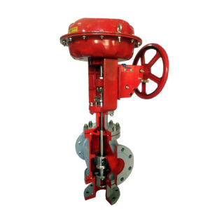
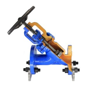
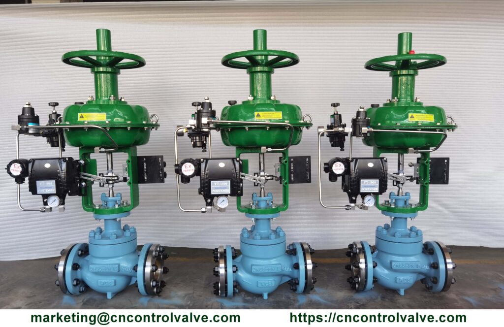
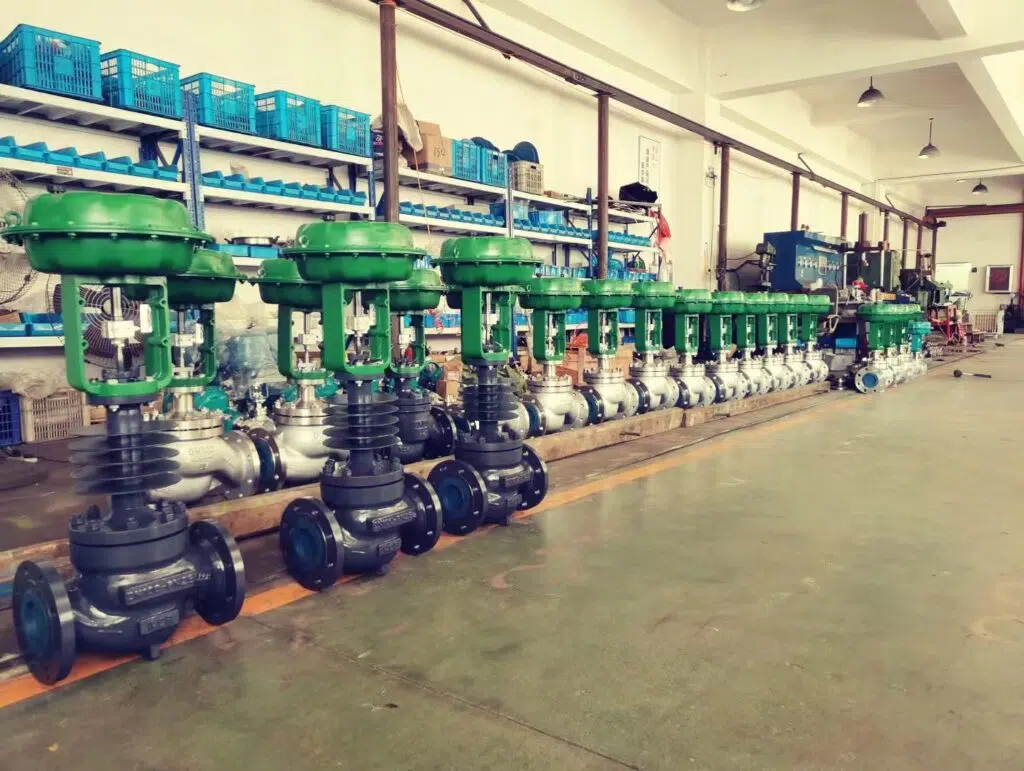
Before diving into the types of control valves, let’s explore the essential components of globe type control valves:
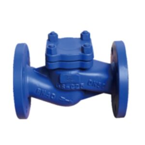
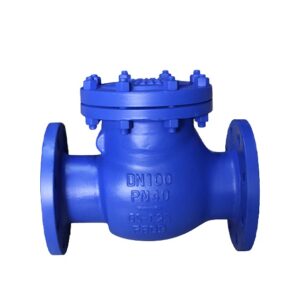
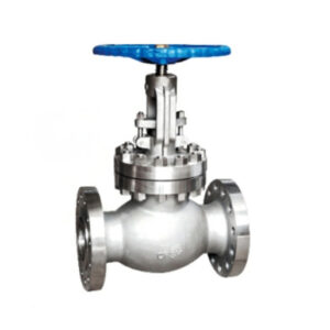
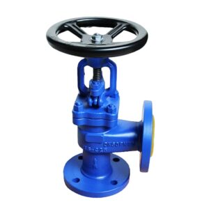
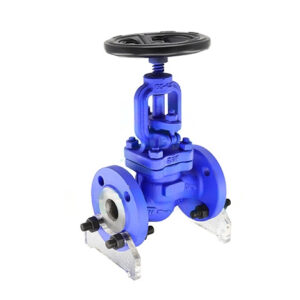
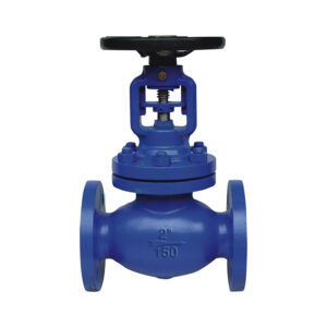
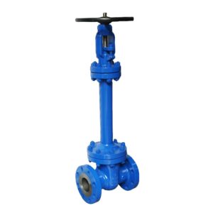
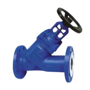
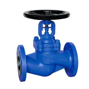
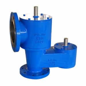
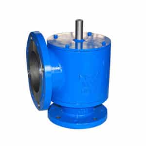
These valves regulate flow by moving a closure element in a linear motion. Common linear motion valves include:
Rotary motion valves modulate flow by rotating a closure element within the valve body. Common rotary motion valves are:
Meta Description: Dive into this comprehensive guide to understand everything about control valve applications, their functions, types, industries, and more.
Control valves play a crucial role in regulating the flow, pressure, and temperature of liquids and gases in various industries. With a wide range of applications, control valves are an essential component in many industrial processes. This article aims to cover everything you need to know about control valve applications, helping you understand their function, types, industries they serve, and much more. Whether you are a student, engineer, or a curious individual, this guide provides the knowledge you need to appreciate the significance of control valves in our modern world.
Control valves serve several critical functions in industrial processes, including:
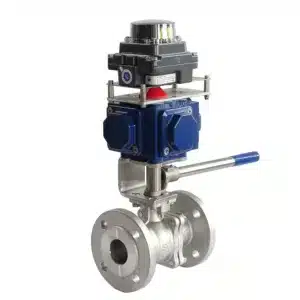
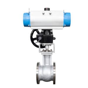
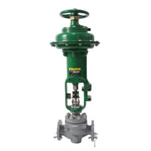
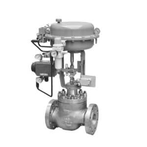
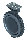
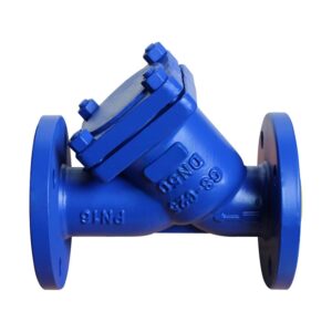
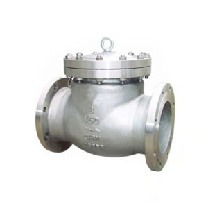
Understanding the different types of control valves is essential to their applications. Some popular control valve types include:
Control valve applications span across numerous industries, including:
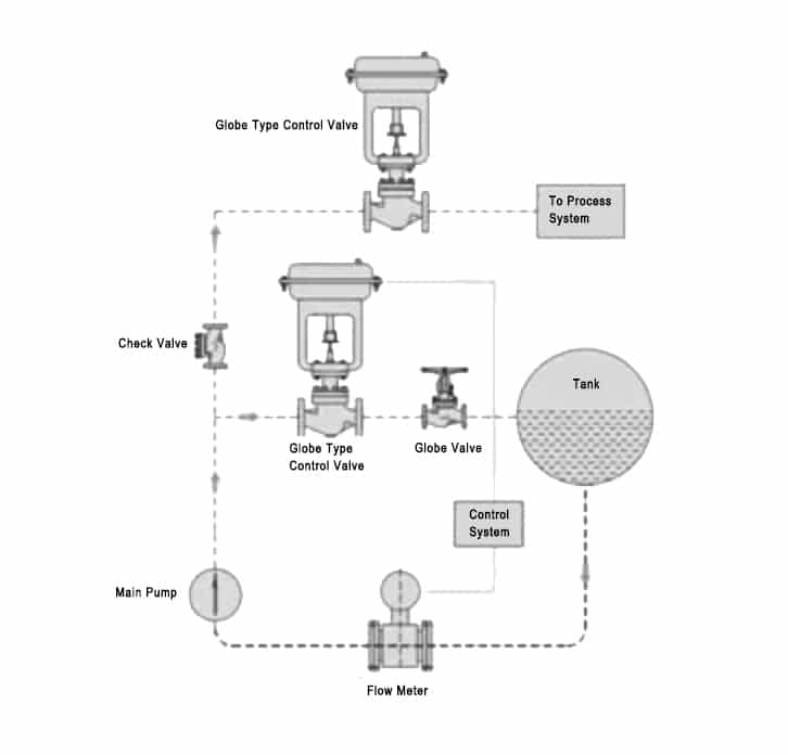
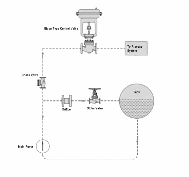
While control valves serve multiple industries, some unique applications include:
When selecting a control valve, consider the following factors:
Proper maintenance of control valves is crucial for ensuring their longevity and efficient operation. Here are some maintenance tips:
The control valve is a key element in the process control loops, the main function of a control valve is to keep some important process parameters within a required operating range, such as inlet/outlet pressure, flow rate, temperature, or level, etc.
As a final control element to modulating gas, air, steam, water, or other fluid, the control valve will compensate for the load disturbance and maintain the regulated process variable as close as possible to the desired set point.
So it is really important to learn terminology, application, technology, and all information of control valves, no matter you are an engineering, sales, end-user, or instrument expert. THINKTANK engineer department made their professional effort and rich experience in the process industry to ensure the right technical information is shared.
The following are list the general materials used for the control valve body. We will consider about 3 main factors that will affect valve materials selected for control valves. Properties, pressure, and temperature. Let’s discuss carefully one by one.
The most responsible valve manufacturers will provide the material mill test certificate for customers, which includes yield strength, hardness, and toughness data in mechanical and physical properties part.
Yield Strength is an important property of steel. It is defined as the stress at which 0.2% of the material has been permanently deformed. The higher the yield strength of the steel, the higher the resistance to permanent deformation.
Hardness is the property of resistance of a material to indentation. It is measured by the force needed to penetrate a sample of the material. Hardness can be measured using a variety of methods including Vickers hardness test, Rockwell hardness test, Brinell hardness test, and Knoop hardness test. These methods measure the hardness of materials based on their resistance to indentation. The hardness is often used to help us to estimate sliding wear resistance and resistance to erosion for control valves. It is important data if we select the right material for harsh conditions.
Toughness is the ability of a material to absorb energy and plastically deform without fracture.
Erosive wear is caused by high-velocity fluid impingement or erosive particles if flow medium.
Corrosion properties definitely is an import index for control valves, and how to select the right material resistance to corrosion from the environment or medium fluid is always the main priority for engineers.
During the harsh conditions, we apparent will face cavitation, flashing, or erosion problems for control valves. A liquid generates cavitation or flash damage for control valves often caused by upstream pressure and differential pressure. A high differential pressure affects the high velocity of flow like steam, or entrained solids which caused the potential for erosion, and the corrosion caused by the passive layer of steel is washed away from the high velocity.
Temperature is a critical matter for yield strength under the same pressure. A high temperature of medium will highly reduce the yield strength of the control valve.
If the working temperatures exceed the limit temperature of a material, a phenomenon called “creep” will be caused.
What is the creep phenomenon for valves?
A simple phenomenon to show creep deformation, we see that many ball valve seat ring PTFE has creep deformation because it exceeds the limit pressure of the material, and after the temperature is back normal, the sealing can not tight off anymore. Same as control valves, when a high temperature affects the valve body and trim material into creep phenomenon, and even after temperature and pressure are removed, the steel material still can not goes back to its original dimension.
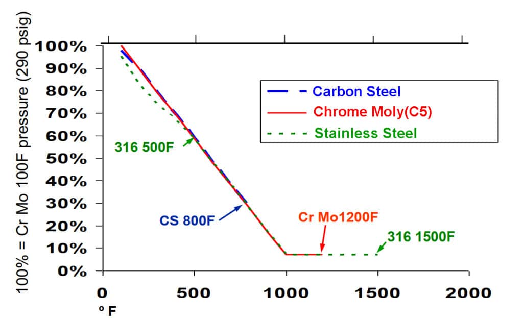
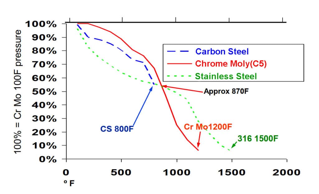
Here are the control valve material considerations for customers, engineering, or end-users reference. We should pay more attention to our existing applications, selection, and sizing based on our professional knowledge of the industry field.
| Name | Material Grade | Service Condition |
High-temperature Carbon Steel | ASTM A216 Grade WCB | Non-corrosive fluids such as water, oil, and gases at temperatures range -20°F (-30°C) and +800°F (+425°C) |
Low-temperature Carbon Steel | ASTM A352 Grade LCB | Low temperature to -50°F (-46°C). Use excluded above +650°F (+340°C). |
Low-temperature Carbon Steel | ASTM A352 Grade LC1 | Low temperature to -75°F (-59°C). Use excluded above +650°F (+340°C). |
Low-temperature Carbon Steel | ASTM A352 Grade LC2 | Low temperature to -100°F (-73°C). Use excluded above +650°F (+340°C). |
3.1/2% Nickel Steel | ASTM A352 Grade LC3 | Low temperature to -150°F (-101°C). Use excluded above +650°F (+340°C). |
1.1/4% Chrome 1/2% Moly Steel | ASTM A217 Grade WC6 | Non-corrosive fluids such as water, oil, and gases at temperatures range -20°F (-30°C) and +1100°F (+593°C). |
2.1/4% Chrome | ASTM A217 Grade C9 | Non-corrosive fluids such as water, oil, and gases at temperatures range -20°F (-30°C) and +1100°F (+593°C). |
5% Chrome 1/2% Moly | ASTM A217 Grade C5 | Mild corrosive or erosive applications and non-corrosive applications at temperatures between -20°F (-30°C) and +1200°F (+649°C). |
9%Chrome 1% Moly | ASTM A217 Grade C12 | Mild corrosive or erosive applications and non-corrosive applications at temperatures between -20°F (-30°C) and +1200°F (+649°C). |
12% Chrome Steel | ASTM A487 Grade CA6NM | Corrosive application at temperatures between -20°F (-30°C) and +900°F (+482°C). |
12% Chrome | ASTM A217 Grade CA15 | Corrosive application at temperatures up to +1300°F (+704°C) |
Stainless steel 316 | ASTM A351 Grade CF8M | Corrosive or either extremely low or high-temperature non-corrosive services between -450°F (-268°C) and +1200°F (+649°C). Above +800°F (+425°C) specify carbon content of 0.04% or greater. |
Stainless steel 347 | ASTM 351 Grade CF8C | Mainly for high temperature, corrosive applications between -450°F (-268°C) and +1200°F (+649°C). Above +1000°F (+540°C) specify carbon content of 0.04% or greater. |
Stainless steel 304 | ASTM A351 Grade CF8 | Corrosive or extremely high temperatures non-corrosive services between -450°F (-268°C) and +1200°F (+649°C). Above +800°F (+425°C) specify carbon content of 0.04% or greater. |
Stainless steel 304L | ASTM A351 Grade CF3 | Corrosive or non-corrosive services to +800F (+425°C). |
Stainless steel 316L | ASTM A351 Grade CF3M | Corrosive or non-corrosive services to +800F (+425°C). |
Alloy-20 | ASTM A351 Grade CN7M | Good resistance to hot sulfuric acid to +800F (+425°C). |
Monel | ASTM 743 Grade M3-35-1 | Weldable grade. Good resistance to corrosion by all common organic acids and saltwater. Also highly resistant to most alkaline solutions to +750°F (+400°C). |
Hastelloy B | ASTM A743 Grade N-12M | Well suited for handling hydrofluoric acid at all concentrations and temperatures. Good resistance to sulphuric and phosphoric acids to +1200°F (+649°C). |
Hastelloy C | ASTM A743 Grade CW-12M | Good resistance to span oxidation conditions. Good properties at high temperatures. Good resistance to sulphuric and phosphoric acids to +1200°F (+649°C). |
Inconel | ASTM A743 Grade CY-40 | Very good for high-temperature service. Good resistance to spangly corrosive media and atmosphere to +800°F (+425°C). |
Bronze | ASTM B62 | Water, oil, or gas: up to 400°F. Excellent for brine and seawater service. |
The corrosion resistance, hardness, and toughness of the material are improved by adding alloying elements to the base steel.
The principal harder in steel is carbon. The more carbon that is added (up to 1.2%), the harder it gets.
Molybdenum adds strength to steel and increases corrosion resistance to chlorides.
Chromium is the element in steel to against corrosion and increases heat resistance.
Nickel improves corrosion resistance and toughness and is used to increase the corrosion resistance of austenitic stainless steel.
Silicon is the principal deoxidizer used in steel making. It also increases strength and hardness for steel.
Manganese contributes to strength and hardness.
Sometimes added sulfur element is in controlled amounts for easier machining and welding.
Added Vanadium increases toughness and fatigue resistance.
Here is the standard of control valve seat leakage refers to standard ANSI/FCI 70-2-2006 superseding ANSI B16.104.
| Leakage Class Designation | Maximum Leakage Allowable | Test Medium | Test Pressure | Testing Procedures Required for Establishing Rating |
| CLASS I | – | – | – | No test required provided user and supplier so agree |
| CLASS II | 0.5% of rated capacity | Air or water at 50-125 F (10-52C) | 45-60 psig or max. operating differential whichever is lower | Pressure applied to valve inlet with outlet open to atmosphere or connected to a low head loss measuring device full normal closing thrust provided by actuator. |
| CLASS III | 0.1% of rated capacity | Air or water at 50-125 F (10-52C) | 45-60 psig or max. operating differential whichever is lower | Pressure applied to valve inlet with outlet open to atmosphere or connected to a low head loss measuring device full normal closing thrust provided by actuator. |
| CLASS IV | 0.01% of rated capacity | Air or water at 50-125 F (10-52C) | 45-60 psig or max. operating differential whichever is lower | Pressure applied to valve inlet with outlet open to atmosphere or connected to a low head loss measuring device full normal closing thrust provided by actuator. |
| CLASS V | 0.0005 ml per minute of water per inch of port diameter per psi differential | Water at 50-125F (10-52C) | Max service pressure drop across valve plug, not to exceed ANSI body rating. | Pressure applied to valve inlet after filling entire body cavity and connected piping with water and stroking valve plug closed. Use net specified max actuator thrust, but no more, even if available during test. Allow time for leakage flow to stabilize. |
| CLASS VI | Not to exceed amounts shown in the following table based on port diameter. | Air or nitrogen at 50-125 F (10-52C) | 50 psig or max rated differential pressure across valve plug whichever is lower. | Actuator should be adjusted to operating conditions specified with full normal closing thrust applied to valve plug seat. Allow time for leakage flow to stabilize and use suitable measuring device. |
| NOMINAL PORT DIAMETER (INCHES) | NOMINAL PORT DIAMETER (MILLIMETERS) | LEAK RATE (ML PER MINUTE) | LEAK RATE (BUBBLES / MINUTE*) |
| 3 | 76 | 0.9 | 6 |
| 4 | 102 | 1.7 | 11 |
| 6 | 152 | 4 | 27 |
| 8 | 203 | 6.75 | 45 |
| 10 | 254 | 9 | 63 |
| 12 | 305 | 11.5 | 81 |
Generally, we will consider selecting the suitable material for the control valve body and trim from 4 factors.
Here we will list the typical materials for globe type, butterfly type, ball type of control valve.
| Valve Type | Material Type | Body Material | Trim Material | Stem Material | Seat Material |
| Ball Type | Carbon Steel | ASTM A352 gr. LCC, A216 WCB, A216 WCC | 316 SS | 316 SS | 316 SS |
| Stainless Steel | 316 SS | 316 SS | 316 SS | 316 SS | |
| Incoloy or Inconel | UNS N08825 or A350 LF2, A216 WCB with UNS N06625 Overlay | UNS N06625 | UNS N07718 | UNS N06625 | |
| Bronze | BRONZE (UNS C95800) | BRONZE (UNS C95800) | BRONZE (UNS C95800) | BRONZE (UNS C95800) | |
| Duplex & Super Duplex | ASTM A890 GR. 4A (UNS J92205) (Duplex~22% Cr), ASTM A182 GR. F53 (UNS S32750) or F55 (UNS S32760) (Super Duplex~25% Cr) | ASTM A182 F51, F53, F55 | ASTM A276 UNS S31803, S32750, S32760 | ASTM A182 F51, F53, F55 | |
| 6 Moly SS | UNS S31254 (6 Moly Stainless Steel) | UNS S31254 | UNS S31254 | UNS S31254 | |
| Butterfly Type | – | Cast Iron, Carbon Steel, Stainless Steel, Hastelloy, Brass, Nickel Alloys Steel, Titanium Alloys, Nickel Aluminum Bronze, Duplex Steel | Cast Iron, Carbon Steel, Stainless Steel, Hastelloy, Brass, Nickel Alloys Steel, Titanium Alloys, Nickel Aluminum Bronze, Duplex Steel | Stainless Steel, Inconel, Monel | Soft Seat: PTFE, RTFE, EPDM, Buna-N, Viton, Neoprene Metal Seat: Inconel, Stainless Steel |
| Globe Type | – | Carbon Steel, Stainless Steel, Hastelloy, Brass, Nickel Alloys Steel, Titanium Alloys, Nickel Aluminum Bronze, Duplex Steel | 316SS, 416SS, 17-4PH | Stainless Steel, Inconel, Monel | Soft Seat: PTFE, RTFE, Viton Metal Seat: Inconel, Stainless Steel |
Should you have any questions or requirements about control valves, self-operated pressure regulators, high-performance butterfly valves, or other industrial valves, please feel free to contact us for further communication.
The order is just the beginning of the service. We treat every customer seriously and sincerely, try our best to meet the customer’s customized requirements, and provide customers with cost-effective valves as much as possible. Maintaining the interests of our customers is the foundation of our development.
Avoid your inquiry is delay response, please enter your WhatsApp/Wechat/Skype along with the message, so we can contact you at the very first time.
We will reply you within 24 hours. If for urgent case, please add WhatsApp: +86 185 1656 9221, or WeChat: +86 199 2125 0077. or call +86 189 5813 8289 directly.

We will reply you within 24 hours. If for urgent case, please add WhatsApp: +86 199 2125 0077, or WeChat: +86 199 2125 0077. Or call +86 189 5813 8289 directly.


Just leave your name, email, and simple message or requirements, We will contact you within 1 hour.
WhatsApp: +86 199 2125 0077
Skype ID: sowell85
Wechat ID: +86 199 2125 0077