


A pneumatic on/off valve is used for tight closing applications for liquids, gases, and vapors. It has standard options such as temperature extensions and metal bellows seals.
As this control valve is designed according to the modular assembly principle, so it can be assembled with a pneumatic actuator and an option with a handwheel, it also can be equipped with other accessories, such as limit switches, solenoid valve, and so on.

Modulating type control valves include single-seated control valves, double-seated control valves, angle type control valves, cage guided control valves, and so on.
For example, cage guided type balanced trim, movement balanced ring, fission labyrinth type standard cage, optional movement seal ring, high strength structure. The 510D series is the most pointed control valve in the high differential pressure operating mode, has used the labyrinth type valve cage, has the characteristic which multistage falls pressure, the multilayered labyrinth gasket type valve can reduce the fluid noise and eliminate cavitation as well as the multi-hole cage valve. Moreover, reduces the volume greatly, the trim in the valve is interchangeable between the HCB series control valve with the HSC series Cage Guided control valve.

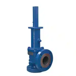
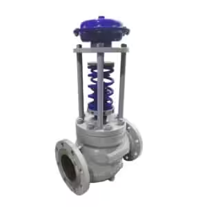
A self-acting control valve is also known as a self-operated pressure regulator, which doesn’t need any auxiliary power to drive the valve, the self-acting control valve through the medium energy to operate the valve itself, that’s why it is called self-acting or self-operated. A self-operated control valve can realize the adjustment of temperature, pressure, differential pressure, flow rate, and other parameters. It has the characteristics of simple structure, low price, reliable action, and so on. It is suitable for occasions where flow rate changes are small, adjustment accuracy is not high, or instrument air/power supply is difficult.


Manual Control Valves are valves that are operated by manual input, typically by turning a handwheel, lever, or crank. The operator manually adjusts the position of the valve to control the flow of a fluid through a system. This control valve is still globe type, and they are used for both throttling and shut-off. A disc or plug inside the valve can be moved closer to or further away from the valve seat to adjust flow.

Electric/Motorized Control Valves, also known as Electric Actuated Control Valves, are valves that can be controlled remotely or automatically by an electric actuator. The actuator uses an electric motor to control the valve’s position, which in turn controls the flow of fluid through the valve.
These types of valves are commonly used in various industrial applications where precise control of fluid flow is needed. They can be found in water treatment plants, oil and gas pipelines, chemical processing facilities, HVAC systems, and many other settings.
The operation of an Electric/Motorized Control Valve can be modulating or on/off:
Modulating control: In this mode, the valve can be adjusted to any position between fully open and fully closed to control the flow rate of the fluid. This is useful in applications where flow rates need to be adjusted dynamically based on changing process conditions.
On/Off control: In this mode, the valve is either fully open or fully closed. This is useful in applications where flow needs to be completely stopped or allowed to flow freely, such as in safety shut-off applications.
The electric actuator typically receives a signal from a control system, such as a PLC (Programmable Logic Controller) or DCS (Distributed Control System), which tells it what position to move the valve to. This allows for precise, automatic control of fluid flow rates based on the needs of the process.
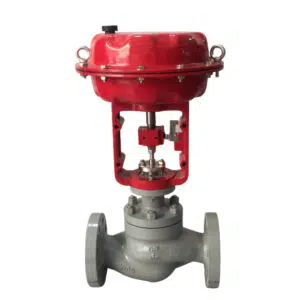
Pneumatic or Cylinder Control Valves are control valves that use a pneumatic actuator for operation. The actuator uses air pressure to control the position of the valve, which in turn controls the flow of fluid through the valve.
In a typical pneumatic actuator, air pressure is applied to a diaphragm or a piston, which then moves a stem attached to the valve. The stem movement can either open or close the valve, or move it to any position in between for modulating control.
Pneumatic control valves can be “normally open”, which means they stay open when no air pressure is applied, or “normally closed”, meaning they stay closed when no air pressure is applied. They can also be double-acting, meaning that air pressure can be used to both open and close the valve.
These valves are widely used in various industries such as oil and gas, water and wastewater, power generation, and chemical processing. Pneumatic control valves are popular because of their reliability, low maintenance, and because they can be easily integrated into control systems.
Pneumatic actuators also have the advantage of being safe to operate in explosive environments, as they do not create sparks like some electrical devices can. They also can deliver a high amount of force, which can be useful for operating larger valves.
In this type, the flow of the fluid is modified by the closure member in rotary motion. Rotary motion valves are of three types.
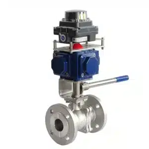
As the name suggests, the shape of the valve is like a ball with a container for fluid flow. Right at the opening, this valve enables the flow and after being rotating at 90° it stops the flow. Ball valve has good resistance towards high temperature & high pressure. The advantage of the ball valve is easy to maintain and has low torque. On the other hand, it also has the disadvantage of causing corrosion when the fluid gets trapped inside the valve mainly during a closed position.
Butterfly valve has a disc rotating at 90˚ inside the pipe. The disc allows the stem to pass through it and is supported by both ends. Similar to the ball valve, the butterfly valve also stops with a right-angle rotation. The butterfly valve has the capacity of controlling large flow and low-pressure applications. It is affordable and has a quick opening. It has only one disadvantage of loose shut-off.

The plug valve is available in both cylindrical and tapered shapes. At the time of opening of this valve, both inlet and outlet ends of this valve, are connected to give a flow line. This valve is suitable for both chemical and petrochemical industries. The plug valve has advantages like less maintenance, fewer requirements of headroom, and quick opens. It has a low-pressure drop and doesn’t provide loose shut-off like a butterfly valve. The plug valve also has disadvantages like not affordable and is not useful for throttling action.


Steam control valves with pneumatic actuators are widely used for industrial processes, such as sugar mills, power plants, chemical industry, oil, and gas.
Usually, it is assembly with E/P or P/P valve positioner to receive an input signal from the controller room, 4-20mA or 3-15psi.

Steam control valves with pneumatic actuators are designed to regulate the flow of steam in various industrial applications. They use pneumatic actuators to control the opening and closing of the valve.
Here’s how they work:
Pneumatic Actuator: The pneumatic actuator uses air pressure to create motion that opens or closes the valve. It typically operates via a diaphragm or a piston mechanism. When pressurized air is introduced, it moves the diaphragm or piston, which in turn moves the valve stem and changes the position of the valve. These actuators can be spring return (single acting – where air pressure opens or closes the valve and a spring returns the valve to its original state when the air pressure is released) or double acting (where air pressure can both open and close the valve).
Steam Control Valve: The valve component of this system is specifically designed to handle the high temperature and pressure of steam. It might be a globe, gate, or ball valve, depending on the specific needs of the system. When the valve is opened or closed by the actuator, it allows more or less steam to pass through, effectively controlling the flow rate of steam in the system.
These valves are used in a variety of industries and applications, including power plants (where steam is used to generate electricity), food processing facilities, and any other application where the flow of steam needs to be precisely controlled.
In a system with these valves, the pneumatic actuator typically receives signals from a control system, which tells it how far to open or close the valve. This allows for automatic and precise control of steam flow based on the current requirements of the system.
Description
The multi-spring membrane pneumatic actuators of P/R type are applied for control operation of control valves and other positioning elements in automatic industrial systems. There are two following design options of the actuator:
– Direct action (air – advances the stem)
– Reverse action (air – retracts the stem)
Features

1. Up diaphragm castings 2. Diaphragm
3. Diaphragm plate 4. Spring
5. Down diaphragm castings 6. Actuator stem
7. Yoke 8. Adjust nut 9. Travel indicator

1. Up diaphragm castings 2. Diaphragm
3. Diaphragm plate 4. Spring
5. Down diaphragm castings 6. Actuator stem
7. Yoke 8. Adjust nut 9. Travel indicator
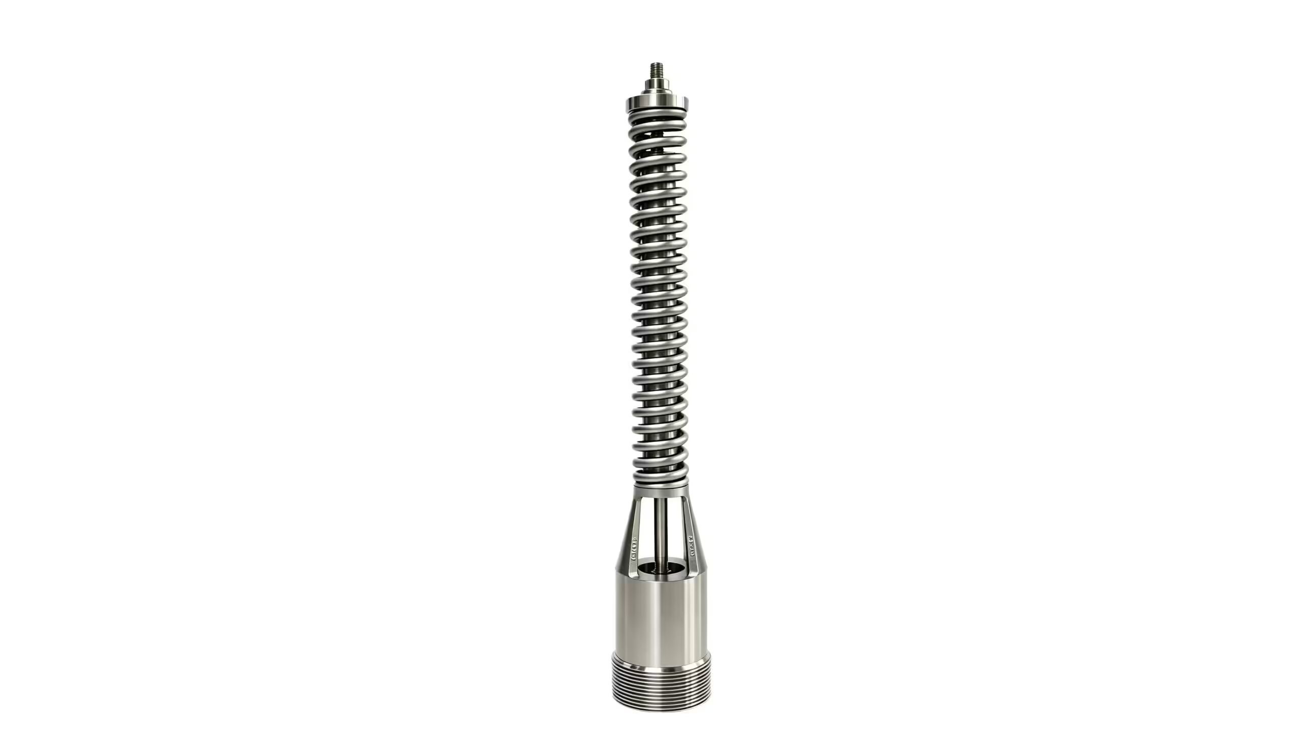
Model TT-667 actuator is a reverse-acting, spring-opposed diaphragm actuator. The actuator positions the valve plug in response to varying pneumatic loading pressure on the actuator diaphragm.
Description
Our Model TT-667 diaphragm actuator with a single spring is 100% to replace Fisher 667 actuators, which are designed to ensure stable on/off or throttling operation of the control valve. These spring-balanced membrane actuators respond to the pneumatic output signal of the controller or valve positioner to determine the position of the valve plug. 667 diaphragm actuator is a reverse-acting.
Specifications:

It could be a single-seated, double-seated, cage-guided, top-guided globe type trim design for the industrial engineering process. The control valve body assembly with a pneumatic actuator to modulate or shut off downstream pressure, flow rate, or temperature.

Three ways control valves are service for diverting or mixing service. The pneumatic actuator is designed as a rubber diaphragm with multi-springs, or piston/cylinder type pneumatic actuator with single-acting or double-acting.

Three-way globe type control valves are specialized control valves that have three ports and two valve seats, which allow the valve to connect two ports together at a time in different combinations. This allows them to perform several functions that would otherwise require multiple two-way valves.
Here’s a general idea of how they work:
Mixing Application: In the ‘mixing’ configuration, fluid can enter the valve from two different ports and then mix together and exit through the third port. This configuration is often used in heating and cooling systems where there is a need to mix hot and cold fluids to achieve a specific temperature output.
Diverting Application: In the ‘diverting’ configuration, fluid enters the valve from one port and can be directed to either of the other two ports. This is often used where a fluid needs to be directed towards two different paths in a system.
Three-way globe type control valves are typically actuated (opened and closed) using a manual wheel, an electric motor, a pneumatic or hydraulic cylinder, or a solenoid. The actuator can adjust the position of the internal mechanism (typically a disc or a ball) to change the path of the fluid through the valve, allowing for precise control over the fluid flow.
Like all globe valves, three-way globe type control valves have good throttling abilities, which means they can adjust the flow rate of the fluid very precisely. This makes them ideal for applications where precise control over fluid flow is important. However, they also have a higher pressure drop than other types of valves due to the more complex flow path, which can be a consideration in system design.
Control Valve Failure Position 101