
Safety valves are automatic valves that release substances (like gas, steam, or liquid) from a boiler, pressure vessel, or other system when the pressure or temperature exceeds preset limits. They are engineered to open at a specific pressure and temperature to ensure safety and prevent potential accidents or equipment failure.
The primary role of a safety valve is to maintain pressure within safe limits to prevent equipment damage or catastrophic failures.
They are vital for the safety of the operating personnel and to prevent potential hazards associated with overpressure.
Safety valves are mandated in many industries by regulatory bodies to ensure safe and reliable operation of pressure systems.
Conventional safety valves are defined in various standards, and a common characteristic among them is that their operational features are influenced by backpressure in the discharge system. It is important to acknowledge that the total backpressure comprises two components: superimposed backpressure and built-up backpressure.
Superimposed backpressure refers to the static pressure present on the outlet side when a valve is closed. On the other hand, built-up backpressure represents the additional pressure generated on the outlet side during valve discharge. In the case of a conventional safety valve, only the superimposed backpressure impacts the opening characteristics and set value. However, the combined backpressure modifies the blowdown characteristics and re-seat value.
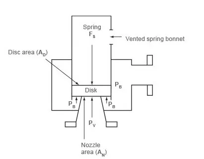
According to the ASME/ANSI standard, conventional valves are further classified by having a spring housing that is vented to the discharge side of the valve. If the spring housing is vented to the atmosphere instead, any superimposed backpressure will still affect the operational features. This distinction can be observed in Figure 9.2.1, which depicts schematic diagrams of valves with spring housings vented to the discharge side of the valve and the atmosphere.
A wide variety of safety valves are available to meet the diverse requirements and performance criteria of different industries. Moreover, national standards establish several distinct types of safety valves.
The ASME I standard and the ASME VIII standard pertain to applications involving boilers and pressure vessels, while the ASME/ANSI PTC 25.3 standard pertains to safety valves and relief valves. These standards not only outline the performance characteristics but also define the various types of safety valves employed.
An ASME I valve is a safety relief valve that complies with the specifications outlined in Section I of the ASME pressure vessel code for boiler applications. This valve is designed to open when the pressure exceeds 3% of the predetermined level and close when it falls within 4%. Typically, it includes two blowdown rings and can be identified by the presence of a ‘V’ stamp issued by the National Board.
On the other hand, an ASME VIII valve is a safety relief valve that conforms to the requirements specified in Section VIII of the ASME pressure vessel code for pressure vessel applications. This valve opens when the pressure exceeds 10% of the predetermined level and closes when it falls within 7%. It is identifiable by the presence of a ‘UV’ stamp issued by the National Board.
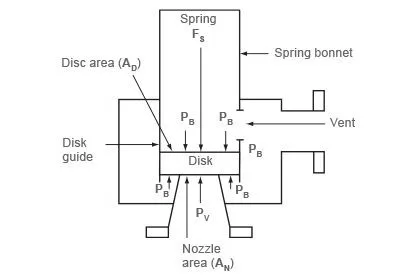
When considering the forces acting on the disc, specifically the area AD, it becomes evident that the necessary force to initiate the opening (which is equal to the product of inlet pressure PV and the nozzle area AN) is a combination of the spring force FS and the force resulting from the backpressure PB on the top and bottom of the disc. If we examine the scenario where a spring housing is ventilated to the discharge side of the valve of the ASME conventional safety relief valve), the formula for the required opening force can be expressed as follows:
PV x AN = FS + PB x AD – PB (AD – AN)
This can then be simplified to Equation
Where:
PV = Fluid inlet pressure
AN = Nozzle area
FS = Spring force
PB= Back pressure
Consequently, the application of additional backpressure results in an augmentation of the closing force, and an increased inlet pressure is necessary to raise the disc.
For a valve equipped with a spring housing vented to the atmosphere, the force required for opening is as follows:
Where:
Pv = Fluid inlet pressure
An = Nozzle area
Fs = Spring force
PB = Backpressure
AD = Disc area
Consequently, the superimposed backpressure, in conjunction with the vessel pressure, counteracts the spring force, resulting in a lower-than-anticipated opening pressure.
In both scenarios, it is essential to account for the impact of significant superimposed backpressure when devising a safety valve system.
Moreover, it is crucial to consider the effects of accumulated backpressure as the valve initiates its opening process. In the case of a conventional safety valve where the spring housing is vented to the discharge side of the valve, the influence of accumulated backpressure can be assessed by referring to Equation A and acknowledging that, once the valve begins to open, the inlet pressure combines the set pressure (PS) and the overpressure (PO).
The equation (PS + PO) x AN = FS + PB x AN, which simplifies to Equation
Where:
PS= Set pressure of safety valve
AN = Nozzle area
FS = Spring force
PB = Back pressure
PO = Overpressure
Therefore, the superimposed backpressure interacts with the vessel pressure to counteract the spring force, resulting in a lower than anticipated opening pressure.
In either scenario, when designing a safety valve system, it is essential to account for the impact of significant superimposed backpressure on the set pressure.
Furthermore, when the valve initiates its opening process, the repercussions of accumulated backpressure must also be taken into consideration. In the case of a conventional safety valve with the spring housing vented to the discharge side of the valve, the effect of built-up backpressure can be determined by applying Equation A and recognizing that the inlet pressure, once the valve begins to open, comprises both the set pressure (PS) and the overpressure (PO).
The simplified expression for this relationship is as follows: (PS + PO) x AN = FS + PB x AN, as shown in Equation C.
Balanced safety valves encompass mechanisms that nullify the impact of backpressure. Two fundamental designs can be employed to accomplish this.
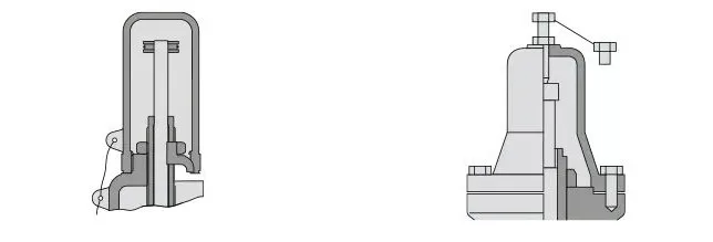
The piston valve exhibits several variations, but generally comprises a disc in the form of a piston. The movement of this disc is confined by a vented guide. The areas of the piston’s top face (AP) and the nozzle seat (AN) are intentionally designed to be equivalent. This design ensures that both the upper and lower surfaces of the disc, exposed to backpressure, possess equal effective areas, thereby achieving balance in opposing forces. The following figure shows the vented spring bonnet, enabling the top face of the piston to be exposed to atmospheric pressure.
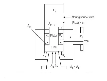
Upon examination of the forces applied to the piston, it becomes clear that this particular valve is no longer influenced by any opposing pressure.
Where:
PV = Fluid inlet pressure
AN = Nozzle area
FS = Spring force
PB = Backpressure
AD = Disc area
AP = Piston area
Since AP equals AN, the last two terms of the equation are equal in magnitude and cancel out of the equation. Therefore, this simplifies to Equation
where:
PV = Fluid inlet pressure
AN = Nozzle area
FS= Spring force
A bellows type balanced safety valve is a valve that uses a bellows mechanism to balance the forces acting on the valve disc. The bellows is attached to the upper surface of the disc and the spindle guide, and it prevents backpressure from affecting the valve opening pressure.
The bellows allows air to flow freely in and out as it expands or contracts. However, bellows failure can impact the valve’s set pressure and capacity, so there should be a mechanism in place to detect any unusual fluid flow through the bellows vents. Some bellows balanced safety valves also have an auxiliary piston to counter the effects of backpressure in case of bellows failure. These valves are typically used in critical applications in the oil and petrochemical industries.
The bellows not only reduces the impact of backpressure but also isolates the spindle guide and the spring from corrosive process fluids.
However, bellows type balanced safety valves are more expensive than unbalanced ones. They are usually employed when high pressure manifolds are unavoidable or in critical applications that require precise set pressure or blowdown.
This particular safety valve utilizes the flowing medium itself, through a pilot valve, to exert the necessary closing force on the safety valve disc. The pilot valve, in essence, functions as a miniature safety valve.
Two primary variations of pilot operated safety valves exist, specifically the diaphragm type and the piston type.
The diaphragm type is typically suitable for low pressure applications and exhibits a proportional action, commonly observed in relief valves employed in liquid systems. As a consequence, its usefulness is minimal in steam systems, and thus, it will not be further discussed within this document.
In contrast, the piston type valve incorporates a primary valve equipped with a piston-shaped closing mechanism (or obturator), as well as an external pilot valve. A diagram of a typical piston-type, pilot operated safety valve is presented in the following figure.
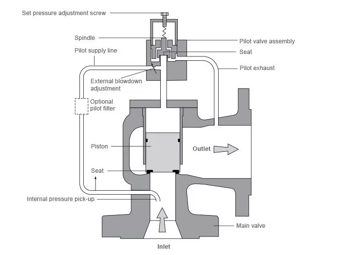
The main valve incorporates a piston and seating arrangement designed in such a way that the bottom area of the piston, exposed to the inlet fluid, is smaller than the top area. This configuration ensures that, despite both ends of the piston being subjected to the fluid at equal pressures, the larger top area generates a greater closing force compared to the inlet force. Consequently, the resulting downward force firmly secures the piston onto its seat.
In situations where the inlet pressure increases, the closing force on the piston also rises, thereby maintaining a consistently tight shut-off. However, once the inlet pressure reaches the predetermined set pressure, the pilot valve pops open to release the fluid pressure above the piston. Due to the reduced fluid pressure acting on the upper surface of the piston, the inlet pressure creates an upward force causing the piston to disengage from its seat. As a result, the main valve also opens, allowing for the discharge of the process fluid.
Upon sufficiently lowering the inlet pressure, the pilot valve recloses, preventing further fluid release from the top of the piston. This action reestablishes the net downward force, causing the piston to reseat.
Pilot operated safety valves exhibit excellent overpressure and blowdown performance, with potential blowdown as low as 2%. Their use is particularly advantageous when a narrow margin is required between the set pressure and the operating pressure of a system. Furthermore, pilot operated valves are available in larger sizes, making them the preferred choice for safety valves handling larger capacities.
However, it is important to note that pilot connecting pipes, with their small bore, can be susceptible to blockage from foreign matter or condensate buildup. Consequently, such blockages can lead to valve failure, either in the open or closed position, depending on the location of the blockage.
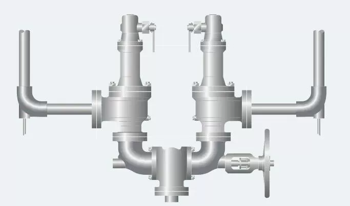
Change-over safety valves enable the installation of two valves alongside one another, with one actively operating while the other is isolated. This advantageous arrangement allows for uninterrupted service during routine maintenance or vessel protection. It is noteworthy that the design of changeover valves ensures the unobstructed flow area when they are engaged.
Additionally, changeover valves find utility in connecting safety valve outlets, eliminating the necessity for duplicating the discharge pipework. To ensure safety, the operation of both the inlet and outlet changeover valves must be controlled and synchronized. Typically, this is achieved through a chain drive system that interconnects the handwheels of both valves.
When determining the safety valve’s inlet pressure drop, careful consideration should be given to the pressure loss induced by the changeover valve. It is advised to limit this pressure drop to 3% of the preset pressure.
The terms “full lift,” “high lift,” and “low lift” pertain to the extent of movement exhibited by the disc as it transitions from its closed state to the position required for achieving the certified discharge capacity. This movement has a direct impact on the discharge capacity of the valve.
A full lift safety valve encompasses sufficient disc lift to eliminate the influence of the curtain area on the discharge area. Consequently, the valve’s capacity is determined by the bore area, which occurs when the disc elevates at least one-quarter of the bore diameter. In general steam applications, a full lift conventional safety valve often proves to be the most suitable choice.
In a high lift safety valve, the disc ascends a minimum distance equivalent to one-twelfth of the bore diameter. As a result, the discharge area is determined by the curtain area and, in turn, the position of the disc. High lift valves typically exhibit significantly lower discharge capacities compared to full lift valves. Opting for a full lift valve, with a nominal size several times smaller than that of a corresponding high lift valve, can often yield cost advantages. Additionally, high lift valves are commonly employed with compressible fluids for their more proportional action.
Low lift valves witness the disc elevating only by a distance equivalent to one-twenty-fourth of the bore diameter. Here, the discharge area is solely determined by the disc’s position, with minimal lift leading to significantly lower capacities when compared to full or high lift valves.
A low-lift safety valve is a type of valve where the discharge area is determined by the position of the disc. On the other hand, a full lift safety valve does not rely on the position of the disc to determine the discharge area.
A full bore safety valve is designed without protrusions in the bore, allowing the valve to lift sufficiently so that the minimum area at any section, including at or below the seat, becomes the controlling orifice.
In a conventional safety relief valve, the spring housing is vented to the discharge side. This means that changes in the backpressure directly affect the valve’s operational characteristics.
A balanced safety relief valve is designed to minimize the impact of backpressure on the operational characteristics of the valve.
A pilot operated pressure relief valve combines the major relieving device with a self-actuated auxiliary pressure relief device, which controls its operation.
A power-actuated safety relief valve combines the major pressure relieving device with a device that requires an external source of energy to control it.
Standard safety valve refers to a valve that, upon opening, attains the necessary lift degree for discharging the mass flowrate within a pressure rise not exceeding 10%. This type of valve operates with a pop action and is occasionally referred to as “high lift.”
Full lift safety valve, also known as Vollhub safety valve, rapidly opens within a 5% pressure rise after the commencement of lift until it reaches the complete lift as defined by its design. The proportional range prior to rapid opening should not exceed 20%.
Direct loaded safety valve functions with an opening force beneath the valve disc, countered by a closing force such as a spring or weight.
Proportional safety valve is distinguished by its steady opening relative to increasing pressure. It does not experience sudden opening within a 10% lift range without an accompanying pressure increase. These safety valves achieve the necessary lift for mass flow discharge within a pressure not exceeding 10% after opening.
Diaphragm safety valve is a direct loaded safety valve wherein the linear moving and rotating elements, as well as springs, are shielded from the fluid’s effects by a diaphragm.
Bellows safety valve is a direct loaded safety valve that provides protection to sliding and partially or fully rotating elements, as well as springs, from the fluid’s impacts through the use of a bellows. The bellows may be designed to compensate for backpressure influences.
Controlled safety valve comprises a main valve and a control device. This category also encompasses direct acting safety valves with supplementary loading, where an additional force increases the closing force until the set pressure is reached.
This type of safety valve opposes the loading caused by the fluid pressure beneath the valve disc using only a direct mechanical loading device, such as a weight, lever and weight, or a spring.
An assisted safety valve incorporates a powered assistance mechanism that allows the valve to be lifted at a pressure lower than the set pressure. Even in the event of a failure of the assistance mechanism, it still satisfies all the requirements outlined for safety valves in the standard.
Until the pressure at the inlet of the safety valve reaches the set pressure, this safety valve possesses an additional force that enhances the sealing force.
A pilot-operated safety valve is a type of safety valve that functions through the operation and regulation of fluid discharge from a pilot valve. The pilot valve, in turn, is a direct loaded safety valve that adheres to the stipulations outlined in the standard.
| Body Material | Condition |
| Bronze | Frequently employed in the fabrication of small screwed valves intended for general duty across steam, air, and hot water systems with a maximum pressure rating of 15 bar. |
| Cast iron | It is extensively utilized in ASME type valves, although its application is typically restricted to a pressure limit of 17 bar. |
| Cast steel | Often selected for higher pressure valves, is suitable for systems operating at pressures up to 40 bar. |
| Stainless Steel | Stainless steel is used for corrosive or clean steam duty. |
| Austenitic stainless steel | Austenitic stainless steel finds its utility in specialized applications such as those involving food, pharmaceuticals, or clean steam. |
| Seal Material | Condition |
| EPDM | Water |
| Viton | High-temperature gas condition |
| Nitrile | Air and oil condition |
| Stainless Steel | Standard material, best for steam |
| Satellite | Wear resistant for tough condition |
ASME VIII is part of the American Society of Mechanical Engineers (ASME) Boiler and Pressure Vessel Code, and provides detailed guidelines for the design, construction, and operation of safety valves in pressure vessels. These standards are critical for ensuring the safety and reliability of equipment used in industrial applications.
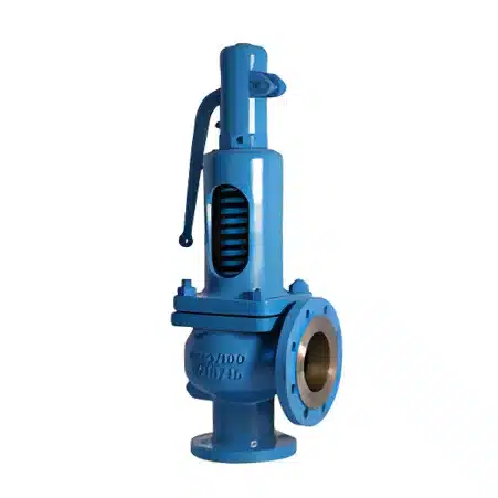
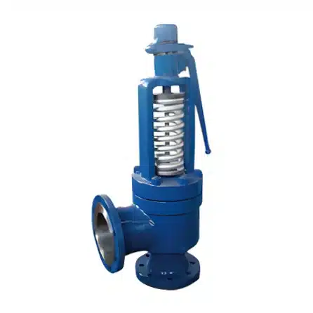
The 5210 series includes a regular spring-type safety valve, while the 5210B type is a back-pressure balanced bellows spring-type safety valve. They are designed, manufactured, and inspected according to API526 and API527 standards. These valves are suitable for air, gas, water vapor, liquid, and other media.
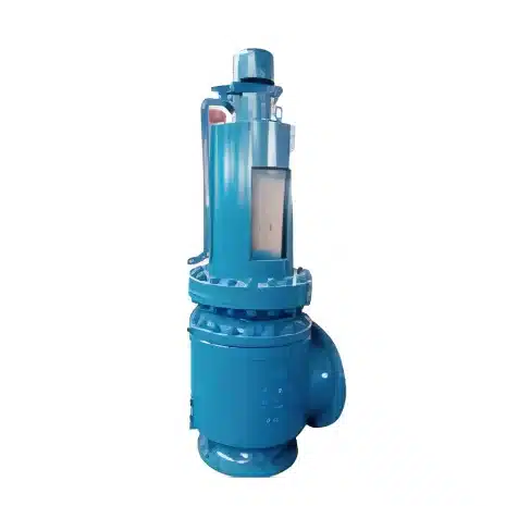
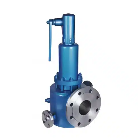
The 5211 series conventional spring-type safety valve, 5211B is a back-pressure balanced bellows spring-type safety valve. This is a large-diameter safety valve which developed on the basis of API526 standard. Applicable to air, gas, water vapor, liquid, and other media.
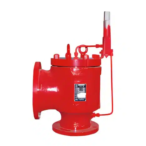
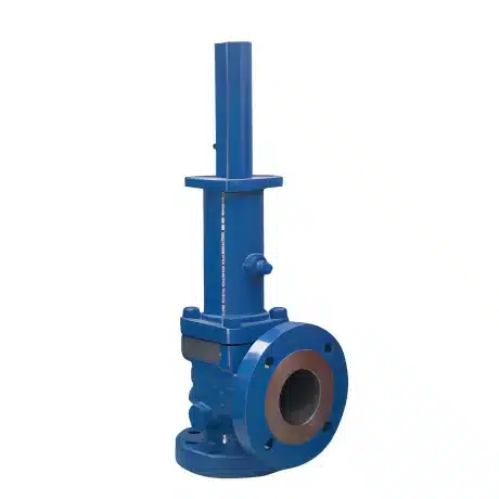
The 5212 series pilot-operated safety relief valves are mainly used in the fields of oil and gas, chemical industry, electric power, metallurgy, and natural gas. It is the best overpressure protection device for pressurized equipment, containers, or pipelines. The allowed working pressure is close to the set pressure of the safety valve. A small overpressure can quickly make the main valve reach the full opening state. This safety valve’s operating performance and opening height are not affected by back pressure.
The 5213 series is a conventional spring-type pressure relief valve. The 5213B series is a balanced piston pressure relief valve. Available for flanged, threaded end connection.
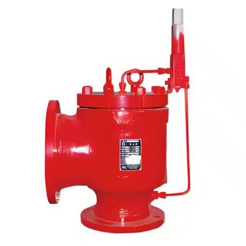
The 5214 series high-performance steam safety valve is suitable for steam overpressure protection of power boilers, once-through boilers, reheaters, and other equipment and pipelines. Designed and manufactured according to ASME I standards
The 5215 series safety valve is used as an overpressure protection device where the medium needs to be insulated in polyester, ethylene, asphalt, and urea fertilizer equipment. The 5215B is a bellows structure designed for thermal insulation jacket safety valve.
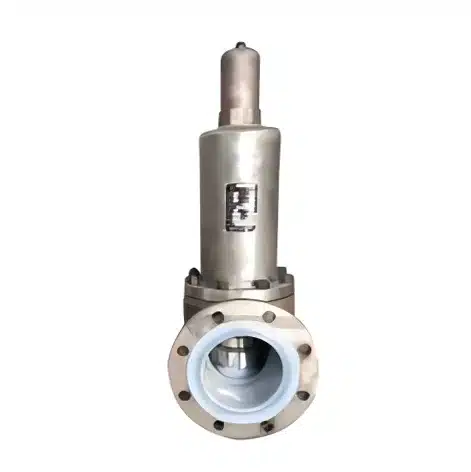
The 5216 series is a lined bellows safety valve. The main parts in the valve that are in contact with the medium are lined with fluorine material. The special bellows design is suitable for highly corrosive working conditions such as salt water, wet chlorine, hydrochloric acid, sulfuric acid, etc. According to the medium working conditions, the lining can be made of F46, PTFE, PFA, and other materials.
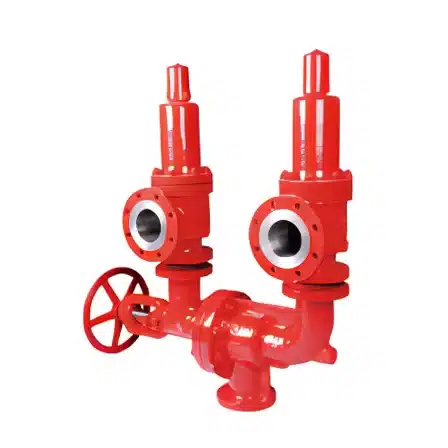
The 5217 series consists of a switching valve and two safety valves. The safety valve can be replaced or repaired without stopping the device. Double switching valve group linkage control can be used as needed.
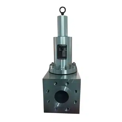
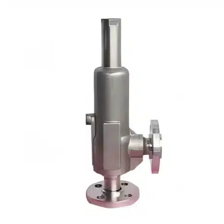
The 5218 series forged safety valves are mainly used for special working conditions that cannot be met by casting steel. According to the medium working conditions, the lining can be made of A105, SS304, SS316, Monel, Hastelloy, and other materials.
This detailed study explores the process of determining the appropriate size for various applications. It includes equations for sizing according to AD Merkblatt, DIN, TRD, ASME, API, BS6759, and other relevant standards. The study also addresses more intricate topics like two-phase flow and superheat.
The sizing of a safety valve is of utmost importance to ensure its ability to release steam from any source effectively, thus preventing the pressure within the protected equipment from exceeding the maximum allowable accumulated pressure (MAAP). To achieve this, proper positioning and correct valve setting are crucial. Additionally, the safety valve must be appropriately sized to allow the necessary amount of steam to pass at the required pressure, even during various potential fault scenarios.
Once the specific safety valve type, set pressure, and location within the system have been determined, it becomes necessary to calculate the required discharge capacity of the valve. This calculation enables us to ascertain the necessary orifice area and nominal size based on the specifications provided by the manufacturer.
To establish the maximum capacity needed, it is essential to consider the potential flow through all relevant branches upstream of the valve.
In cases where multiple flow paths are present, sizing the safety valve becomes more complex. Several alternative methods can be considered to determine its size in such situations. The following alternatives should be carefully evaluated:
1. Sizing the safety valve based on the maximum flow within the flow path that experiences the highest amount of flow.
2. Sizing the safety valve to accommodate the combined flow from all flow paths.
The choice between these two methods depends on the risk of multiple devices failing simultaneously. If there exists even the slightest possibility of such an occurrence, the valve must be sized to handle the combined flow from the failed devices. However, in cases where the risk is negligible, cost considerations may lead to sizing the valve based only on the highest fault flow. Ultimately, it falls under the responsibility of the company ensuring the plant to decide which method to employ.
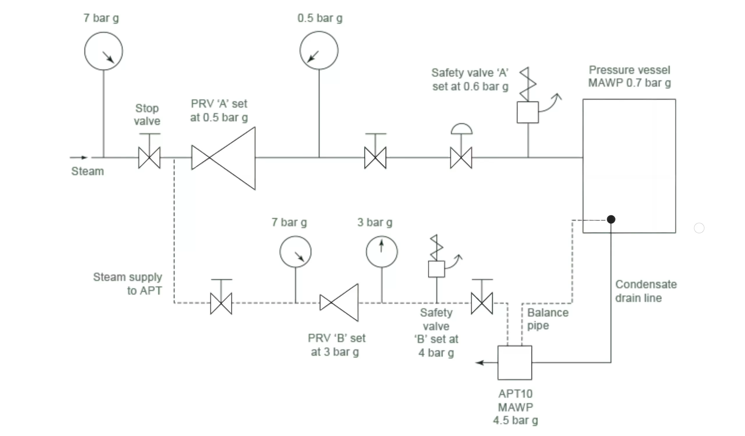
To illustrate, let us consider the pressure vessel and automatic pump-trap (APT) system depicted in the following Figure. Although unlikely, there is a scenario where both the APT and pressure reducing valve (PRV ‘A’) could fail simultaneously. In this case, the discharge capacity of safety valve ‘A’ would either need to accommodate the fault load from the largest PRV or the combined fault load from both the APT and PRV ‘A’.
It is recommended, according to this document, that whenever multiple flow paths are present, the sizing of all relevant safety valves should always consider the possibility of simultaneous failures in the upstream pressure control valves.
To ascertain the flow of faults through a Pressure Relief Valve (PRV) or any other valve or orifice, it is essential to consider the following factors:
1. The potential fault pressure: This value corresponds to the predetermined pressure at which the upstream safety valve is set.
2. The relieving pressure of the safety valve under consideration, which is being sized.
3. The maximum capacity (KVS) of the control valve located upstream, when fully open.
NWP = Normal working pressure
MAAP= Maximum allowable accumulated pressure
Ps = Safety valve set pressure
PO= Safety valve overpressure
PR = Safety valve relieving pressure
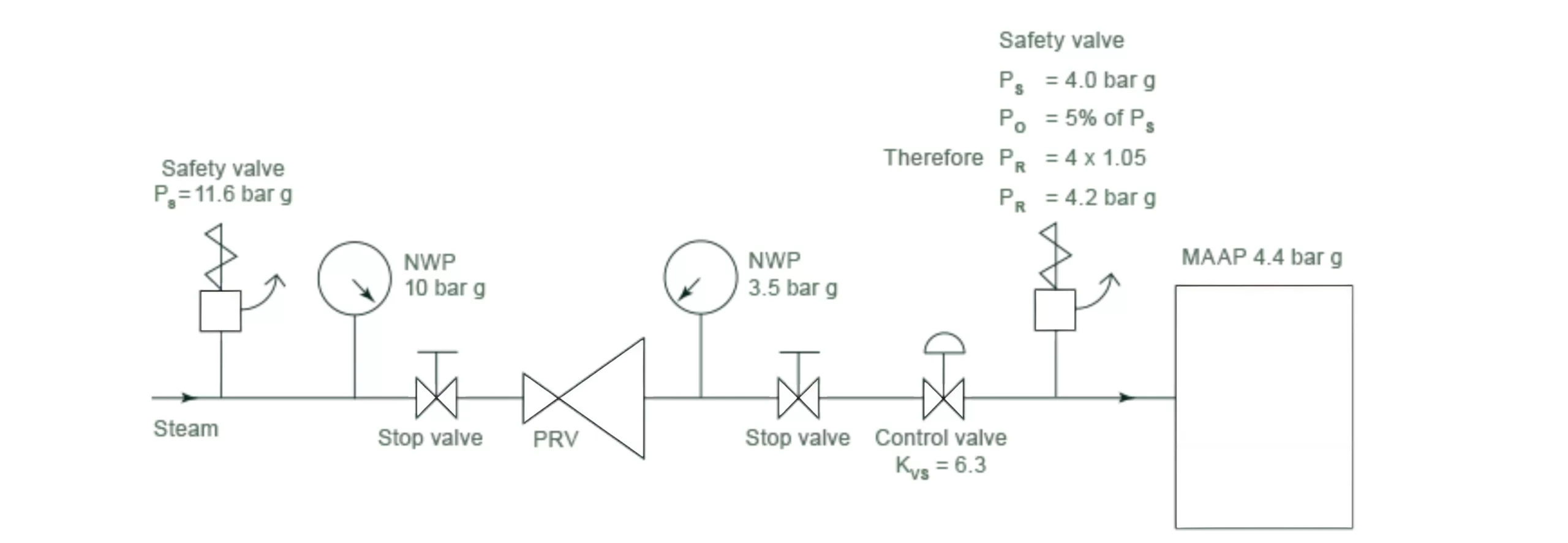
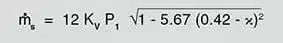
In this system, the supply pressure is constrained by an upstream safety valve set at 11.6 bar g. The flow of fault through the PRV can be calculated using the steam mass flow equation.

Where:
Ms = Fault load (kg/h)
Kv = PRV full open capacity index (Kvs = 6.3)
x = Pressure drop = (P1 – P2)/P1
P1 = Fault pressure (taken as the set pressure of the upstream safety valve)(bar a)
P2 = Relieving pressure of the apparatus safety valve (bar a)
P1 = 11.6 bar g = 12.6 bar a
P2= 4.2 bar g = 5.2 bar a
Therefore: Pressure dop = (12.6 – 5.2)/12.6 = 0.59
So we know pressure ratio 0.59 is greater than 0.42, critical pressure drop occurs across the control valve, and the fault flow is calculated as follows using the formula in Equation(e-2):
Ms = 12KvP1 = 12 x 6.3 x 12.6
Therefore: Ms = 953 kg/h
Accordingly, the safety valve should have a minimum capacity of 953 kg/h at a setting of 4 bar g.
Once the fault load has been determined, it is generally adequate to determine the size of the safety valve by referring to the capacity charts provided by the manufacturer. An illustrative capacity chart can be found in Figure f(typical safety valve capacity chart). By knowing the required set pressure and discharge capacity, it is possible to choose an appropriate nominal size. In this case, with a set pressure of 4 bar g and a fault flow of 953 kg/h, a DN32/50 safety valve should be selected, which has a capacity of 1,284 kg/h.
SV615 flow capacity for saturated steam in kilogrammes per hour (kg/h)(calculated in accordance with EN ISO 4126 at 5%overpressure)Derated coefficient of discharge (K)=0.71 | ||||||
| Valve size DN | 15/20 | 20/32 | 25/40 | 32/50 | 40/65 | 50/80 |
| Area(mm²) | 113 | 314 | 452 | 661 | 1.075 | 1662 |
| Set pressure (bar g) | Flow capacity for saturated steam kg/h | |||||
| 0.5 | 65 | 180 | 259 | 379 | 616 | 953 |
| 1.0 | 87 | 241 | 348 | 508 | 827 | 1278 |
| 1.5 | 109 | 303 | 436 | 638 | 1037 | 1603 |
| 2.0 | 131 | 364 | 524 | 767 | 1247 | 1929 |
| 2.5 | 153 | 426 | 613 | 896 | 1458 | 2254 |
| 3.0 | 175 | 487 | 701 | 1026 | 1668 | 2579 |
| 3.5 | 197 | 549 | 790 | 1155 | 1879 | 2904 |
| 4.0 | 220 | 610 | 878 | 1284 | 2089 | 3230 |
| 4.5 | 242 | 672 | 967 | 1.414 | 2299 | 3555 |
| 5.0 | 264 | 733 | 1055 | 1543 | 2510 | 3880 |
| 5.5 | 286 | 794 | 1144 | 1672 | 2720 | 4205 |
| 6.0 | 308 | 856 | 1232 | 1802 | 2930 | 4530 |
| 6.5 | 330 | 917 | 1321 | 1931 | 3141 | 4856 |
| 7.0 | 352 | 979 | 1409 | 2061 | 3351 | 5181 |
| 7.5 | 374 | 1.040 | 1497 | 2190 | 3561 | 5506 |
| 8.0 | 396 | 1102 | 1586 | 2319 | 3772 | 5831 |
In cases where sizing charts are absent or insufficient for specific fluids or conditions like backpressure, high viscosity, or two-phase flow, it becomes necessary to compute the minimum orifice area needed. The appropriate governing standards, such as ASME/API RP 520 and EN ISO 4126, provide guidance on the methods to accomplish this.
These methods rely on the coefficient of discharge, which represents the measured capacity relative to the theoretical capacity of a nozzle with an equivalent flow area.
where:
Kd = Coefficient of discharge
The coefficient of discharge is specific to the safety valve range and is determined and approved by the manufacturer. If the valve is independently approved, it is assigned a certified coefficient of discharge.
To obtain a derated coefficient of discharge, the certified coefficient is often multiplied by a safety factor of 0.9. This derated coefficient is denoted as Kdr = Kd x 0.9.
When calculating the required orifice area using standard methods, the following considerations should be taken into account:
The flow of gas or vapor through an orifice, such as the flow area of a safety valve, increases as the downstream pressure decreases. This relationship holds true until the critical pressure is reached, resulting in critical flow. Beyond this point, further decrease in the downstream pressure will not lead to increased flow. Equation (g-1) represents the critical pressure ratio that exists between the critical pressure and the actual relieving pressure for gases flowing through safety valves.

where:
PB = Critical backpressure (bar a)
P1 = Actual relieving pressure (bar a)
k = isentropic coefficient of the gas or vapor at the relieving conditions
To properly size a valve, it is crucial to determine the design overpressure beforehand. It is not acceptable to calculate the valve’s capacity using an overpressure lower than the one used to establish the coefficient of discharge. However, it is permissible to employ a higher overpressure value. In the case of DIN type full lift valves, the design lift should be attained at 5% overpressure, but for sizing purposes, a 10% overpressure value may be utilized.
The minimum required orifice area for a safety valve can be determined using the methods outlined in widely used national standards.
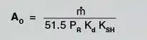
Specifically, the ASME standards and API RP 520 guidelines provide formulae that enable the calculation of this area. For steam applications, Equation (h-1) should be utilized for this purpose.
Where:
Ao = Required effective discharge area (in2)
M = Required mass flow through the valve (Ib/h)
PR = Upstream relieving pressure (psi a)
Kd = Effective coefficient of discharge (specified by the manufacturer)
KsH = Superheat correction factor
| Set pressure (psi g) | Temperature (°F) | |||||||||
| 300 | 400 | 500 | 600 | 700 | 800 | 900 | 1 000 | 1 100 | 1 200 | |
| 15 | 1 | 0.98 | 0.93 | 0.88 | 0.84 | 0.8 | 0.77 | 0.74 | 0.72 | 0.7 |
| 20 | 1 | 0.98 | 0.93 | 0.88 | 0.84 | 0.8 | 0.77 | 0.74 | 0.72 | 0.7 |
| 40 | 1 | 0.99 | 0.93 | 0.88 | 0.84 | 0.81 | 0.77 | 0.74 | 0.72 | 0.7 |
| 60 | 1 | 0.99 | 0.93 | 0.88 | 0.84 | 0.81 | 0.77 | 0.75 | 0.72 | 0.7 |
| 80 | 1 | 0.99 | 0.93 | 0.88 | 0.84 | 0.81 | 0.77 | 0.75 | 0.72 | 0.7 |
| 100 | 1 | 0.99 | 0.94 | 0.89 | 0.84 | 0.81 | 0.77 | 0.75 | 0.72 | 0.7 |
| 120 | 1 | 0.99 | 0.94 | 0.89 | 0.84 | 0.81 | 0.78 | 0.75 | 0.72 | 0.7 |
| 140 | 1 | 0.99 | 0.94 | 0.89 | 0.85 | 0.81 | 0.78 | 0.75 | 0.72 | 0.7 |
| 160 | 1 | 0.99 | 0.94 | 0.89 | 0.85 | 0.81 | 0.78 | 0.75 | 0.72 | 0.7 |
| 180 | 1 | 0.99 | 0.94 | 0.89 | 0.85 | 0.81 | 0.78 | 0.75 | 0.72 | 0.7 |
| 200 | 1 | 0.99 | 0.95 | 0.89 | 0.85 | 0.81 | 0.78 | 0.75 | 0.72 | 0.7 |
| 220 | 1 | 0.99 | 0.95 | 0.89 | 0.85 | 0.81 | 0.78 | 0.75 | 0.72 | 0.7 |
| 240 | 1 | 0.95 | 0.9 | 0.85 | 0.81 | 0.78 | 0.75 | 0.72 | 0.7 | |
| 260 | 1 | 0.95 | 0.9 | 0.85 | 0.81 | 0.78 | 0.75 | 0.72 | 0.7 | |
| 280 | 1 | 0.96 | 0.9 | 0.85 | 0.81 | 0.78 | 0.75 | 0.72 | 0.7 | |
| 300 | 1 | 0.96 | 0.9 | 0.85 | 0.81 | 0.78 | 0.75 | 0.72 | 0.7 | |
| 350 | 1 | 0.96 | 0.9 | 0.86 | 0.82 | 0.78 | 0.75 | 0.72 | 0.7 | |
| 400 | 1 | 0.96 | 0.91 | 0.86 | 0.82 | 0.78 | 0.75 | 0.72 | 0.7 | |
| 500 | 1 | 0.96 | 0.92 | 0.86 | 0.82 | 0.78 | 0.75 | 0.73 | 0.7 | |
| 600 | 1 | 0.97 | 0.92 | 0.87 | 0.82 | 0.79 | 0.75 | 0.73 | 0.7 | |
| 800 | 1 | 0.95 | 0.88 | 0.83 | 0.79 | 0.76 | 0.73 | 0.7 | ||
| 1 000 | 1 | 0.96 | 0.89 | 0.84 | 0.78 | 0.76 | 0.73 | 0.71 | ||
| 1 250 | 1 | 0.97 | 0.91 | 0.85 | 0.8 | 0.77 | 0.74 | 0.71 | ||
| 1 500 | 1 | 1 | 0.93 | 0.86 | 0.81 | 0.77 | 0.74 | 0.71 | ||
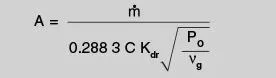
To determine the minimum orifice area needed for a safety valve operating with dry saturated steam (with a dryness fraction greater than 0.98) and superheated steam under critical flow conditions, Equation (h-2) should be used.
Please refer to Equation (h-3) for calculating the minimum orifice area necessary for a safety valve in wet steam applications where critical flow occurs. It is important to note that wet steam should have a dryness fraction exceeding 0.9.
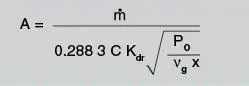
where:
A = Flow area (not curtain area) mm2
M = Mass flowrate (kg/h)
C = Function of the isentropic exponent
Kdr = Certified derated coefficient of discharge (from manufacturer)
Po = Relieving pressure (bar a)
Vg = Specific volume at relieving pressure and temperature(m3/kg)(from steam tables)
x = Dryness fraction of wet steam
| k | Cg |
| 0.4 | 1.647 |
| 0.41 | 1.665 |
| 0.42 | 1.682 |
| 0.43 | 1.7 |
| 0.44 | 1.717 |
| 0.45 | 1.733 |
| 0.46 | 1.75 |
| 0.47 | 1.766 |
| 0.48 | 1.782 |
| 0.49 | 1.798 |
| 0.5 | 1.813 |
| 0.51 | 1.829 |
| 0.52 | 1.844 |
| 0.53 | 1.858 |
| 0.54 | 1.873 |
| 0.55 | 1.888 |
| 0.56 | 1.902 |
| 0.57 | 1.916 |
| 0.58 | 1.93 |
| 0.59 | 1.944 |
| 0.6 | 1.957 |
| 0.61 | 1.971 |
| 0.62 | 1.984 |
| 0.63 | 1.997 |
| 0.64 | 2.01 |
| 0.65 | 2.023 |
| 0.66 | 2.035 |
| 0.67 | 2.048 |
| 0.68 | 2.06 |
| 0.69 | 2.072 |
| 0.7 | 2.084 |
| 0.71 | 2.096 |
| 0.72 | 2.108 |
| 0.73 | 2.12 |
| 0.74 | 2.131 |
| 0.75 | 2.143 |
| 0.76 | 2.154 |
| 0.77 | 2.165 |
| 0.78 | 2.17 |
| 0.79 | 2.187 |
| 0.8 | 2.198 |
| 0.81 | 2.209 |
| 0.82 | 2.219 |
| 0.83 | 2.23 |
| 0.84 | 2.24 |
| 0.85 | 2.251 |
| 0.86 | 2.261 |
| 0.87 | 2.271 |
| 0.88 | 2.281 |
| 0.89 | 2.291 |
| 0.9 | 2.301 |
| 0.91 | 2.311 |
| 0.92 | 2.32 |
| 0.93 | 2.33 |
| 0.94 | 2.339 |
| 0.95 | 2.349 |
| 0.96 | 2.358 |
| 0.97 | 2.367 |
| 0.98 | 2.376 |
| 0.99 | 2.386 |
| 1 | 2.401 |
| 1.01 | 2.404 |
| 1.02 | 2.412 |
| 1.03 | 2.421 |
| 1.04 | 2.43 |
| 1.05 | 2.439 |
| 1.06 | 2.447 |
| 1.07 | 2.456 |
| 1.08 | 2.464 |
| 1.09 | 2.472 |
| 1.1 | 2.481 |
| 1.11 | 2.489 |
| 1.12 | 2.497 |
| 1.13 | 2.505 |
| 1.14 | 2.513 |
| 1.15 | 2.521 |
| 1.16 | 2.529 |
| 1.17 | 2.537 |
| 1.18 | 2.545 |
| 1.19 | 2.553 |
| 1.2 | 2.56 |
| 1.21 | 2.568 |
| 1.22 | 2.57 |
| 1.23 | 2.583 |
| 1.24 | 2.591 |
| 1.25 | 2.598 |
| 1.26 | 2.605 |
| 1.27 | 2.613 |
| 1.28 | 2.62 |
| 1.29 | 2.627 |
| 1.3 | 2.634 |
| 1.31 | 2.641 |
| 1.32 | 2.649 |
| 1.33 | 2.656 |
| 1.34 | 2.663 |
| 1.35 | 2.669 |
| 1.36 | 2.676 |
| 1.37 | 2.683 |
| 1.38 | 2.69 |
| 1.39 | 2.697 |
| 1.4 | 2.703 |
| 1.41 | 2.71 |
| 1.42 | 2.717 |
| 1.43 | 2.723 |
| 1.44 | 2.73 |
| 1.45 | 2.736 |
| 1.46 | 2.743 |
| 1.47 | 2.749 |
| 1.48 | 2.755 |
| 1.49 | 2.762 |
| 1.5 | 2.768 |
| 1.51 | 2.774 |
| 1.52 | 2.78 |
| 1.53 | 2.786 |
| 1.54 | 2.793 |
| 1.55 | 2.799 |
| 1.56 | 2.805 |
| 1.57 | 2.811 |
| 1.58 | 2.817 |
| 1.59 | 2.823 |
| 1.6 | 2.829 |
| 1.61 | 2.843 |
| 1.62 | 2.84 |
| 1.63 | 2.846 |
| 1.64 | 2.852 |
| 1.65 | 2.858 |
| 1.66 | 2.863 |
| 1.67 | 2.869 |
| 1.68 | 2.874 |
| 1.69 | 2.88 |
| 1.7 | 2.886 |
| 1.71 | 2.891 |
| 1.72 | 2.897 |
| 1.73 | 2.902 |
| 1.74 | 2.908 |
| 1.75 | 2.913 |
| 1.76 | 2.918 |
| 1.77 | 2.924 |
| 1.78 | 2.929 |
| 1.79 | 2.934 |
| 1.8 | 2.94 |
| 1.81 | 2.945 |
| 1.82 | 2.95 |
| 1.83 | 2.955 |
| 1.84 | 2.96 |
| 1.85 | 2.965 |
| 1.86 | 2.971 |
| 1.87 | 2.976 |
| 1.88 | 2.981 |
| 1.89 | 2.986 |
| 1.9 | 2.991 |
| 1.91 | 2.996 |
| 1.92 | 3.001 |
| 1.93 | 3.006 |
| 1.94 | 3.01 |
| 1.95 | 3.015 |
| 1.96 | 3.02 |
| 1.97 | 3.025 |
| 1.98 | 3.03 |
| 1.99 | 3.034 |
| 2 | 3.039 |
| 2.01 | 3.044 |
| 2.02 | 3.049 |
| 2.03 | 3.053 |
| 2.04 | 3.058 |
| 2.05 | 3.063 |
| 2.06 | 3.067 |
| 2.07 | 3.072 |
| 2.08 | 3.076 |
| 2.09 | 3.081 |
| 2.1 | 3.085 |
| 2.11 | 3.09 |
| 2.12 | 3.094 |
| 2.13 | 3.099 |
| 2.14 | 3.103 |
| 2.15 | 3.107 |
| 2.16 | 3.112 |
| 2.17 | 3.116 |
| 2.18 | 3.121 |
| 2.19 | 3.125 |
| 2.2 | 3.129 |
Important considerations for the installation of safety valves encompass handling, plant conditions, pipework configuration, markings, and noise considerations.
The seat tightness of a safety valve holds significance during the selection and installation process. Inadequate seat tightness can result in a continuous loss of system fluid and also lead to the deterioration of sealing faces, thereby causing premature lifting of the valve.
The seat tightness is influenced by three primary factors: the characteristics of the safety valve, the installation method employed, and the operation of the safety valve.
Regarding the safety valve’s characteristics, to ensure satisfactory shut-off in a metal-seated valve, the sealing surfaces must possess a high degree of flatness with an excellent surface finish. The disc should articulate on the stem without encountering excessive frictional effects from the stem guide. For the metal-seated valve, acceptable shut-off typically requires a surface finish of 0.5 μm and a flatness level of two optical light bands. Additionally, the mating and sealing surfaces must exhibit high wear resistance to extend the valve’s service life.
Unlike regular isolation valves, the closing force acting on the disc in a safety valve is relatively small due to the minimal difference between the system pressure on the disc and the opposing spring force.
In some instances, resilient or elastomer seals are integrated into the valve discs to enhance shut-off. However, it is important to note that soft seals are often more vulnerable to damage compared to metal seats.
During safety valve installation, seat damage can occur when the valve is initially lifted as part of the general plant commissioning procedure, mainly because dirt and debris are frequently present in the system. Flushing the system before valve installation and ensuring that the valve is mounted in a location where dirt, scale, and debris cannot accumulate help prevent the passage of foreign matter through the valve.
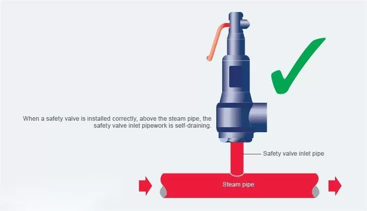
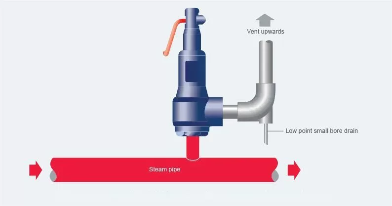
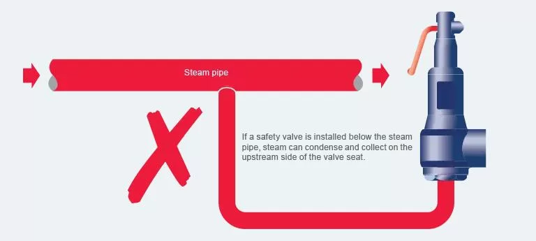
For steam applications, it is crucial to minimize the potential for leakage by positioning the valve in a way that prevents condensate from collecting on the upstream side of the disc. This can be achieved by installing the safety valve above the steam pipe, as illustrated in Figure(h-4).
Leakage may occur due to the presence of dirt or scale on the seating face. This commonly happens during periodic lifting required by insurance companies and routine maintenance programs. By further lifting the lever, any dirt on the seating face can generally be cleared.
The majority of safety valve seat leakage issues arise after the initial manufacturing and testing phase. These problems typically stem from damage during transportation, occasionally due to misuse and contamination, or as a result of poor installation.
Most safety valve standards do not provide detailed shut-off parameters. However, for those that do, the requirements and recommended test procedures are generally based on the widely used API 527 standard within the safety valve industry.
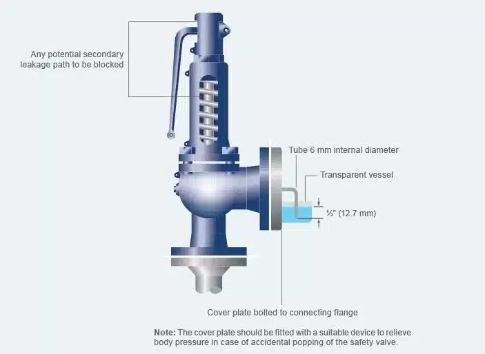
To test valves set on air, it is necessary to block all secondary leakage paths while maintaining the valve at 90% of the set pressure on air (refer to Figure h-6). The outlet of the safety valve is connected to a 6 mm internal diameter pipe, with its end positioned 12.7 mm below the surface of water contained in a suitable transparent vessel. The number of bubbles discharged per minute from this tube is measured. For valves set below 70 bar g, the acceptance criterion is 20 bubbles per minute for most cases.
When dealing with valves intended for steam or water applications, it is important to evaluate the leakage rate by utilizing the corresponding medium. In the case of steam, it is crucial to ensure that no visible leakage is observed against a black background for a duration of one minute following a stabilization period of three minutes. However, for water, a minor allowance for leakage exists, which is dependent on the orifice area. This allowance amounts to 10 ml per hour per inch of the nominal inlet diameter.
Given the potentially time-consuming nature of the aforementioned procedure, it is common practice for manufacturers to employ alternative methods of testing. One such method involves the use of precise flow measuring equipment, which is calibrated in accordance with the parameters outlined in API 527.
The ASME (American Society of Mechanical Engineers) Boiler and Pressure Vessel Code (BPVC) Section VIII deals with the design, construction, and maintenance of pressure vessels and boilers. It includes specific requirements and guidelines for safety valves, which are critical for ensuring the safe operation of pressure vessels. Here are the key aspects of ASME VIII concerning safety valves:
The set pressure is the pressure at which the safety valve begins to open. ASME VIII requires that safety valves should be set to open at a pressure no higher than the maximum allowable working pressure (MAWP) of the vessel. Overpressure is the increase in pressure over the set pressure, usually a small percentage, allowing for the valve to fully open.
Safety valves must have sufficient capacity to discharge all the steam or fluid that can be generated by the vessel to maintain the pressure at or below the MAWP. The sizing of the safety valve is crucial and must be calculated based on specific formulas and conditions.
This refers to the pressure increase over the MAWP of the vessel when the safety valve is discharging. Accumulation is limited by ASME VIII to ensure that the vessel can withstand the pressure until the valve returns to its closed position.
The difference between the set pressure at which the valve opens and the pressure at which it re-closes. Blowdown prevents the safety valve from chattering – opening and closing rapidly.
ASME VIII provides specific requirements for the installation of safety valves, including the orientation (they should be installed vertically), and no intervening shutoff valves between the safety valve and the vessel.
Safety valves must be regularly inspected and tested to ensure they operate correctly at the set pressure and are in good condition. This includes both bench testing (off the vessel) and in-situ testing (on the vessel).
The materials used for safety valves must be suitable for the process fluid and operating conditions. The construction should ensure reliability and durability under operating conditions.
Safety valves should be clearly marked with the set pressure, MAWP, capacity, manufacturer’s name, and other essential data. They must also meet the certification and quality standards outlined in ASME VIII.
Regular maintenance is crucial for safety valve performance. This includes periodic checking, cleaning, and replacing of parts as needed. Proper maintenance ensures that the valve will operate as intended during overpressure conditions.
In industries where chemicals are processed under high pressure, adherence to ASME VIII is crucial for preventing overpressure incidents.
Safety valves designed according to ASME VIII standards are essential in the oil and gas industry, particularly in offshore rigs and refineries.
In power plants, especially those using steam turbines, safety valves must conform to these standards to handle high-pressure steam safely.
Safety valves must be made of materials that are non-reactive and easy to clean, and their design should prevent any contamination of the pharmaceutical products.
Safety valves in the Food and Beverage industry must meet high standards of hygiene, be made of appropriate materials, and be capable of withstanding the specific pressures and temperatures encountered in food processing and storage.
Safety valves for the Marine industry are specifically designed to cope with harsh marine environments, limited space, regulatory compliance, and the need for high reliability and low maintenance.
In the Pulp and Paper industry, safety valves must be highly resistant to corrosion and abrasion due to the exposure to chemicals and particulates, capable of handling high pressure and temperature variations, and compliant with industry-specific safety and environmental regulations.
Safety valves in the mining industry must be highly durable, capable of withstanding harsh and potentially abrasive environments, and compliant with strict safety standards to ensure reliable overpressure protection in equipment such as compressed air systems, chemical processing units, and hydraulic systems.
In Water and Wastewater Treatment, safety valves must be highly resistant to corrosion, able to handle varying types of fluids, and comply with environmental and public health regulations, ensuring reliable pressure control in diverse treatment processes.
In HVAC systems, safety valves must be designed to reliably operate in varying temperature and pressure conditions, ensuring overpressure protection while being compatible with refrigerants used in the system.
In cryogenics, safety valves must be designed to operate reliably at extremely low temperatures, using materials and seals that can withstand such conditions without losing their integrity or functionality.
Safety valves in the Aerospace and Defense industry must be exceptionally reliable, precisely calibrated for specific pressure ranges, and constructed from materials capable of withstanding extreme temperatures, pressures, and corrosive environments, while also complying with stringent aerospace standards for safety and performance.
Safety valves are critical components in various industrial systems, ensuring safety and operational efficiency. Here are some frequently asked questions (FAQs) about safety valves:
A safety valve is an automatic pressure-relieving device, actuated by the static pressure upstream of the valve. It’s designed to open rapidly (pop action) to prevent an unsafe rise in pressure within a system, typically used for gas or vapor service.
Safety valves operate by releasing excess pressure from a system once it reaches a predefined limit. The valve opens when the force due to the pressure of the fluid (gas, vapor, or liquid) exceeds the opposing force exerted by a spring or weight. Once the pressure drops to a safe level, the valve closes automatically.
Safety valves should be tested periodically to ensure they function correctly. The testing frequency depends on the valve’s application, operating conditions, and regulatory requirements. It’s generally recommended to conduct tests annually.
Set pressure, also known as opening pressure, is the predetermined pressure at which a safety valve starts to open under operating conditions.
No, safety valves are designed for specific mediums (gas, vapor, or liquid) and operating conditions. Using a safety valve for an unsuitable medium can lead to malfunction or failure.
The capacity of a safety valve is determined based on the system’s maximum allowable working pressure (MAWP), the type of fluid, flow characteristics, and the valve’s discharge coefficient.
Blowdown is the difference between the set pressure at which the valve opens and the reseating pressure where the valve closes, usually expressed as a percentage of the set pressure.
Common issues include seat leakage, improper sizing, valve chatter, and bellows failure. Regular maintenance and inspection are essential to address these problems.
Selection involves considering factors like the type of fluid, operating pressure and temperature, discharge capacity, and the system’s design requirements. Compliance with relevant standards (e.g., API, ISO) is also crucial.
In many industrial applications, particularly involving pressurized systems like boilers and chemical plants, safety valves are mandatory for compliance with safety regulations.
Here’s a simplified troubleshooting guide for safety valves from THINKTANK, it will help you in quickly diagnosing and addressing common issues.
Issue | PossibleCauses | Suggested Actions |
|---|---|---|
| Valve Fails to Open at Set Pressure | – Incorrect set pressure – Blockage in inlet or outlet – Sticking due to corrosion or debris | – Recalibrate set pressure – Inspect and clear blockages – Clean and lubricate moving parts |
| Valve Leaks or Does Not Close Fully | – Seat damage – Foreign particles on seat – Spring fatigue or damage | – Inspect and repair seat – Clean seat and disc – Replace or adjust spring |
| Excessive Blowdown | – Incorrect blowdown setting – Worn seat or disc – Improperly seated valve | – Adjust blowdown setting – Inspect and replace worn parts – Reinstall or reseat valve correctly |
| Premature Opening | – Set pressure too low – System pressure fluctuations – Mechanical vibrations | – Adjust set pressure – Stabilize system pressure – Isolate valve from vibrations |
| Chattering | – Valve oversized for the application – High backpressure – Inadequate spring tension | – Resize or replace with correct valve – Reduce backpressure – Adjust spring tension |
| Rapid Cycling | – Fluctuating system pressures – Improperly sized valve – Bellows failure (if applicable) | – Stabilize system pressure – Resize valve – Inspect and replace bellows |
| Unusual Noise | – Turbulence in discharge – Mechanical resonance – Damaged valve components | – Inspect discharge path – Adjust valve installation – Replace damaged parts |
| External Leakage | – Gasket failure – Loose flanges or fittings – Corrosion or erosion | – Replace gaskets – Tighten flanges and fittings – Inspect and address corrosion |
| Inspect Item | Safety Valve Quality Grade | |||||||
| Qualified Product | First-Class Product | Superior Product | ||||||
| Shell Hydraulic Test | Test Medium | Water | ||||||
| Test Pressure( MPa) | Designed and Manufactured Refer to Standard GB/T 12241 | The test pressure value at the inlet is 1.5 times the design pressure at the inlet, and the test pressure value at the outlet is 1.5 times the maximum back pressure at the outlet. | ||||||
| Designed and Manufactured Refer to Standard NB/T 47063 | The test pressure value at the inlet is 1.5 times the design pressure at the inlet, and the test pressure value at the outlet is 1.5 times the maximum allowable working pressure at a temperature of 38°C for the pressure rating of the outlet flange. | |||||||
| Duration (where ‘t’ is the time specified for the duration test in GB/T 12241 or NB/T 47063) | ≥ t | ≥ 2t | ≥ 3t | |||||
| Acceptance Criteria | No visible leakage and structural damage | |||||||
| Performance Test | Performance Test Medium | Steam Valve | Saturated Steam | |||||
| Gas Valve | Air or Nitrogen | |||||||
| Liquid Valve | Water | |||||||
| Set Pressure and Deviation | Set Pressure Ps(MPa) | Set Pressure as Specified in the Contract | ||||||
| Set Pressure Deviation | Safety Valve for Pressure Vessels and Pipelines | Ps≤0.5 | ±0.015 | |||||
| Ps>0.5 | ±3%Ps | ±2.7%Ps | ±2.4%Ps | |||||
| Safety Valve for Steam Boilers | Ps≤0.5 | ±0.015 | ||||||
| 0.5<Ps≤2.3 | ±3%Ps | ±2.7%Ps | ±2.4%Ps | |||||
| 2.3<Ps≤7.0 | ±0.07 | ±0.063 | ±0.056 | |||||
| Ps>7.0 | ±1%Ps | ±0.9%Ps | ±0.8%Ps | |||||
| Excess Pressure | Safety Valve for Steam | Safety Valve for Boilers | 3% | 2% | 1% | |||
| Safety Valve for Other Steam Equipment | 3% | |||||||
| Safety Valve for Gas | 10% | |||||||
| Safety Valve for Liquid | 20% | 12% | 10% | |||||
| Opening and Closing Differential Pressure (MPa) | Safety Valve for Steam Power Boilers | ≤7%Ps | ≤6%Ps | ≤4%Ps | ||||
| Safety Valve for Once-through Boilers, Reheaters, and Other Steam Equipment | Ps≤0.4 | ≤0.04 | ||||||
| Ps>0.4 | ≤10%Ps | ≤8%Ps | ≤6%Ps | |||||
| Safety Valve for Gas | Ps≤0.2 | ≤0.03 | ||||||
| Ps>0.2 | ≤15%Ps | ≤10%Ps | ≤7%Ps | |||||
| Safety Valve for Liquid | Ps≤0.3 | ≤0.06 | ||||||
| Ps>0.3 | ≤20%Ps | ≤17%Ps | ≤15%Ps | |||||
| Lift Height | Must meet the requirements of GB/T 12243 and the manufacturer’s specifications. | |||||||
| Mechanical Characteristics | The safety valve operation must be stable, with no fluttering, chattering, sticking, or harmful vibrations. | |||||||
| Number of Continuous Repetitions | 3 | |||||||
| Inspect Item | Safety Valve Quality Grade | |||||||
| Qualified Product | First-Class Product | Superior Product | ||||||
| Performance Test | Sealing Test | Safety Valve for Steam | Test Pressure(MPa) | Ps≤0.3 | Ps-0.03 | |||
| Ps>0.3 | Safety Valve for Boilers | 90%Ps | 93%Ps | 96%Ps | ||||
| Safety Valve for Other Steam Equipment | 90%Ps | |||||||
| Acceptance Criteria | Inspect the outlet end of the valve visually or by listening. If no leakage is detected, the seal is considered to be satisfactory. | |||||||
| Safety Valve for Gas | Test Pressure(MPa) | Ps≤0.3 | Ps-0.03 | |||||
| Ps>0.3 | 90%Ps | |||||||
| Maximum Allowable Leakage Rate*: Number of Bubbles per Minute (Flow Path Diameter ≤16mm) | Ps≤6.9 | 40 | 20 | 10 | ||||
| 6.9<Ps≤10.3 | 60 | 30 | 10 | |||||
| 10.3<Ps≤13.8 | 80 | 40 | 15 | |||||
| 13.8<Ps≤17.2 | 100 | 50 | 20 | |||||
| 17.2<Ps≤20.7 | 100 | 50 | 20 | |||||
| 20.7<Ps≤41.4 | 100 | 50 | 25 | |||||
| Maximum Allowable Leakage Rate*: Number of Bubbles per Minute (Flow Path Diameter >16mm) | Ps≤6.9 | 20 | 12 | 10 | ||||
| 6.9<Ps≤10.3 | 30 | 15 | 10 | |||||
| 10.3<Ps≤13.8 | 40 | 20 | 10 | |||||
| 13.8<Ps≤17.2 | 50 | 25 | 10 | |||||
| 17.2<Ps≤20.7 | 60 | 30 | 15 | |||||
| 20.7<Ps≤27.6 | 80 | 40 | 20 | |||||
| 27.6<Ps≤41.4 | 100 | 50 | 20 | |||||
| Safety Valve for Liquid | Test Pressure(MPa) | Ps≤0.3 | Ps-0.03 | |||||
| Ps>0.3 | 90%Ps | |||||||
| Test Medium | Water | |||||||
| Maximum Allowable Leakage Rate*: cm3/h | DN<25mm | 10 | 9 | 8 | ||||
| DN≥25mm | 10x(DN/25) | 9x(DN/25) | 8x(DN/25) | |||||
| Note*: For safety valves with non-metallic seals used for gases and liquids, the leakage rate should be no leakage within 1 minute. | ||||||||
| Performance Test Acceptance Criteria | Within the required number of continuous repetitions, all operational performance indicators and the seal after continuous testing shall meet the corresponding grade requirements. | |||||||
WhatsApp us
Avoid your inquiry is delay response, please enter your WhatsApp/Wechat/Skype along with the message, so we can contact you at the very first time.
We will reply you within 24 hours. If for urgent case, please add WhatsApp: +86 185 1656 9221, or WeChat: +86 199 2125 0077. or call +86 189 5813 8289 directly.

We will reply you within 24 hours. If for urgent case, please add WhatsApp: +86 199 2125 0077, or WeChat: +86 199 2125 0077. Or call +86 189 5813 8289 directly.

Just leave your name, email, and simple message or requirements, We will contact you within 1 hour.
WhatsApp: +86 199 2125 0077
Skype ID: sowell85
Wechat ID: +86 199 2125 0077