


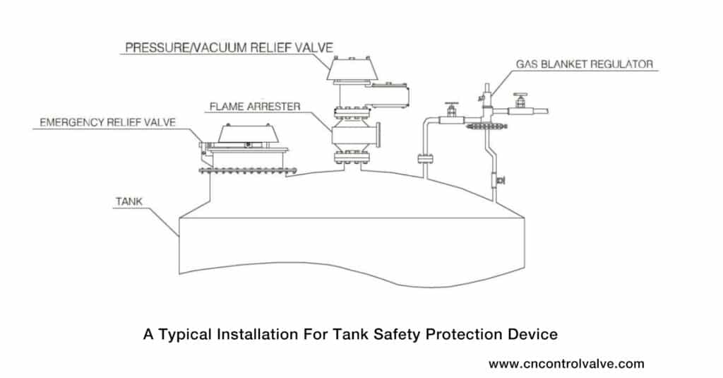
Atmospheric and low-pressure storage tanks are commonly used in the process industry. However, during operation, changes in the liquid level inside the tank or fluctuations in external temperatures can cause the gas inside the tank to either expand or contract. This leads to fluctuations in the pressure of the gas phase inside the tank, which can easily cause the tank to become over-pressurized or under-vacuumed. In severe cases, this can result in the tank becoming over-pressurized and causing buckling or under-vacuuming.
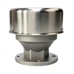
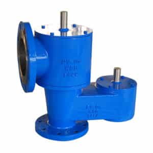
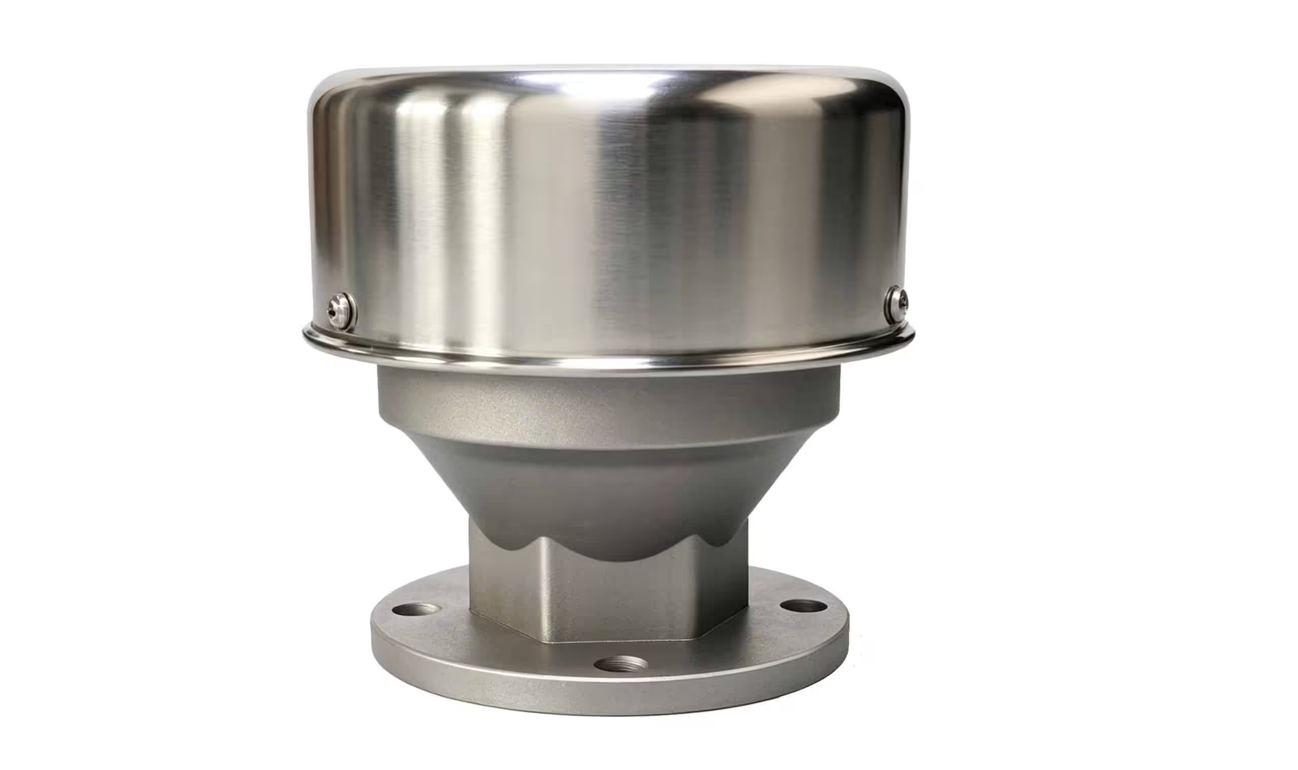
To prevent such dangerous situations, process designers typically install breather valves on the tank’s top. These valves help maintain pressure balance and ensure that the tank remains undamaged during over-pressurization or under vacuuming. By doing so, they help protect the safety of the storage tank and reduce the volatility and loss of materials inside. Furthermore, they also promote safety and environmental protection, making them a crucial component of the process industry.
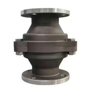
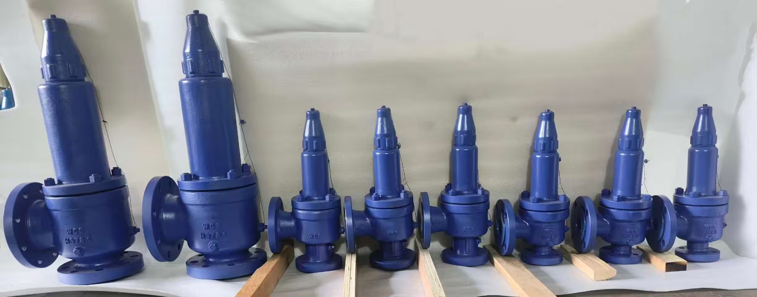
The internal structure of a breather valve is essentially composed of a pressure valve disc (exhalation valve) and a vacuum valve disc (inhalation valve), which can be arranged either side by side or overlapped.
When the pressure inside the storage tank is equal to atmospheric pressure, the valve disc and seat of both the pressure valve and vacuum valve are tightly fitted, and the sealing structure on the edge of the seat has an “adsorption” effect, ensuring that the seat is tightly sealed. When the pressure or vacuum degree increases, the valve disc begins to open, but due to the “adsorption” effect still present on the edge of the seat, a good seal can still be maintained.
When the pressure inside the tank reaches a certain value, the pressure valve is opened, and the gas inside the tank is discharged to the outside atmosphere through the exhalation valve, while the vacuum valve is closed due to the positive pressure inside the tank. Conversely, when the pressure inside the tank drops to a certain degree of vacuum, the vacuum valve is opened due to the positive pressure of the atmosphere, and outside air enters the tank through the inhalation valve, while the pressure valve is closed.
At no time can the pressure valve and vacuum valve be open at the same time. When the pressure or vacuum degree inside the tank drops to a normal operating pressure state, both the pressure valve and vacuum valve are closed, and the process of exhalation or inhalation stops.
| Common Failures | Troubleshooting |
|---|---|
| Air Leakage | Caused by corrosion, scratches on contact surface, deformation, or guide tilt. |
| Sticking | Due to improper installation or deformation of the tank, guide tilt, or rust on the valve stem. |
| Adhesion | Deposits on the valve disc, seat, and guide cause adhesion over time. |
| Clogging | Accumulation of dust, rust, or impurities in the breather valve or pipe. |
| Freezing | Water vapor in the air condenses and freezes on the valve body, disc, seat, and guide. |
| Pressure/Vacuum Valves Remaining Open | The pressure or vacuum valve remains open and fails to close. |
(1) Check for common problems such as remaining open, air leakage, sticking, jamming, clogging, freezing, and rust.
(2) Check if the seal gasket is leaking and replace if necessary.
(3) Check if the valve disc rotates flexibly and for any jamming faults.
(4) Check if the valve body seal mesh is frozen or blocked, and if there is dust or dirt attached to the mesh.
(5) Check if the valve disc, valve seat, guide, guide air spring, and other metal parts are rusted or have deposits, and clean them with kerosene.
(6) Check if the breather valve is operating normally during material inflow and outflow from the storage tank.

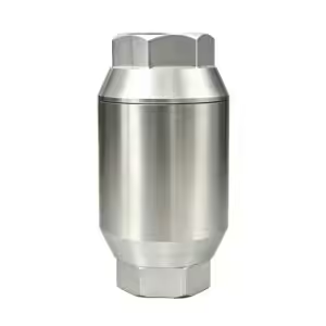
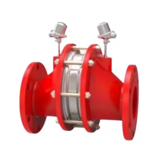
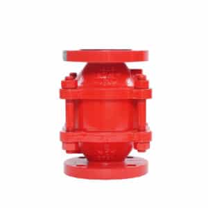
Flame arresters are safety devices used to prevent the propagation of flames in flammable gases and vapors, allowing the gas to pass through while blocking the flame. They were originally used in the petroleum industry, and have since been widely used in mining, coal mines, water transportation, and the chemical industry.
Flame arresters are mainly composed of a housing and filter element, with the filter element being the main component that prevents flame spread. Depending on the type of filter element used, flame arresters can be classified into packed-type flame arresters, plate-type flame arresters, metal mesh flame arresters, bellows flame arresters, and liquid-sealed flame arresters.
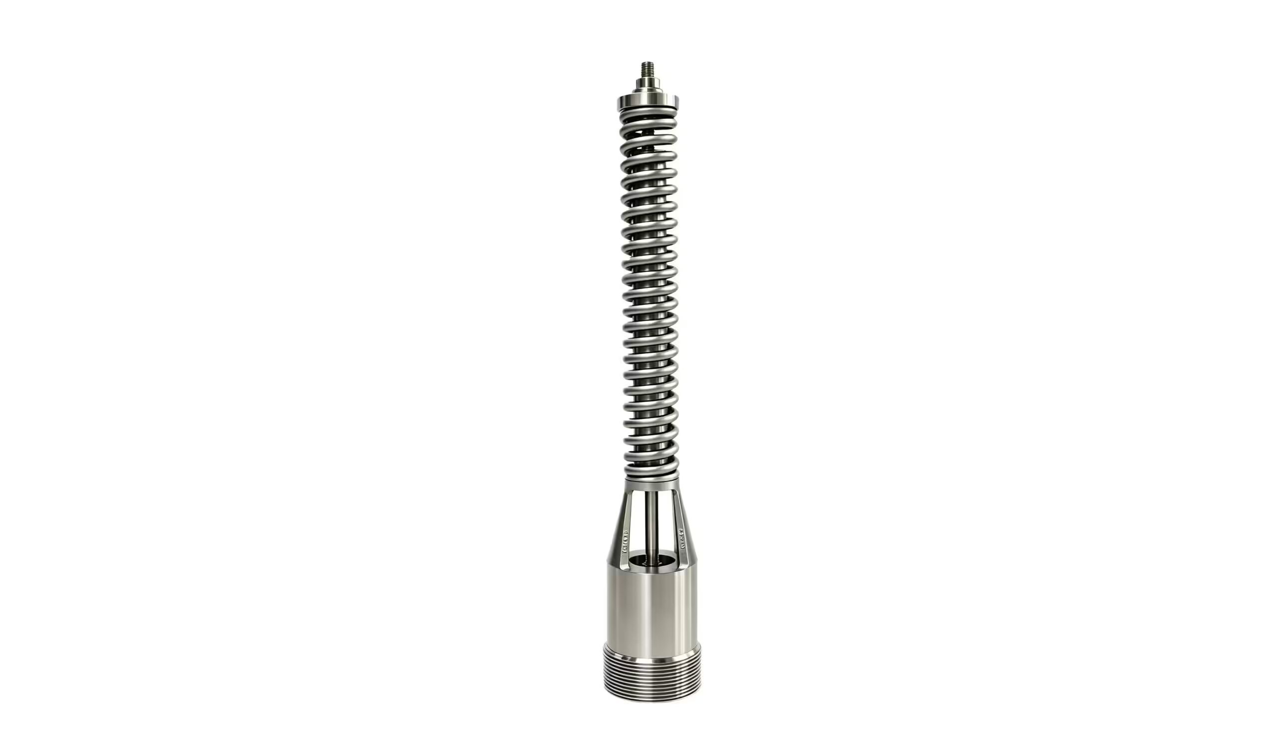
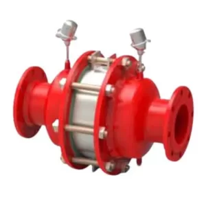
Taking the commonly used bellows flame arrester as an example, its filter element is made of thin stainless steel bellows and flat strips rolled into a disc shape (see Figure 1). Its flame-arresting ability depends only on the size of the triangular cross-sectional holes formed by the bellows on the filter element and the thickness of the filter element.


When the flame passes through the filter element, it is cut into numerous small flames by the triangular cross-sectional holes, which increases the contact area between the flame and the channel wall, enhances heat transfer, and reduces the temperature of the flame below its ignition point, thereby preventing flame spread.
Furthermore, due to the wall effect of the flame arrester, the collision probability between free radicals and the channel wall increases as the combustible gas burns through the narrow channel of the flame arrester, resulting in a decrease in the number of free radicals participating in the reaction.
When the channel of the flame arrester becomes narrow enough, the collision between the free radicals and the channel wall becomes dominant, leading to a sharp decrease in the number of free radicals and thus suppressing the spread of the flame to unburned gas.
Under certain conditions, a suitable flame arrester can effectively prevent the spread of flames. However, each type of flame arrester has its specific working range. If the operating conditions exceed this range, the flame arrester cannot guarantee its effectiveness. Therefore, flame arresters must be selected carefully.
During the selection process, the first step is to determine the location, medium type (explosion level), and operating conditions (pressure, temperature) of the flame arrester. Then, the pipeline/pipe end flame arrester is divided according to the usage scenario, and the combustion conditions are determined based on the installation position, medium type, and operating conditions to complete the preliminary selection of the flame arrester.
Based on the preliminary selection, other parameters are considered to make the final decision. These parameters include the connection method, ventilation capacity, maximum allowable pressure drop, material of the flame arrester shell/flame arrester disc, design standards, concentric/eccentric design, and whether a heating jacket is required.
In the parameters mentioned above, the working conditions that are simple can be directly determined according to the process. However, the working conditions are usually complex in actual engineering design, the medium is often a gas mixture, and the combustion conditions are diverse. Therefore, the selection of flame arresters requires careful consideration. Here we introduce two factors that influence the selection, medium type and combustion conditions.
GB 50058 “Design Code for Electrical Installations in Explosive Atmospheres” 3.4.1 states that explosive gas mixtures should be classified according to their Maximum Experimental Safe Gap (MESG) or Minimum Ignition Current Ratio (MICR).
Usually, during the selection process, the medium type is determined based on the MESG value.
According to GB 3836.11 “Explosion-proof Electrical Equipment for Explosive Environments Part 11: Equipment Protected by Flameproof Enclosures ‘d,'” under the standard test conditions, all concentrations of the tested gas or vapor in the cavity cannot ignite the maximum gap between the two parts of the inner cavity of the flameproof enclosure protected by the flameproof enclosure “d” through a 25mm long flame path.
Under conditions where the pipeline is long enough and combustion is fast enough, the flame will undergo several combustion stages in sequence, including deflagration, unstable detonation, and stable detonation (Figure 3).
In the low-pressure deflagration stage, the velocity can generally reach 112m/s, and the pressure is 0.1MPa; in the medium-pressure deflagration stage, the velocity can generally reach 20Om/s, and the pressure is 0.4MPa; in the high-pressure deflagration stage, the velocity can generally reach 30Om/s, and the pressure is 2MPa; in the detonation stage, the velocity can generally reach 1900m/s, and the pressure is 3.5MPa; in the excessive detonation stage, the velocity can generally reach 2300m/s, and the pressure is 21MPa; in the stable detonation stage, the velocity can generally reach 1830m/s, and the pressure is 35MPa.
This is because of the phenomenon of “pressure rise” that occurs during combustion. When one end of a horizontal pipeline filled with combustible gas is ignited, the flame first spread toward the pipe wall, then quickly spreads to the unignited gas, and the heat generated by combustion causes the combustion gas to rapidly expand. The expanding gas compresses the front end of the combustible gas, cause to a “pressure rise”.
The compressed gas in front of the flame front increases in density, accelerating the spread speed of combustion and increasing the heat generated during combustion. This results in a more violent “pressure rise” in front of the combustible gas. Generally, if the flame arrester is far from the ignition source, the deflagration flame may turn into a detonation flame. An increase in pressure at the front of the flame will greatly increase the risk in the pipeline, and the requirements for the flame arrester’s flame arrest and pressure resistance capabilities will be more stringent.
If the selected the wrong flame arrester, it will become a major safety hazard in production. Therefore, it is necessary to strictly select flame arresters based on the combustion conditions, whether it is a deflagration or detonation type. However, in actual engineering applications, due to the complexity of the mixed medium, pipeline conditions, and flame position, it is difficult to make clear rules for flame arrester selection under different conditions. Usually, specific analysis is conducted through the use of standards and accumulated engineering experience.
In addition, it should be noted that bends in the pipeline will accelerate the spread of flames. Therefore, this factor should be fully considered in the flame arrester selection process.
When the number of bends exceeds one, the combustion conditions become more complex, and the real situation of the pipeline needs to be simulated and tested to determine the flame arrester selection. If there are no test conditions, for safety reasons, a detonation-type flame arrester is generally required to be selected.
Therefore, under conditions allowed by the process, the number of bends between the ignition source and the flame arrester should be minimized.
THINKTANK is one of the well-known control valve manufacturers in China, which focus on control systems for over 10 years. If you are interested in the price of 3-way control valves, just feel free to contact us. <[email protected]>

Don’t risk your project with the wrong supplier. THINKTANK helps you secure better quality, faster delivery, and a long-term technical partner who speaks your language.
THINKTANK valves are already used in projects by ABB, Bray, and major EPC contractors.


WhatsApp us
Avoid your inquiry is delay response, please enter your WhatsApp/Wechat/Skype along with the message, so we can contact you at the very first time.
We will reply you within 24 hours. If for urgent case, please add WhatsApp: +86 185 1656 9221, or WeChat: +86 199 2125 0077. or call +86 189 5813 8289 directly.

Just leave your name, email, and simple message or requirements, We will contact you within 1 hour.
WhatsApp: +86 199 2125 0077
Skype ID: sowell85
Wechat ID: +86 199 2125 0077

We will reply you within 24 hours. If for urgent case, please add WhatsApp: +86 199 2125 0077, or WeChat: +86 199 2125 0077. Or call +86 189 5813 8289 directly.