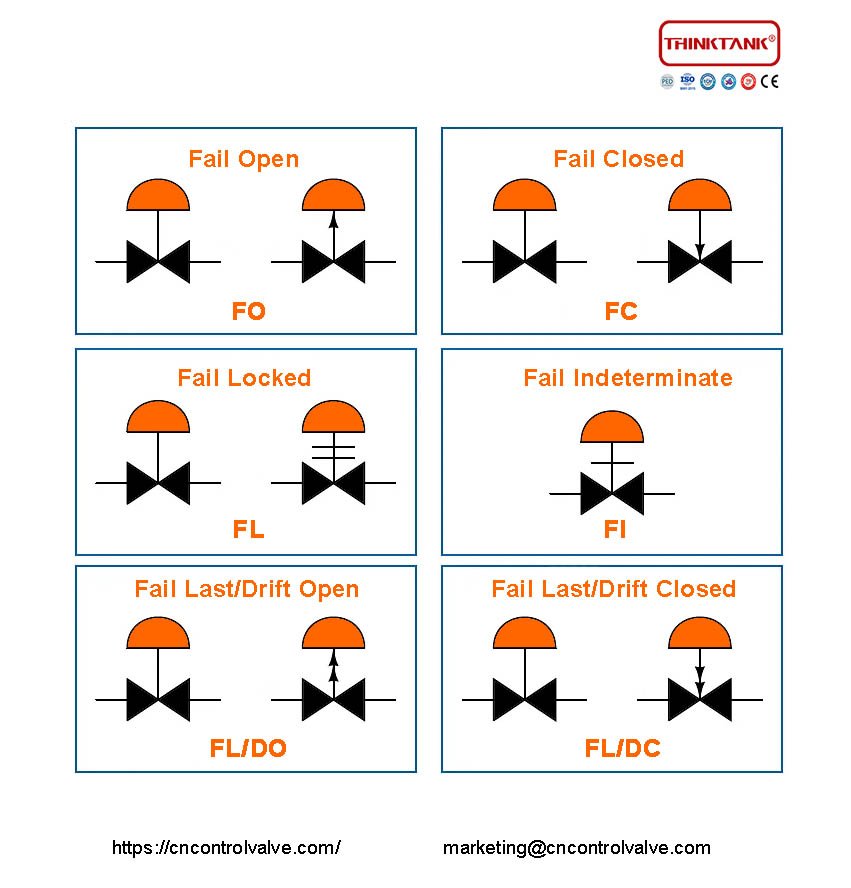
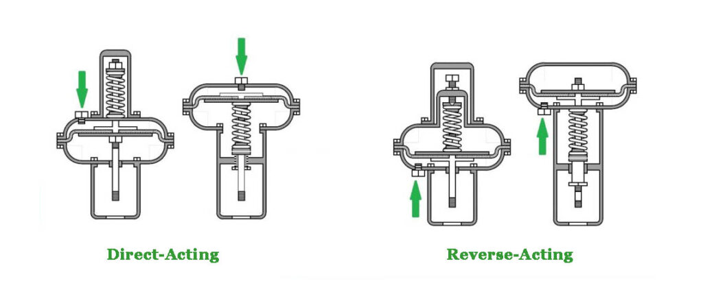
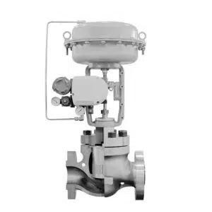
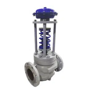
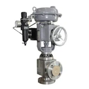
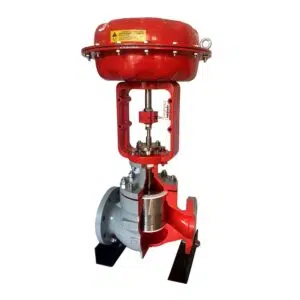
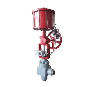
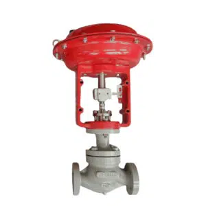
During the selection process, we often see valve failure position, actuator failure position, or other failure requirements in the engineering data sheet. There are many different ways to express them, and we need to pay extra attention to what these terms represent because different designs contain completely different accessory configurations and layouts. For example, an actuator failure position requires an actuator that can achieve various control requirements, but cannot be designed in isolation and must match the processing logic of the system, otherwise, valve action will be incorrect.
Typical 6 Mode of Control Valve Fail Position
Typically in industrial processes, the following 6 modes of fault location are required for control valves.
1. Fail Open(FO)
FO/FC Mode Sheet
| Valve Body | Valve Actuator | Valve Action | Failure Mode |
|---|---|---|---|
| Direct | Direct | Air to Close | Fail Open |
| Reverse | Reverse | Air to Close | Fail Open |
| Reverse | Direct | Air to Open | Fail Closed |
| Direct | Reverse | Air to Open | Fail Closed |
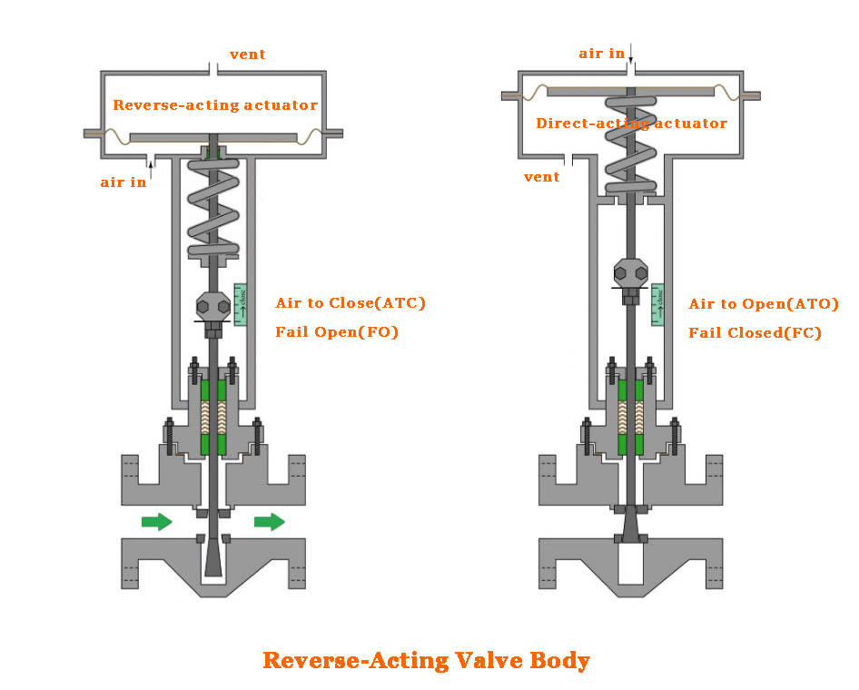
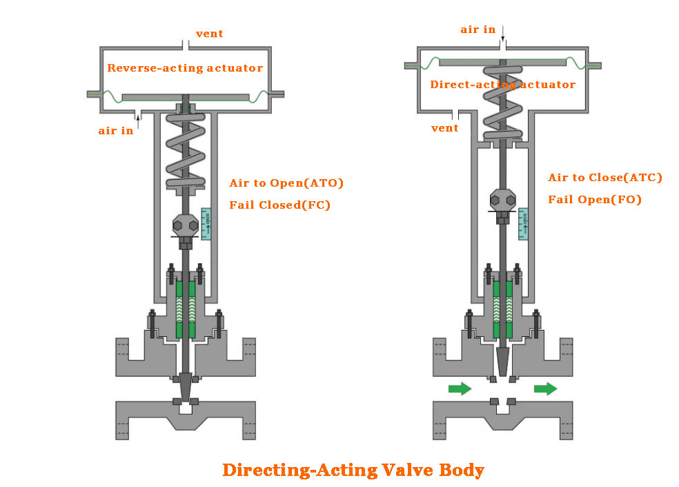
“Fail open(FO)” means air to close, and the control valve is normally at an open position, only when lost air supply, spring return, and pneumatic actuator to open the valve. When air to a pneumatic actuator, the driving to close the valve. Learn from the FO/FC mode sheet, we can know FO is built by combining both reverse acting body and actuator, or a direct-acting valve body and actuator.
2. Fail Closed(FC)
“Fail closed(FC)” means air to open, and the control valve is normally at a close position, only when lost air supply, spring return, and pneumatic actuator to close the valve. When air to a pneumatic actuator, the driving to open the valve. Learn from the FO/FC mode sheet, we can know FC is built by combining a direct-acting valve body and a reverse-acting actuator or reverse acting valve body and a direct-acting actuator.
3. Fail Locked(FL)
There are many applications of industrial control valves that demand the valve to remain at its last set position as a fault condition. This is often referred to as “Fail Last Position”, “Frozen Fault”, “Fail Locked”, or “Fault in Place”. These terms are interchangeable, but to avoid conflict with FL/DC or FL/DO expressions, we mostly use Fail Locked to express that the valve is in the frozen position at the time of failure, i.e., the valve is locked in the last position.
“Fail locked” means when the control valve loses power, the valve stem stays in the last position AND it must be secured in its last position.
When a control valve is used in integral with a positioner as a complete unit, we need to understand that there are two separate failure modes of the positioner.
a. Loss of Signal
Loss of signal means that the signal from the control system providing the set point is interrupted, i.e. the positioner cannot receive the signal source from the central control system, such as 4-20mA, 3-15PSI analog signal.
This is accomplished by using positioners configured with an I/P module that is specifically designed to maintain air pressure in the actuator when the signal voltage falls below the minimum required to operate the I/P. This can be found in the range of 9 to 12 VDC. When the signal is lost, the valve will not drift and will be held at or near the set point. The positioner will resume normal operation when the signal is back to normal.
A fail-freeze positioner or I/P cannot be converted from fail-freeze to fail-safe and vice versa. So we need to purchase the correct positioner for the existing application.
b. Loss of Air Supply
Loss of air supply means that the instrument air supply that powers the pneumatic actuator is interrupted, i.e. the pneumatic actuator has no compressed air to drive it to act.
The above two modes must be considered independent conditions. For Failure locked, we must completely understand which failure mode is required by the end user, Is required to fail locked for loss of signal or loss of air supply of valve positioner? or both? Different requirements require different positioners or other accessory designs to work with.
This is a failure condition that is misunderstood by many engineers. It is generally assumed that this can be achieved using a double-acting actuator. While this may apply to open/close control valves, control valves using positioners operate differently. We can analyze this based on the different ways of air loss.
Sudden air loss
A sudden failure of air pressure because the instrument’s airline breaks close to the control valve and the air is rapidly expelled from the positioner/actuator combination.
In this failure mode, the valve may stay at or near the setpoint. The process forces, the type of valve and actuator, and the rate of air loss will greatly affect the actual valve position after the signal is lost. Under these conditions, the valve position is likely to drift.
Slow air loss
Slowly falling air pressure, possibly due to a tripped compressor, will cause the valve to drift because the air pressure is slowly dropping and the actuator does not have the strength to hold the valve in place. The pressures on both sides of the actuator are no longer balanced and the valve will be forced to close because the positioner cannot maintain pressure balance. In this case, the valve will absolutely drift.
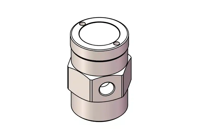
The only way to reliably provide FAIL LAST in the event of loss of air supply is to use an air lock-up valve between the positioner and the actuator to accomplish this. This valve has a sensing port that is connected to the instrument air supply, not far from the valve. There is also an adjustable set point. By adjusting the set point to approximately 10% below the supply air pressure, the lockout valve will shift to hold air in the actuator when the supply air pressure falls below the set point. With the valve locked, the valve will not drift.
When air pressure is restored, the locked valve will automatically shift to restore the air supply to the actuator. No operator intervention is required.
4. Fail Indeterminate
When the signal is lost or power or air is lost, the PID design has not yet determined the position of the valve failure.
5. Fail Last/Drift Open(FL/DO)
“Fail last” means when a control valve lost power, the valve stem stays in the last position.
In the case of “fail last”(fail last position), the force of the flowing eventually pushes the plug of the valve into the fully open position or the fully closed position. So, for FL (Fail Last Position) we need to mention the final position of the control valve stem and plug, indicating the position of the plug after it has been “drifted” by the force of the flowing. FL/DO means fail last and drift open.
6. Fail Last/Drift Closed(FL/DC)
FL/DC means fail last and drift close, and it requests a control valve with”fail last position” as its fail-safe condition.
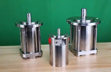
This design usually uses a double-acting with spring-loaded cylinder/piston pneumatic actuator. You may ask why not use a single-acting pneumatic actuator with a lock-up valve to achieve it? Because the single-acting actuator is not a closed-loop circuit, the spring return will directly discharge the air source to the atmosphere, and keep the valve in the last position completely relying on the function of the holding valve to achieve the locking of the air source, the holding valve has a certain time limit, can not always keep the amount of air source does not leak, so it can not guarantee that the valve has been in the last fault position.
The double acting is a closed loop circuit, also with a spring inside, and the control is driven by the air source, the spring only plays a secondary role and only works in case of failure. The important thing is that the double-acting FL/DC or FL/DO design provides a greater driving force during spring return, and the large thrust speeds up the valve action, thus reducing the travel time.
We typically can have this safety position design requirement on control valves in nuclear power plants, which require not only a smaller actuator but also a certain level of seismic resistance. The cost of accessories for this design requirement is relatively high, and the circuit design is also relatively more complex.
How to Select the Proper Control Valve Failure Mode
Above we have learned the main 6 failure modes of control valves, and we all know that excellent safety engineering requires that the risk factors of the process determine the appropriate valve failure mode, not the conventions or habits of the control system.
For example, air to open control valves are generally closed in their normal state, which means they are safer to use a valve that “fail close” than use a valve that “fail open” in this process. If the process is safer using a “fail open” valve, we need to select the air to close (FO) control valve.
So in the select control valve failure mode, we need to combine the basis of all instrumentation actions in the critical control loop, then determine the safest failure mode for the process.
Selecting or configuring the corresponding instrumentation actions makes the control valve continuously move to the safest position.
Case Study-Automatic Cooling System for Generation Engine
For example, take this case study of an automatic cooling system for a large power generation engine.
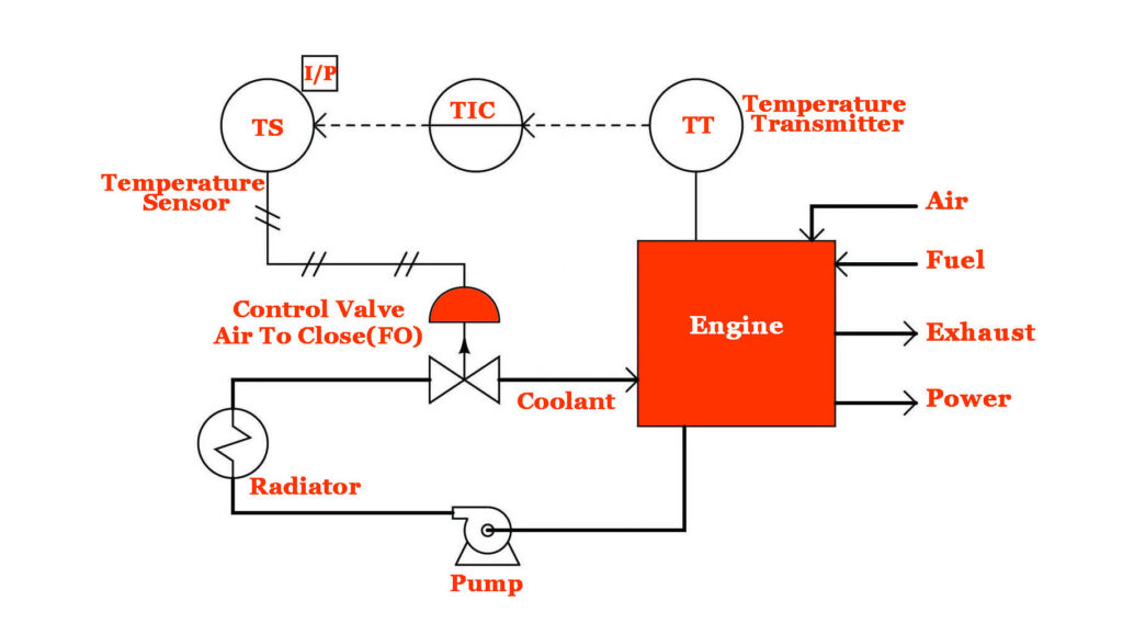
From the design engineering drawing, we can know that a closed valve is more harmful to the engine than an open valve. This is because if the valve is closed, the engine will definitely overheat due to a lack of cooling.
If the fault is open, the engine is simply cooler than designed, and the only negative consequence is a decrease in efficiency. With this in mind, the only reasonable choice for a control valve is a fault-open (air to close) control valve.
However, throughout the system, we need to consider not only the fault design of the control valve, but also need to observe the actions of other instruments, and in this system, we need to consider how to combine temperature transmitters, controllers, and I/P sensors for maximum effectiveness.
In either case, we first need to ensure that the valve is wide open in the fail-safe position, regardless of the failure of the gas source or the occurrence of an input signal failure.
The role of the I/P sensor is to convert the 4-20 mA current signal into the corresponding air pressure that the valve actuator can use.
Since we know that the valve’s failure mode is based on the loss of actuation air pressure, we want the I/P to be configured in such a way that it outputs a minimum pressure in the event of an electrical signal failure in its 4-20 mA input signal wiring.
The result of either a wiring short or an open circuit fault is 0 mA at the I/P’s input terminals. Therefore, the I/P sensor should be configured so that the 4 to 20 mA input signal produces an output pressure of 3 to 15 PSI, respectively, i.e., the minimum input current produces the minimum output pressure.
The next instrument in the cycle is the controller. Here, we expect the most likely input signal failure to result in a minimum output signal, so the valve will (again) default to the “fail-safe” position.
Therefore, we should configure the controller to act directly, as we did with the I/P sensor (i.e., a broken wire or lose connection in the input circuit results in a reduced PV signal and a reduced output signal).
Finally, we come to the last instrument in the control loop: the temperature transmitter. As with most instruments, we have the option of configuring it for direct or reverse action. Direct action means a hotter engine = more mA output, while reverse means a hotter engine = less mA output, so how do we choose?
Here, our choice needs to be such that the overall effect of the control system is negative feedback. In other words, we need to configure the transmitter so that a hotter engine causes an increase in coolant flow (the control valve opens wider).
Since we know that the rest of the system has been designed so that the minimum signal anywhere tends to drive the valve to its fail-safe mode (wide open), we have to choose an emitter that acts in reverse, so that a hotter engine causes the milliamp signal from the emitter to decrease.
If the transmitter has a switch for sensor “burn-in” mode, we should flip this switch to the low scale burn-in position, so a burned-in sensor will result in a 4 mA output (the low end of the 4-20 mA scale), which drives the valve into its safest (wide open) position.
Such a configuration – air to close control valve and reverse acting transmitter – may seem odd and counterintuitive, but it is the safest design for this engine cooling system.
We arrived at this “odd” instrumentation configuration by first selecting the safest control valve failure mode and then selecting the instrumentation action in such a way that the most likely signal path failure anywhere in the system would result in the same, consistent valve response.
It goes without saying, of course, that providing accurate documentation in the form of a ring diagram with a clear indication of instrumentation actions is an absolutely essential part of the overall system.
If the safety of a control system depends on the use of any “non-standard” instrument configurations, then these configurations had better be documented so that those who maintain the system in the future will know what to do!
Another important detail of this system is to configure the controller so that the operator’s display of the output signal is still recorded in an intuitive manner: 0% represents a closed control valve, while 100% still represents a fully open valve.
Since the valve is air to close (signal-close from the controller’s point of view), this means that the controller should be configured to indicate the reverse on the output display, so that a 4 mA output (a wide open valve) reads as 100% open, while a 20 mA output (a fully closed valve) reads as 0%.
While this may be confusing to the technician who services the controller, more importantly, it makes intuitive sense to what the operator who uses the controller does every day.
In Summary
The design in industrial process control is constantly being upgraded, and the control valves and instrumentation systems need to be upgraded to match the automation iteration. THINKTANK, as a reliable Taiwan control valve manufacturer, hope to share more expertise with our customers, if you have any doubts, please just feel free to contact us.
