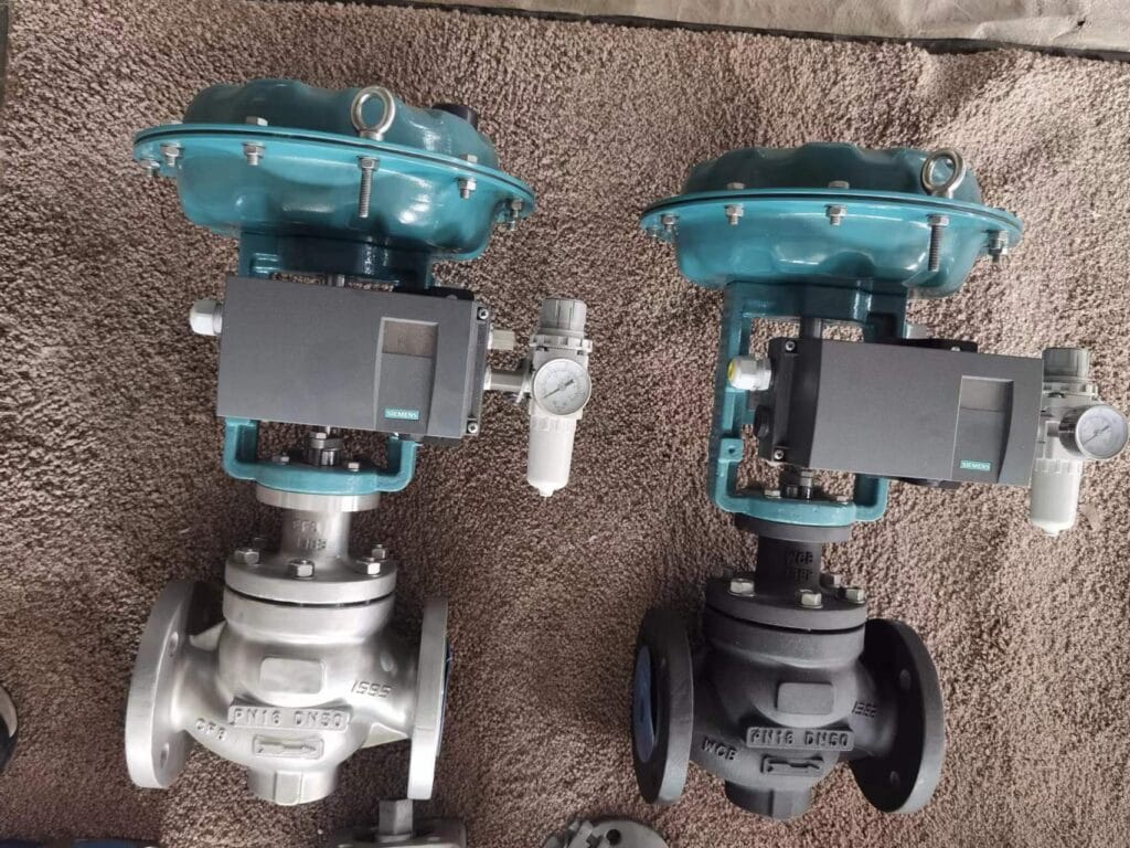
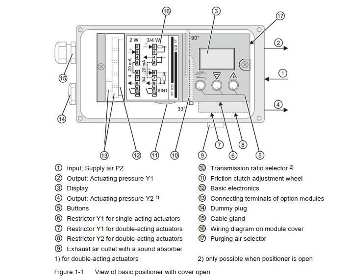
SIPART PS2 is a widely used positioner for sliding and rotary actuators in the process industry. It has a particularly flexible stroke range, intelligent diagnostics, and available HART, PROFIBUS PA communication, or FF communication. Siemens intelligent valve positioner is a good choice for control valves, and we always put this brand as our first option.
Since many customers meet problems with the positioner on site that cannot be solved, we list the common failures in this article to provide solutions for field engineers.
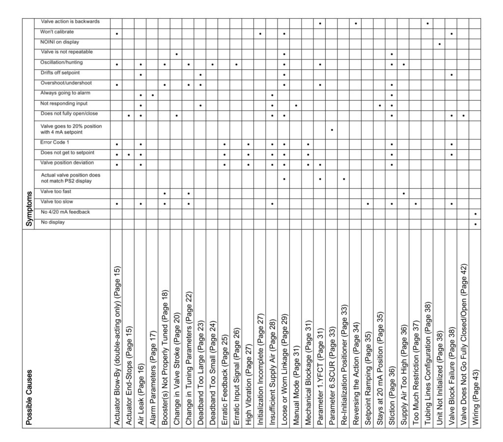
31 Troubleshooting Guide For Siemens PS2 Positioner
1 Pneumatic Actuator Blow-By (double-acting only)
Symptoms
- Valve action is too slow
- Valve won’t calibrate
- Oscillation/hunting
- Overshoot/undershoot
- Error code 1
- Does not get to setpoint
- Valve position deviation
This problem is only found in pneumatic double-acting actuators that are utilizing both Y1 and Y2 output ports.
- One output port adds air pressure while the other exhausts air pressure
- This creates the necessary differential pressure in the actuator to move the valve.
- The two air chambers in the actuator must be isolated from each other; otherwise, the differential pressure cannot increase.
- The actuator has an internal leak and needs to be repaired for blew issues.
a. Air is continuously blown out of the exhaust port when trying to move the valve to a new position.
b. When attempting to move the valve to a new position, the two output pressure gauges, Y1 and Y2, have relatively equal pressure values.
2 Actuator End Stops
Symptoms
- Does no fully close/open
- Does not get to setpoint
The actuator end stop is operable and must be set properly for each valve application. If not set correctly, the actuator will allow the valve to enter the seat excessively, or over-rotate the valve in the open position. This can damage the valve and result in bad process performance.
To identify improper end-stop settings:
● Review actuator/valve manual and determine proper end-stops settings for the valve.
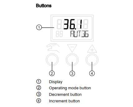
● Put PS2 in manual mode:
From Auto press the Operating mode button ![]() once.
once.
– Use the Increment button ![]() and/or Decrement button
and/or Decrement button ![]() to change the valve position
to change the valve position
● Using the Increment button ![]() and/or Decrement buttons
and/or Decrement buttons ![]() move the valve to both end-stop positions and determine if
move the valve to both end-stop positions and determine if
a valve is seating properly.
● If necessary make adjustments to actuator end-stops, refer to the actuator’s service manual for details.
● Re-initialize PS2
3 Air Leak
Symptoms
- Valve action is too slow
- Oscillation/hunting
- Drifts off setpoint
- Always going to alarm
- Not responding input
- Does not fully close/open
- Error code 1
- Does not get to setpoint
- Valve position deviation
Note: For firmware 5.00.00 or greater only: Verify parameter “PNEUM” is set correctly:
• “Std” = Standard Valve Block or
• “FIP” = Fail In Place Valve Block (“F10” at the end of the model code indicates FIP option.)
Perform a leak test. Any number greater than 1.0 % will need to be corrected to prevent premature wear of the pneumatic valve block.
● From Manual or “noini” mode, drive the valve to a mid-stroke position using the Increment button and/or Decrement buttons.
● Press and hold all three buttons down for at least 2 seconds.
– PS2 will now be in Diagnostic mode, with a diagnostic number in the lower left-hand corner of the display.
● Press the operating mode button to advance through the diagnostic menu.
● Go to diagnostic: “LEAK”.Press and hold the increment button for at least 5 seconds.
– Display will flash between “test” and actual position.
– After one minute, the screen will display the leak rate in percent of travel from original positon.
● To return to Automatic mode, press and hold the operating mode button for 5 seconds.
– The unit will now be in Manual mode.
Press the Operating mode button one time to return to Automatic mode.
● If the leak is detected, check pneumatic fittings, air lines, and actuator.
– Use some form of leak detection or soap and water around the pneumatic connections taking care not to wet the internals of the unit.
– Identify leak and use appropriate method(s) for leak correction.
4 Alarm Parameters
Symptoms
- Always going to alarm
If the unit is always going into alarm, verify configuration settings.
● Parameter “AFCT” (Default is OFF)
– From AUT or MAN mode, press ![]() button for 5 seconds. Now observe the number in the lower left-hand corner.
button for 5 seconds. Now observe the number in the lower left-hand corner.
– Continue to press the ![]() button until Parameter “AFCT” is reached.
button until Parameter “AFCT” is reached.
– This parameter should be set to “OFF”.
Use ![]() and/or
and/or ![]() to change option.
to change option.
● Parameters ” TIM” & ” LIM”
Note: These parameters should never be set to zero.
5 Booster Not Properly Tuned
Symptoms
- Valve action is too slow
- Oscillation/hunting
- Overshoot/undershoot
- Valve action is too fast
The pneumatic volume booster should always be equipped with a bypass needle valve. This needle valve may be external or integral to the booster housing. Adjustment of the needle valve is necessary to achieve proper valve response.
- If PS2 is in Auto and currently operating the valve:
– Rotate the needle valve counter-clockwise to slowdown response and reduce overshoots.
– Rotate the needle valve clockwise to increase valve response
– Re-initialize PS2 after any needle valve adjustments; see Initialization Procedure (Page 50)(see Appendix).
A volume booster must be setup BEFORE initializing a valve positioner. The P-manual mode (“NOINI” flashing), see display example below, can be used to perform this setup.

The P-manual mode will appear once proper electrical power is applied to a new PS2 valve positioner.
If PS2 is currently initialized, activate “NOINI” mode:
– Press and hold ![]() button to enter configuration mode
button to enter configuration mode
– Configuration parameter number appears in lower left corner of display.
– Use ![]() button to reach parameter: “4 INITA”.Press and hold
button to reach parameter: “4 INITA”.Press and hold ![]() button until “no”
button until “no”
appears on top of display.
– Press and hold ![]() button to exit configuration mode
button to exit configuration mode
– Display will be similar to the following (numerical value will vary).
Once all pneumatic connections are made, and the appropriate supply pressure is applied, moving the valve assembly throughout the entire valve stroke can be accomplished using the ![]() and/or
and/or ![]() button/s.
button/s.
– Pressing one button delivers air slowly to the actuator.
– Pressing and holding one button and then pressing and holding the other button will deliver air quickly to the actuator.
– To move valve assembly in the opposite direction, reverse the two push button sequence.
If the valve assembly does not move, it may be possible that the valve assembly is at the actuator end-stop position. Therefore, alternate push button sequence to deliver air in the opposite direction.
– Using ![]() and
and ![]() buttons, move valve assembly to each end-stop position.
buttons, move valve assembly to each end-stop position.
Since the numerical value on the display is an un-calibrated value, use a mechanical indicator on valve assembly to determine the actual valve position.
– Move valve assembly to a mid-travel position and release pushbuttons.
Once push buttons are released valve assembly should immediately stop.
If valve assembly continues to move, adjust needle valve/s a quarter-turn counterclockwise.
– Repeat the above procedure until valve assembly stops when push buttons are released at any travel position.
If this cannot be accomplished, check for air leaks and/or replace volume boosters.
6 Change in Valve Travel
Symptoms
- Valve is not repeatable
- Does not fully close/open
Process Material Build-up
After the valve has been in operation for a long time, process material may build up on the valve and seat, which will prevent the valve from closing completely and cause the media to leak through the seat. In addition, process material buildup can also prevent the valve from opening completely.
To identify this possible, please step by step to check it.
- Put PS2 valve positioner in Manual mode- from Auto, press
 button once.
 - While pressing and holding
 button, press and hold
  button. This will move the valveto an end-stop position. To move valve in opposite direction, reverse push button sequence; while pressing and holding button, press and hold.
 - Use this two-push button method to drive the valve fully open and fully closed.
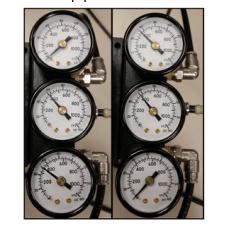
- Utilize pressure gauges to determine if PS2 is outputting full supply pressure and exhausting all output pressure.
-For single-acting (one air pipeline to the actuator)
One end-stop position should show full supply pressure. The other end-stop position will show zero pressure.
-For double-acting (two air pipelines to the actuator)
One end-stop position should show full supply pressure, while the other gauge should show zero pressure. Output pressures will be reversed when driving the valve to other end-stop positions, see the following example of double-acting pressure gauges at each end-stop position.
- If PS2 can output full supply and exhaust in both directions, then something else is preventing the actuator from fully closing or opening.
- Verify supply pressure is properly set.
- If a valve is still not able to fully close or open, then check the actuator/valve for:
-Mechanical binding
-Valve seat wear
Valve Seat Wear
Valve and valve seat wear can cause over-travel and process leaks.
To Identify this:
- Put PS2 in Manual mode- from Auto, press button once.
- While pressing and holding button, press and hold button. This will move the valve to an end-stop position. To move valve in opposite direction, reverse push button sequence; while pressing and holding button, press and hold .
- Use this two-push button method to drive valve fully open and fully closed.
- Utilize pressure gauges to determine if PS2 is outputting full supply pressure and exhausting all output pressure.
-For single-acting (one air pipeline to the actuator)
One end-stop position should show full supply pressure. The other end-stop position will show zero pressure.
-For double-acting (two air pipelines to the actuator)
One end-stop position should show full supply pressure, while the other gauge should show zero pressure. Output pressures will be reversed when driving the valve to another end-stop position, see the following example of double-acting pressure gauges at each end-stop position.

- If PS2 can output full supply and exhaust in both directions, then something else is preventing the actuator from fully sealing to the valve seat.
- Verify supply pressure is properly set.
- If the process is still leaking through the valve, check the actuator/valve for:
-Mechanical binding
-Valve seat wear
7 Change in Tuning Parameters
Symptoms
- Valve action is too slow
- Oscillation/hunting
- Overshoot/undershoot
- Valve action is too fast
The SIPART PS2 uses a control method called “pulse width modulation”. This is a true digital control method, where piezo valves, similar to very small solenoid valves, are used to control loading and exhausting air, to and from the positioner. As such, the tuning parameters listed below are based upon this control method.
Adjustable Tuning Parameters Descriptions:
- [IMPUP] & [IMPDN]: Impulse Length UP and DOWN
-These tuning parameters are similar to gain. They represent the minimum time the piezo valves will cycle; units are in milliseconds- ms. For example; if the value is 10 ms, the fastest the piezo valves will cycle is 10 ms, not any faster. Therefore, an increase in these values will increase the gain response. The range is 2.0 to 160 ms.
- [SSUP] & [SSDN]: Short Step Zone
These tuning parameters are similar to integral action. Essentially there are two actions of the piezo valves- long pulses and quick/short pulses. The values are in percent of total stroke. When the position of the valve is within this Short Step Zone of the setpoint value, the positioner will begin the short pulses of the piezo valves. For example, if the current short step zone is 10 % and the positioner is given a step change from 0 to 50 %, the piezo valves are held wide open (long pulse) until the valve gets to within 10 % of the setpoint. Therefore, once the valve is at 40 %, the piezo valves will produce short/quick pulses, to prevent overshoots. The smaller the value, the faster the response.
- [PRUP] & [PRDN]: Prediction Up and Down
-These tuning parameters are similar to derivatives. This predicts the movement of the valve. The smaller the number, the less prediction is used, thus faster response. The range is 1 to 40.
How to customize tuning parameters:
- Enter Diagnostic Mode:
-When the device is in Auto mode, press and hold all three buttons down at the same time:![]()
![]()
![]() .
.
-Diagnostic name is shown in the lower right of the display.
Edit Tuning Value:
-Go to the desired diagnostic parameter by pressing and releasing button. This will advance through the diagnostic menu.
To go backward in the menu: While pressing and holding ![]() button, press and release
button, press and release ![]() button.
button.
-Once at the desired tuning parameter: Press and hold ![]() button until the number starts to change.
button until the number starts to change.
-Use ![]() and/or
and/or ![]() buttons to achieve desired tuning value.
buttons to achieve desired tuning value.
- Exit Diagnostic Mode:
-Press and hold ![]() button until display changes.
button until display changes.
-If the unit is in Manual mode, press ![]() button once to go to Auto mode.
button once to go to Auto mode.
8 Deadband Too Large
Symptoms
- Drifts off setpoint
- Overshoot/undershoot
- Not responding input
The deadband of the PS2 is the area around setpoint when the PS2 stops working to get closer to setpoint. For example, if the deadband value is 0.5 %, and the setpoint is 70 %, the PS2 will work the piezo valves to get within the following position range: 69.5 to 70.5 %. If the deadband is too large, the PS2 may not achieve the desired position.
There are two settings for the PS2 Deadband: Auto or a fixed numerical value.
- When configuration parameter “DEBA” = “Auto”, the deadband value is dynamic and changes per process conditions.
- When configuration parameter “DEBA” is a fixed numerical value, the PS2 will always move the valve to get within this range of the setpoint.
- The current deadband value can be viewed in diagnostic mode:
-While in automatic mode, press all three buttons down at the same time for 5 seconds.
-Press ![]() button until diagnostic parameter “DBUP” or “DBDN” is shown.
button until diagnostic parameter “DBUP” or “DBDN” is shown.
-These diagnostic parameters show the current deadband value for up and down valve
directions.
- If deadband value is too large for the application, the PS2 is compensating to prevent valve oscillations. These valve oscillations could be:
-Too many steps change from the process controller. This is a process control loop issue. Discuss the issue with the operator and/or plant process engineer.
Change Deadband Setting:
- From AUT or MAN mode, press button for 5 seconds. Now observe the parameter name in the lower right corner.
- Continue to press the button until “DEBA” parameter is reached.
- Use and/or buttons to decrease deadband value.
- To return to Automatic mode, press and hold the button for 5 seconds.
- The unit will now be in Manual mode.
- Press the button one time to return to Automatic mode.
9 Deadband Too Small
Symptoms
- Oscillation/hunting
The deadband of the PS2 is the area around the setpoint when the PS2 stops working to get closer to setpoint. For example, if the deadband value is 0.1 %, and the setpoint is 70 %, the PS2 will work the piezo valves to get within the following position range: 69.9 % to 70.1 %. Thus, the PS2 will continuously work to get within this deadband range. However, if the mechanics of the actuator and/or valve cannot achieve this precise position, the PS2 will continuously hunt or oscillate around the setpoint position.
There are two settings for the PS2 deadband: “Auto” or a fixed numerical value
- When configuration parameter “DEBA” = “Auto”, the deadband value is dynamic and changes per the process conditions. In other words, the deadband value changes if stiction or oscillation is detected. For example, the deadband value will increase when mechanical issues are detected. Additionally, the PS2 will periodically decrease the deadband value to try and achieve precise valve positioning. The deadband value changes in 0.1 % increments.
- Thus, only a fixed deadband value can be too small.
- Too small a deadband can cause valve oscillation and indicate.
Change Deadband Setting:
- From AUT or MAN mode, press button for 5 seconds. Now observe the parameter name in the lower right corner.
- Continue to press the button until “DEBA” parameter is reached.
- Use and/or buttons to decrease deadband value or change to “Auto”.
- To return to Automatic mode, press and hold the button for 5 seconds.
- The unit will now be in Manual mode.
- Press the button one time to return to Automatic mode.
10 Erratic Feedback
Symptoms
- Error code 1
- Does not get to setpoint
- Valve position deviation
The PS2 is providing a false and jumpy feedback signal, but the actual valve position is not moving.
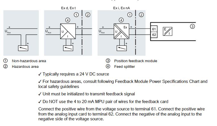
First, rule out field wiring and power supply:
Does the large number on the local display represent the jumpy and false signal read on the 4-20 mA feedback?
If No:
- Use an independent power source and current meter to isolate the field wiring by powering up the feedback card locally.
-24 V DC positive connected to terminal 61.
-Put meter in current mode and connect positive to terminal 62.
-Connect the wire of the current meter to 24 V DC negative, according to the Wiring below.

- If erratic feedback is gone, then the issue is with field wiring or the original power source.
If Yes:
- Put PS2 in Manual mode: from Auto, press button.
- Move valve with or buttons.
- If a false feedback signal is corrected by moving the valve, consider Non-Contacting technology.
- If false feedback is still present when moving the valve, verify:
- Slide bar is in proper location:
First, unlock slide bar: see Transmission Ratio/Slide (Page 49).
Move slide bar back and forth twice, then move slide bar to proper setup position (see following):
– For rotary, slide bar = 90°.
– For linear valves with travel at 25 mm (1.0 inch) or less; slide bar = 33°.
– For linear valves with travel at 25 mm (1.0 inch) or more; slide bar = 90°
● Reinitialize PS2. See Initialization Procedure (Page 50).
11 Erratic Input Signal
Symptoms
- Oscillation/hunting
There are two ways to identify if the input signal is causing the valve behavior. One is placing a current meter in series of the 4 to 20 mA loop. The other is using the PS2’s display as a current meter. This is found in diagnostic parameter “mA”.
- While the positioner is exhibiting the problem, verify unit is in Automatic mode.
- Press and hold all three buttons for at least 5 seconds.
-The diagnostic parameter name can be found in the lower right corner.
- Press the to advance through the menu.
- Go to Diagnostic parameter “mA”.
– Observe the movement of the actuator/valve and compare it to what is displayed on the PS2, or current meter. If the display is changing with the valve assembly, then the input signal is the cause. An investigation of the control system/loop tuning is suggested.
12 High Vibration
Symptoms
- Error code 1
- Does not get to setpoint
- Valve position deviation
Too much vibration can cause erroneous feedback and damage the positioner. The SIPART PS2 vibration specifications are:
- Harmonic oscillations (sine-wave) according to EN 60068-2-6/10.2008
- Bumping (half-sine) according to EN 60068-2-27/02.2010
- Noise (digitally controlled) according to EN 60068-2-64/04.2009
- Recommended continuous duty range of the complete fitting
- If excessive vibration cannot be avoided, consider Non-Contacting technology. Contact Siemens technical support for assistance: 1-800-333-7421.
13 Initialization Incomplete
Symptoms
- Won’t calibrate
| Fault Profile (symptoms) | Possible Cause(s) | Corrective Measures |
| Positioner remains in”RUN 1″ | • Waiting time of 1 minute not accomplished. • Loose or Worn Linkage (Page 29) • Supply air not connected or Insufficient Supply Air (Page 28) • Valve Block Failure (Page 38) | • A waiting time of 2 minutes is essential. Start initialization from a mid-stroke position. • See Loose or Worn Linkage(Page 29) • See Insufficient Supply Air(Page 28) |
| Positioner remains in “RUN 2” | • Transmission ratio selector and parameter “2. YAGL” is not set correctly and/or real stroke does not match. • Incorrectly set stroke on the lever. • Valve Block issue, see Valve Block Failure (Page 38) | • Initialization Procedure(Page 50) • See “Possible Messages” table of Leaflet. • If “Tolerance Band Down Violated” message, adjust slip-clutch as instructed in leaflet |
| Fault Profile (symptoms) | Possible Cause(s) | Corrective Measures |
| Positioner remains in “RUN 3” | • Actuator travel time is too high. • Air Leak (Page 16) • Non-active zone is in the valve stroke*. Non-active zone is in the valve stroke*, see Valve Block Failure (Page 38) | • Open the restrictor completely and/or set the supply air to the highest permissible value see Insufficient Supply Air (Page 28) • See Air Leak (Page 16) • See star notation below. • Use a booster if faster stroke times are desired. |
| Positioner remains in “RUN 4” | • Air Leak (Page 16) • Booster(s) Not Properly Tuned(Page 18) • Loose or Worn Linkage (Page 29) | • See Air Leak (Page 16) • See Booster(s) Not Properly Tuned (Page 18) • See Loose or Worn Linkage (Page 29) |
| The positioner remains in “RUN5”, but does not go up to “FINISH” (waiting time> 7 min). | • Loose or Worn Linkage (Page 29) • Booster(s) Not Properly Tuned (Page 18) • Air Leak (Page 16) | • Part-turn actuator: verify coupling set screw is secure. • Linear actuator: verify lever arm is secure to input shaft. • Correct any slack between the actuator and valve. • Loose or Worn Linkage (Page 29) |
14 Insufficient Supply Air
Symptoms
- Valve action is too slow
- Always going to alarm
- Not responding input
- Does not fully close/open
- Error code 1
- Does not get to setpoint
- Valva position deviation
Maximum air pressure ratings are displayed on the actuator’s nameplate/stamp. Using too little air pressure will slow down the stroke times of the valve assembly. The PS2 positioner can handle up to 100 psi as long as the recommended actuator pressure is not exceeded.
- Adjust supply pressure according to the application.
- If pressure adjustments are made, run initialization. See Initialization Procedure(Page 50)
15 Loose or Worn Linkage
Symptoms
- Oscillation/hunting
- Won’t calibrate
- Valve is not repeatable
- Drifts off setpoint
- Overshoot/undershoot
- Doest not fully close/open
- Error code 1
- Does not get to setpoint
- Valve position deviation
- Valve action is too slow
A valve positioner’s performance is directly dependent upon its mechanical connection to the actuator. For example, if the mechanical coupling is loose or worn on the positioner’s input shaft, valve performance will suffer.
- Identify loose or worn linkage as follows:
A loose input shaft can quickly be determined by moving the PS2’s slip clutch. See item #6 of Transmission Ratio/Slide Bar (Page 49). The slip clutch should not rotate without clicking. The flameproof enclosure should rotate easily.
– Put PS2 in Manual mode from Auto press![]() button.
button.
Note: NOINI mode can also be used.
– Using the ![]() and/or
and/or ![]() buttons, move the valve back and forth in both directions.
buttons, move the valve back and forth in both directions.
– While the valve is moving back and forth inspect the movements of:
○ For Rotary: Actuator shaft, Positioner coupling and Positioner input shaft.
○ For Linear: Actuator shaft, Actuator stem coupling, Feedback pin, Feedback arm, and Positioner input shaft.
– All of these components must move in unison- all together.
○ Several back and forth movements will be necessary to identify the loose component.
16 Manual Mode
Symptoms
- Not responding input
When bottom section of display shows: “MANxx” (xx = input signal), the unit is in Manual
mode. In Manual mode, the unit ignores setpoint command signal. It is possible to use the![]() and/or
and/or ![]() buttons to manually drive the actuator.
buttons to manually drive the actuator.
● To exit manual mode and allow control using a setpoint, press ![]() button one time.
button one time.
– Unit will display: “AUTxx” (xx = input signal), in the lower right-hand corner when in
Automatic mode.
17 Mechanical Blockage
Symptoms
- Error code 1
- Does not get to setpoint
- Valve position deviation
While position deviation exists, determine which output pressure gauge is used to move the valve and eliminate the current deviation.
● If the output pressure is equal to supply pressure, then:
– Issue is not the PS2, check for mechanical blockage that is preventing valve movement. This could occur in the actuator and/or valve, refer to the actuator/valve service manual.
● If the output pressure is unable to reach full supply pressure, then:
– Issue is an air leak somewhere in the output; see Air Leak (Page 16).
● If output pressure is unable to exhaust, check the exhaust port for blockage; otherwise, replace the piezo block.
● If PS2 is satisfied with the current position deviation, the deadband could be too large.
18 Parameter 1.YFCT
Symptoms
- Oscillation/hunting
- Valve action is backward
- Overshoot/undershoot
- Valve position deviation
- The actual valve position does not match the PS2 display
The two most common options for parameter 1 are WAY and TURN. “WAY” is for linear actuators which will have feedback arm/linkage connecting the positioner to the actuator.
“TURN” is for rotary actuators which have a direct coupling connecting the positioner to the actuator.
Firmware version 5.00.00 and newer will have a normal and inverted actuator type for all Parameter 1 options. Inverted selections are identified with a minus sign. Normal and inverted refers to the rotation of the PS2’s input shaft when the valve or damper closes.
Use Normal:
- Part-turn actuator closes when the positioner shaft or NCS rotates in the clockwise direction.
- Linear actuator closes when the actuator spindle moves downwards and the positioner shaft or NCS rotates in the anti-clockwise direction.
Use Inverted, indicated with the minus symbol if valve moves in opposite direction as described above.
- Turn/-turn: For a part-turn actuator with a directly mounted positioner.
- WAY/-WAY: For a linear actuator with a carrier pin mounted on the lever.
- FWAY/-FWAY: For a linear actuator with a carrier pin mounted on the actuator spindle.
- LWAY/-LWAY: For an external linear potentiometer on a linear actuator.
- ncSt/-ncSt: For an NCS sensor (6DR4004-.N.10 and -.N.40) on a part-turn actuator, and for an internal NCS module.
- ncSL/-ncSL: For an NCS sensor (6DR4004-.N.20) on a linear actuator for strokes < 14 mm (0.55 inch).
- ncSLL/-ncLL: For an NCS sensor (6DR4004-.N.30) on a linear actuator for strokes >14 mm (0.55 inch) and for an internal NCS module.

19 Parameter 6.SCUR
Symptoms
- Valve goes to 20% position with 4mA setpoint
Default setting is: “4 mA”.
- From AUT or MAN mode, press button for 5 seconds. Now observe the parameter name in the lower right corner.
- Continue to press the button until “SCUR” parameter is reached.
- If it says “0 mA”, press the button to change this to “4 mA”.
- To return to Automatic mode, press and hold the button for 5 seconds.
- The unit will now be in Manual mode.
- Press the button one time to return to Automatic mode.
20 Re-Initialization Positioner
Symptoms
- The actual valve position does not match the PS2 display
21 Reversing the Action
Symptoms
- Valve action is backward
There are two ways to invert the action and display, one requires re-initialization.
No re-initialization procedure
This procedure inverts the physical action and display of the positioner.
- Parameter “SDIR” reverses the physical action
-From AUT or MAN mode, press ![]() button for 5 seconds. Observe parameter name in the lower right corner.
button for 5 seconds. Observe parameter name in the lower right corner.
-Continue to press ![]() button until “SDIR” Parameter is reached.
button until “SDIR” Parameter is reached.
-If “SDIR” Parameter displays “riSE” change to “FALL” or vice versa.
Use ![]() and/or
and/or ![]() buttons to change option.
buttons to change option.
- “YDIR” Parameter reverses the display and feedback signal.
– Continue to press ![]() button until “YDIR” Parameter is reached.
button until “YDIR” Parameter is reached.
– If “YDIR” Parameter displays “riSE” change to “FALL” or vice versa.
Use ![]() and/or
and/or ![]() buttons to change option.
buttons to change option.
– To return to Automatic mode, press and hold ![]() button for 5 seconds. The unit will
button for 5 seconds. The unit will
now be in Manual mode.
– Press![]() button one time to return to Automatic mode.
button one time to return to Automatic mode.
Note: If using the alarm card and/or advance diagnostics, the alarm thresholds values may not match actual valve position. To correct this, use the following procedure to reverse the action.
Re-initialization Procedure (Firmware 5.00.00 or greater)
Firmware number is printed on PS2 nameplate. Also, the display flashes firmware number when exiting configuration mode.
Change Parameter 1 to the inverse functions:
● From AUT or MAN mode, press ![]() button for 5 seconds. Observe number in the lower
button for 5 seconds. Observe number in the lower
left hand corner.
● Continue to press ![]() button until Parameter 1 is reached.
button until Parameter 1 is reached.
● Change parameter 1 value to its inverse. For example change “turn” to “-turn”.
● When Parameter 1 is changed, the unit must be re-initialized.
22 Setpoint Ramping
Symptoms
- Valve action is too slow
The setpoint ramp is only effective in Automatic mode. This parameter changes the positioner’s speed of response. Essentially, this slows down the valve travel times. To achieve the fastest times, these parameters should be set to a value of zero.
● From Manual or Automatic mode press and hold button for 5 seconds to enter configuration menu.
– Pressing the ![]() will advance through the parameters.
will advance through the parameters.
● Go to parameter “TSUP” and “TSDO”.
– Use the ![]() and/or
and/or ![]() button to change the values.
button to change the values.
● To return to Automatic mode, press and hold ![]() button for 5 seconds.
button for 5 seconds.
– The unit will now be in Manual mode.
● Press ![]() button once to return to Automatic mode.
button once to return to Automatic mode.
23 Stays at 20 mA Position
Symptoms
- Not responding input
When PS2 is in automatic or manual mode, the input signal is shown in the lower right corner of the display. This value is in percent and should change with a change in the input signal.
Use PS2 diagnostic number “mA” to convert the display to the current meter.
● From automatic mode or manual mode, press all three buttons down at the same time for
5 seconds.
● Press and release ![]() button and go to diagnostic parameter “mA.”
button and go to diagnostic parameter “mA.”
● The display will show input signal in milliamps.
If milliamp is approximately fixed to 22.0 mA, this indicates the board was or still is
improperly powered.
● To exit Diagnostic mode press and hold ![]() button until display changes.
button until display changes.
For 2-wire loop power, the power supply must be a regulated current source. A current
source regulates current.
Note
A voltage source does not regulate current, the circuit’s resistance does. Therefore if the circuit’s resistance is low, the current can be too high and damage the PS2 board.
- Resolve power issue and replace PS2 circuit board. Board part numbers can be found in PS2 Operating Instructions P/N#: A5E00074631, or contact Siemens.
If milliamp changes with the input signal, check PS2 configuration.
- To restore all PS2 parameters to factory setting:
– From Auto/Manual mode, press and hold button until display changes.
– Press and release button and go to “PRST” parameter.
– Press and hold button until display shows: “OCAY”
● Set configuration parameters as per the application and re-initialize PS2,
24 Stiction
Symptoms
- Valve action is too slow
- Oscillation/hunting
- Valve is not repeatable
- Overshoot/undershoot
- Always going to alarm
- Not responding input
- Does not fully close/open
- Error code 1
- Does not get to setpoint
- Valve position deviation
This term is used to identify the friction that exists in a valve assembly that prevents smooth stem motion. An example is an initial friction that exists when pushing a heavy box across the floor- first, the pushing force must overcome the friction before the box will move.
If stiction is too great in a valve assembly, then the valve is unable to achieve small valve movements, such as 0.1 %.
To identify this symptom:
- Put PS2 in Manual mode- from Auto press button once.
- While using the and/or buttons try to move valve assembly in the smallest movements, for example, 0.2 % movements.
- If the valve assembly cannot achieve these small movements manually, then there is too
- much stiction.
- The way to quantify how much stiction exists is by how little the valve can move. For example, if the smallest movement that can be achieved is 0.8 %, then this is the best the valve assembly can move- in 0.8% increments. Therefore trying to achieve smaller movements is impossible and will result in oscillations.
- Oscillations can be reduced by setting the Deadband value to “Auto”.
25 Supply Air Too High
Symptoms
- Oscillation/hunting
- Valve action is too fast
Maximum air pressure ratings are indicated on the actuator’s nameplate/stamp. Using too much air pressure can inhibit performance and could damage the actuator and/or positioner. The PS2 positioner can handle up to 100 psi as long as the recommended actuator pressure is not exceeded.
● Adjust supply pressure according to the application.
● If adjustments are made, run the initialization process
High supply pressure can cause quick valve responses, and lead to overshoots, oscillations, and incomplete initialization. If high supply pressure is required for application, the minimum travel time may not be met. The PS2 requires at least 1.0 second of travel time for each valve direction. If PS2 has been initialized, travel times can be found in Diagnostic menu:
- From Auto or Manual modes, press all three buttons down for 5 seconds.
- Diagnostic name will be shown in lower right of display.
- Press button until “TUP” and TDOWN” are shown.
If travel times are faster than 1 second, reduce valve travel speed with built-in flow restrictor/s see Device Identification section 1.4, items 6, 7 and 8:
- During RUN 3 of initialization process, the display will flash with valve travel times.
- Press button while times are flashing on display.
- Display will show “NOZZL”. Adjust built-in flow restrictor/s in clockwise direction with appropriate Allen key.
- Press button again and PS2 will fully stroke the valve and update the display with the current travel times.
- If minimum travel times are not met, at least 1 second for both directions, then press button again while display is flashing travel times.
- Adjust built-in flow restrictor/s clockwise to restrict more flow to and from actuator.
- Press button and repeat as necessary. If desired travel times are met, do not push any buttons and PS2 will complete initialization process.
26 Too Much Restriction
Symptoms
- Valve action is too slow
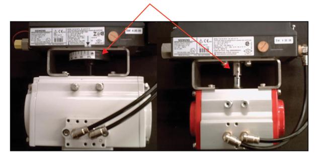
To achieve the fastest possible stroke times, verify the restrictor screws are in their factory position which is all the way open. See photo for the actual position.
- If there are any issues with response/stroke times, then open the restrictor(s) by turning counter-clockwise until the factory position is reached.
If restrictor screws were adjusted, a new initialization needs to be performed.
27 Tubing Lines Configuration
Symptoms
- Valve action is backward
28 Unit Not Initialized
Symptoms
- NOINI on display

29 Valve Block Failure
Symptoms
- Valve action is too slow
- Won’t calibrate
- Drifts off setpoint
- Does not fully close/open
- Error code 1
- Does not get to setpoint
Valve block failure can occur for several reasons. The most common failure is a result of poor air quality, which can include moisture. In addition to an air drying system, it is recommended to install a coalescent filter on the supply line, directly upstream of the positioner. Siemens offers an Air Coalescing Filter, Model 2306, which removes dirt, oil, moisture, and other impurities from the instrument-air supply.
In addition, exceeding the recommended supply pressure will damage the valve block. The maximum pressure rating for the PS2 is: 101 psi (7 bar), see Supply Air Too High (Page 50).
It is recommended to install a regulator on the supply line, upstream from the positioner, and to regulate supply pressure so it does not exceed the maximum pressure rating of the PS2 and the actuator. Siemens offers a filter regulator, Model 91H, which regulates pressure and removes debris.
Valve Block Testing
The following tests will refer to gauges on the supply and output(s) of pneumatic lines. If the PS2 does not have a gauge block, consider temporary gauge installation (inline) for diagnostic purposes. Pipe plugs may also be needed; either ¼ inch NPT or G¼ thread.
Verify pneumatic port thread type before inserting pipe plugs – refer to model code and SIPART PS2 catalog sheet.
Activate NOINI Mode (if not already activated)
Enter configuration mode and go to parameter: “4.INITA”.
– From AUT or MAN mode, press ![]() button for 5 seconds.
button for 5 seconds.
– Parameter number will be displayed in lower left-hand corner.
– Press and release ![]() button and go to parameter “4.INITA”.
button and go to parameter “4.INITA”.
– Once at parameter “4.INITA”, press and hold![]() button until display changes to: “no”.
button until display changes to: “no”.
– Press and hold ![]() button for 5 seconds to exit configuration mode.
button for 5 seconds to exit configuration mode.
– Display should flash “noini” in the lower right.
Use Two-Button Method to Simulate Movement
- While pressing and holding the button, press and hold the button.
- To move the valve assembly in the opposite direction, reverse the two push-button sequences. Use the two-button method and observe pressure changes on each output gauge.
- Single-acting – In one direction the output gauge should reach full supply pressure and hold when the buttons are released. When going in the opposite direction, the output gauge should go to zero psi. While it is going to zero, air pressure should be blowing out of the exhaust port.
- Double-acting – The two output gauges will indicate opposite pressures from each other, when at each end-stop position. While the top gauge is pressurizing the bottom gauge should be exhausting. The gauge that is pressurizing should reach full supply and hold when the buttons are released. The device should only exhaust while the unit is moving. At rest, no air should be blowing out of the exhaust port.
Makrolon Enclosure & Flameproof Enclosure

If PS2 can output full supply pressure and fully exhaust, then something else is preventing actuator from fully closing or opening. Check valve assembly for mechanical blockage and air leaks. Also verify supply is at required pressure for application.
● If possible, drive actuator/valve to a mid-travel position (50 %). Does air pressure hold
when the buttons are released?
– If yes, the valve block/PS2 is working correctly.
– If not, check for leaks and perform the Pipe Plug Test at the end of this section.
● Does the unit exhaust?
– For double-acting, the unit should always exhaust during movement. For single-acting, the unit will only exhaust in one direction.
– If one of the output ports does not exhaust, check exhaust port for blockage.
○ If exhaust port is free from blockage, go to Pipe Plug Test at the end of this section.
– If unit always exhausts, verify parameter “PNEUM” is set correctly.
○ “Std” = Standard Valve Block or “FIP” = Fail in Place Valve Block (“F01” at end of the model code indicates FIP option).
○ If this is set correctly, go to the Pipe Plug Test.
Pipe Plug Test
- Turn off supply air to PS2.
- Slowly remove pneumatic connections from the output port(s) on the positioner.
- Install appropriate thread type pipe plug into each output port(s). The only pneumatic line connected to the PS2 should be supplied. See photo below.

Use the two-button method to pressurize the output chamber.
– Repeat this in both directions.
If PS2 can output full supply and fully exhaust, then something else is preventing the actuator from fully closing or opening. Check valve assembly for mechanical blockage and air leaks.
Also verify supply is at required pressure for application.
● If PS2 does not exhaust pressure from one of the output ports, replace the valve block.
● If the unit does not hold pressure when buttons are released, check for leaks around pipe plug(s), gauge manifold block and PS2 pneumatic connection block (this is a black anodized aluminum block directly against PS2 enclosure).
– If no leaks are found, replace the valve block.
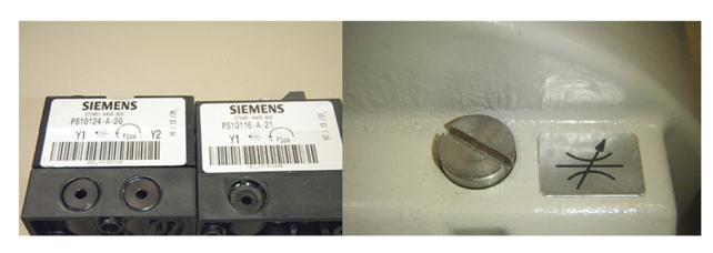
Replacement Part Numbers
Pneumatic single-acting piezo block kit: C73451-A430-D80
Pneumatic double-acting piezo block kit: C73451-A430-D81
Each kit includes a Valve block, O-ring, and Screws.
30 Valve Does Not Go Fully Closed/Open
Symptoms
- Does not fully close/open
From AUT or MAN mode, press ![]() button for 5 seconds.
button for 5 seconds.
– Observer parameter name in the lower left hand corner.
● Continue to press ![]() button until “YCLS” Parameter is reached.
button until “YCLS” Parameter is reached.
– Note: While in configuration mode, the positioner is NOT controlling the valve.
● Use ![]() and
and ![]() buttons to change Parameter values:
buttons to change Parameter values:
– Set Parameter YCLS to “Up do” (Tight Closing Up and Down)
● To exit configuration mode, press and hold ![]() button for 5 seconds.
button for 5 seconds.
– Unit should be in Manual Mode.
● Press and release ![]() button once to enter AUTO mode.
button once to enter AUTO mode.
● Verify the valve assembly goes to the fully open and/or closed position with a 0 or 100%
command signal.
● If not:
– The problem may be the input signal. Use the PS2’s display as a current meter. This is found in the Diagnostic parameter “mA”.
– Verify unit is in Automatic mode.
– Provide a 4 mA input signal.
– Press all three buttons down until display changes.
○ Diagnostic menu will be displayed. The diagnostic name can be found in the lower
right corner.
● Press the ![]() button to advance through the menu.
button to advance through the menu.
– While pressing and holding ![]() button, press the
button, press the ![]() button to go backwards in menu.
button to go backwards in menu.
● Go to option “mA”.
● Observe display and verify if the positioner is actually displaying ≈ 4 mA. If not, then the
input signal is the cause.
● To exit diagnostic mode, press and hold![]() button for 5 seconds.
button for 5 seconds.
31 Wiring
Symptoms
- No display
- No 4-20mA feedback
2-Wire Connection Wiring For Siemens Positioner
2-Wire Connection Wiring of PS2 Positioner
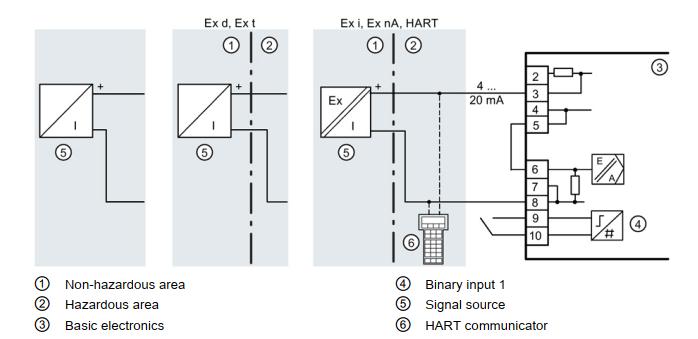
4 to 20 mA Feedback Module Wiring of PS2 positioner

Troubleshooting SIPART PS2 Siemens Digital Positioner For Control Valves
Case 1: Control valve can not be fully closed
Solution:
In the process production, due to plug wear or large differential pressure, the control valve may not be tight shutoff, and it will cause leakage that affects the process operation. You can set parameters 39YCLS, 40YCD, 41YCU, and other items to enable the tight shutdown function, the control valve will be closed as much as possible. In chemical production, process operators often describe that the control valve can’t be closed and there is a large leakage, which affects the operation, we can use this function to meet the needs of the process as much as possible without replacing the control valve.
Case 2: The flow curve of the control valve is not ideal
Solution:
SIPART PS2 valve positioner parameter 12SFCT item, built-in six common flow characteristics of control valves and user-defined flow characteristics, each control valve has its inherent flow characteristics, usually, this parameter of the positioner can follow the inherent flow characteristics of the control valve as long as it is set to Lin. If the flow characteristics of the control valve do not match the process requirements, the overall flow characteristics of the control valve can be changed through the setting of parameter 12SFCT. In short, the flexible setting of parameter 12SFCT can meet the process requirements according to the actual situation.
Case 3: Control valve action direction is not consistent with the requirements
Solution:
This is related to the setting of the two parameters 7SDIR and 38YDIR of the valve positioner. The 7SDIR item is the direction set point, and the setting of the 7SDIR item determines the lifting and lowering of the actuator when the positioner receives the 4~20mA signal.
The 38YDIR item is the travel direction display, which shows the lift of the actuator. By comparing with the actual switching direction of the control valve and the signal output from the control room, the parameter 7SDIR and parameter 38YDIR can be set correctly. when determining the switching direction of the control valve, it is necessary to cooperate with the process personnel, especially for the rotary type control valve, when the indication mark of the actuator is not clear, it is easy to misjudge the switching and cause production accidents, which must be taken seriously.
Case 4: Siemens SIPARTPS2 positioner initialization stops at RUN5 and does not reach Finish (waiting time >5min)
Solution:
The cause of this fault is the installation of the positioner, actuator, and other components. You can check the installation of the positioner, actuator, and feedback part, correct the problem in time, re-assemble it and then initialize it to see if the initialization time can be shortened.
Case 5: Siemens SIPARTPS2 positioner stops at RUN3 during initialization
Solution:
The reason for this fault is that the actuator takes too long to position. We observe whether the actuator switching time can be reduced by opening the restrictor completely or adjusting the pressure PZ (air pressure) to the high allowed value. You can also use a booster to increase the actuator force and shorten the switching time.
Case 6: When Siemens SIPARTPS2 positioner initializes, it stops at RUN2 and cannot proceed
Solution:
Due to the high adaptive capability of the Siemens SIPARTPS2 positioner, it can work with linear and rotary type actuators with different travels. The positioner needs to set the parameters corresponding to the stroke during initialization so that the potentiometer detects the displacement of the actuator and the positioner drives the actuator action according to this displacement signal. If it stops at RUN2 during initialization, it is possible that the parameter setting is not reasonable. You can change the feedback shaft rotation angle in parameter 2YAGL of the valve positioner, changing 33° to 90°, and then initialize it again to see if it is successful. If the rotation angle of the feedback shaft is smaller than the small rotation angle, the initialization will not be successful. The feedback shaft rotation angle can be set as follows: set 33° when the stroke of the linear actuator is less than 20mm. Set 90° when the stroke of the linear actuator is more than 20mm. Set 90° automatically for the rotary type control valve.
In addition, the stroke or angle of the actuator can also be adjusted manually. Manually adjusting the actuator stroke to the start and end positions can complete the step of RUN2. It is not necessary to automatically find the starting point of the actuator during the initialization of the positioner. So when automatic initialization is not possible, manual initialization is selected to enable the control valve to be adjusted.
Case 7: The positioner makes a sound of puffing, and the control valve produces a vibration
Solution:
This is because of the positioner air tubing leakage, use soap water to detect the positioner outlet air pipeline and the connection of the actuator air source, find the leakage that the problem will be solved.
Case 8: Control valve maintenance and the control accuracy has problems
Solution:
After maintenance of the control valve, due to changes in the positioner, valve stem, and feedback part, it must be initialized before the positioner and actuator can match each other and drive the actuator to act as a required control signal. The automatic initialization process of the Siemens SIPART PS2 valve positioner consists of five steps, which you can follow step by step for each task.
- Step 1, Determine whether the valve positioner is positive or negative actions and the LCD shows RUN1.
- Step 2, determine the starting point and range of the valve positioner, the LCD will show RUN2.
- Step 3, Determine the positioning time of the actuator, the LCD will show RUN3.
- Step 4, determine the valve positioning increment value, the LCD shows RUN4.
- Step 5, optimize the dynamic response of the actuator, and the LCD will display RUN5.
After completing the above five steps, the LCD will display Finish to complete the automatic initialization process and the valve positioner can work normally.
Case 9: PS2 Smart positioner didn’t work
Trouble Description: Single-acting valve positioner with HART function is used with a butterfly valve (rotary type), the field failure is shown as when the input current signal is 15mA, the valve suddenly opens. When the input signal drops from 20mA to 16mA, the valve suddenly closes, and the valve functions similarly to a switching valve, which cannot play a control role according to different signal commands.
Troubleshooting
- Access to the current signal and gas source, the fault state reappears (to confirm the fault).
- In manual mode, press the up and down keys, and the valve moves normally.
- Check the parameter setting is right.
- Check that the diagnostic parameters and input current values are normal and that the positioner has been energized for 432 hours.
- In automatic mode, the positioner shows an unchanged opening value during input 4, 8, 12 to 15mA, and there is no input signal corresponding value % at the bottom right. When to 15mA, the instrumentation shows the valve opening value and the corresponding value % at the bottom right.
- Remove the mainboard to observe that there is a clear layer of oil coating on the wiring board in the back area of the display, and clean the circuit board after obtaining consent.
- Change the internal exhaust, to external exhaust, do restore settings, and re-initialize.
- Troubleshooting, the positioner works well.
Case 10: Failure caused by compressed air containing water
Description: If the positioner inputs a 4-20mA signal, but the control valve does not act, first we need to switch the positioner to the manual mode, press the![]() key valve action, press the
key valve action, press the ![]() key, then the positioner display a black screen.
key, then the positioner display a black screen.
Treatment: disconnect the main board from the piezoelectric valve, and then press the “+” key, the main board of the positioner shows normal, it is obvious that the piezoelectric valve is a problem.
If the piezoelectric valve is normal, the “+” key structure decomposition, clean up with alcohol, the positioner back to the normal, or piezoelectric valve is normal, “+” key decomposition after cleaning, still black screen, it is necessary to replace the motherboard.
Solution:
To make the mainboard and piezoelectric valve separate, and then press the ![]() button, the positioner mainboard displays normal, which means the piezoelectric valve was damaged.
button, the positioner mainboard displays normal, which means the piezoelectric valve was damaged.
If the piezoelectric valve is normal, the ![]() button structure decomposition, clean up with alcohol, the positioner back to normal, or piezoelectric valve is normal, after cleaning
button structure decomposition, clean up with alcohol, the positioner back to normal, or piezoelectric valve is normal, after cleaning ![]() button, the display still black screen, it is necessary to replace the mainboard.
button, the display still black screen, it is necessary to replace the mainboard.