In an increasingly competitive market environment, every industrial end-user is constantly trying to reduce raw material and waste costs while increasing productivity to enhance competitive advantage. Reducing process deviations in manufacturing processes through the application of process control technology has been recognized as an effective way to improve return on investment and overcome global competitive pressures.
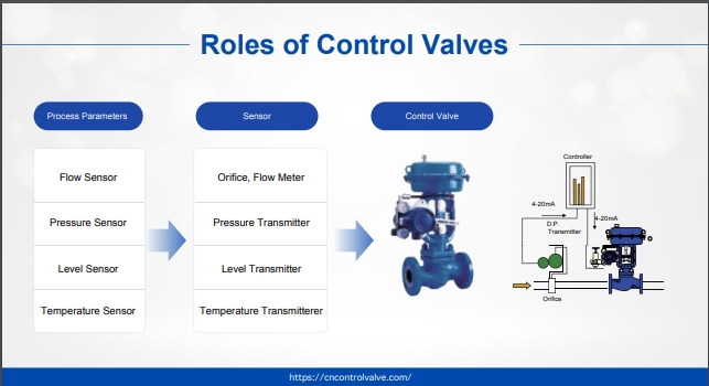
The ability of control valves to reduce process deviations depends on many factors, not just one parameter in isolation, but seven major factors that must be considered by the responsible control valve manufacturer during design selection: Deadband, actuator selection, positioner performance, valve response time, valve type and characteristics, valve selection, etc.
In this article, we focus on what factors affect the response time of control valves and if we avoid the resulting process deviations.
What is the Control Valve Response Time
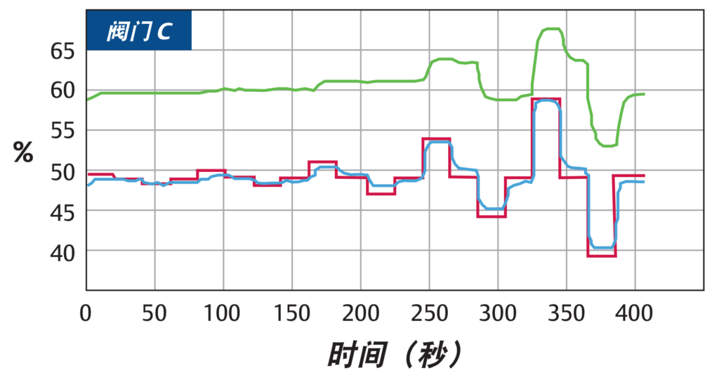
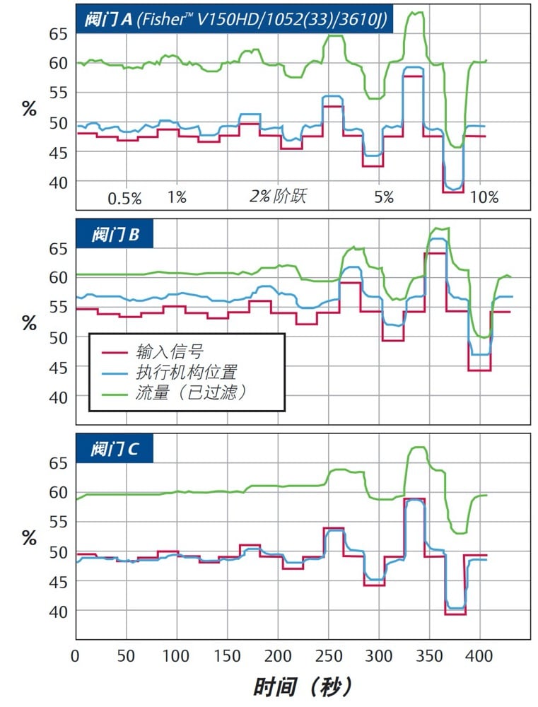
Control Valve response time is measured by a parameter called T63 (Tee-63); T63 is the time measured from the start of a change in the input signal to the time when the output reaches 63% of the corresponding change. It includes the valve assembly stall time as a static time and the dynamic time of the valve assembly. The dynamic time measures the time it takes for the actuator to reach the 63% point after it starts moving.
| Valve Respond Time | |||
| Steps | T(d) Second | T63 Second | |
| Valve Size: 4″ | % | s0.2 | s0.6 |
| Valve A(FisherV150HD/1052(33)/3610J) | |||
| Valve Action: Open | 2 | 0.25 | 0.34 |
| Valve Action: Close | -2 | 0.50 | 0.74 |
| Valve Action: Open | 5 | 0.16 | 0.26 |
| Valve Action: Close | -5 | 0.22 | 0.42 |
| Valve Action: Open | 10 | 0.19 | 0.33 |
| Valve Action: Close | -10 | 0.23 | 0.46 |
| Valve B | |||
| Valve Action: Open | 2 | 5.61 | 7.74 |
| Valve Action: Close | -2 | 0.46 | 1.67 |
| Valve Action: Open | 5 | 1.14 | 2.31 |
| Valve Action: Close | -5 | 1.04 | 2 |
| Valve Action: Open | 10 | 0.42 | 1.14 |
| Valve Action: Close | -10 | 0.41 | 1.14 |
| Valve C | |||
| Valve Action: Open | 2 | 4.4 | 5.49 |
| Valve Action: Close | -2 | NR | NR |
| Valve Action: Open | 5 | 5.58 | 7.06 |
| Valve Action: Close | -5 | 2.16 | 3.9 |
| Valve Action: Open | 10 | 0.69 | 1.63 |
| Valve Action: Close | -10 | 0.53 | 1.25 |
| NR=No Respond |
Control Valve Assembly Design
Differences in valve assembly design result in significant differences in dead time and overall T63 response time.
Deadband, whether from friction in the valve body and actuator or from the positioner, can significantly affect the deadtime of a valve assembly. It is important to keep the dead time as small as possible. In general, the dead time should not exceed one-third of the overall valve response time. However, the relative relationship between the dead time and the processing time constant is critical.
If the valve assembly is in a fast loop where the processing time constant is close to the dead time, the dead time can significantly affect loop performance. In these fast loops, it is critical to select a control device with the shortest possible dead time.
It is also important from a loop tuning perspective that the dead time is relatively consistent in both directions of valve travel. Some valve assemblies are designed with dead times that may be three to five times longer in one direction of travel than in the other.
This type of behavior is usually caused by the asymmetric behavior of the positioner design, which can severely limit the ability to adjust the loop for optimal overall performance.
Actuator and Positioner Characteristics
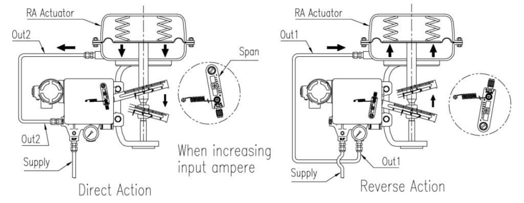
Once the dead time has elapsed, and the valve begins to respond, the remainder of the valve response time comes from the dynamic time of the valve assembly. This dynamic time will be determined primarily by the dynamic characteristics of the positioner and actuator combination.
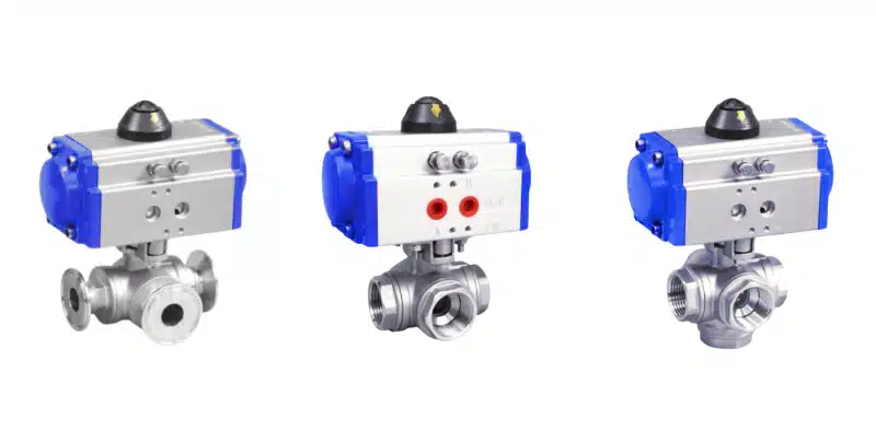
These two components must be carefully matched to minimize the total valve response time. For example, in a pneumatic valve assembly, the positioner must have a high dynamic gain in order to minimize the dynamic time of the valve assembly.
This dynamic gain comes primarily from the power amplification stage in the positioner. In other words, the faster the positioner relay or slide valve supplies large amounts of air to the actuator, the faster the valve response time will be. However, this high dynamic gain power amplifier has little effect on dead time unless it has some intentionally designed deadband to reduce static air consumption. Of course, the design of the actuator can significantly affect the dynamic time. For example, the larger the volume of the actuator air chamber to be filled, the slower the valve response time.
At first, the solution seems to be to minimize the actuator volume and maximize the dynamic power gain of the positioner, but in reality it is not so easy. From a stability standpoint, this can be a dangerous combination of factors. Recognizing that the positioner/actuator combination is its own feedback loop may cause the positioner/actuator loop gain to be too high for the actuator design being used, leading the valve assembly into unstable oscillations.
In addition, reducing the actuator volume can adversely affect the thrust to friction ratio, which can increase the dead time of the valve assembly and thus lead to increased dead time.
If the total thrust to friction ratio is not suitable for a given application, one option is to increase the actuator thrust capacity by using the next size actuator or by increasing the actuator pressure. This higher thrust to friction ratio reduces the dead time, which should help reduce the dead time of the assembly. However, both options imply the need to supply more air to the actuator. The tradeoff is that it adversely affects valve response time by increasing dynamic time.
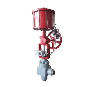
One way to reduce the volume of the actuator air chamber is to use a piston actuator rather than a spring-loaded diaphragm actuator, but this is not a panacea. Piston actuators typically have a higher thrust capability than spring-loaded diaphragm actuators, but they also have higher friction, which contributes to valve response time problems.
In order to get the required thrust with piston actuators, it is usually necessary to use higher air pressure than diaphragm actuators because the piston usually has a smaller area. This means that a larger air volume needs to be supplied, with the attendant detrimental effect on dynamic time. In addition, piston actuators with more guiding surfaces tend to have higher friction due to inherent alignment difficulties and friction from the O-rings. These friction problems also tend to increase over time.
No matter how good the O-rings are initially, these resilient materials will degrade over time due to wear and other environmental conditions. Likewise, wear on guide surfaces increases friction, and lubrication depletion occurs. These friction problems lead to greater piston actuator deadzones, which will increase valve response time by increasing deadtimes.
Air Source Pump Control
The instrument supply pressure can also have a significant impact on the dynamic performance of the valve assembly. For example, it can significantly affect positioner gain as well as overall air consumption.
Fixed gain positioners are typically optimized for a specific supply pressure. However, this gain can vary by a factor of two or more over a small range of supply pressures. For example, a positioner optimized for a supply pressure of 960 Pa (20 psi) may find its gain halved as the supply pressure rises to 1.7 kPa (35 psi).
Supply pressure also affects the amount of air delivered to the actuator, which in turn determines travel speed. It is also directly related to the amount of air consumed. Again, a high-gain slide valve positioner consumes five times the amount of air required by a more efficient high-performance two-stage positioner using relays for the power amplification stage.
In Conclusion
We now know to minimize deadtime in valve components, whether from friction in valve seal design, packing friction, shaft winding, actuator, or positioner design. This is because friction is the primary cause of dead time in control valves.
On rotary valve types, shaft wrap can also significantly affect deadtime. Actuator style also has a profound effect on control valve assembly friction. Typically, spring-loaded diaphragm actuators have less friction on the control valve assembly than piston actuators over a longer period of time.
A positioner design with a high static gain preamplifier can make a significant difference in reducing deadband. This can also significantly improve the resolution of the valve assembly. Valve assemblies with dead zones and resolutions of 1% or less are no longer sufficient to meet many demands for reduced process variability. Many processes require valve assemblies with dead zones and resolutions as low as 0.25%, especially if the valve assembly is installed in a fast process loop.
Selecting the right combination of valve, actuator, and positioner is not easy. It is not just a matter of finding a physically compatible combination. Good engineering judgment must be incorporated into the practice of sizing and selecting valve assemblies to achieve the best dynamic performance of the loop.
Why THINKTANK Control Valve
We know selecting the right combination of control valve, actuator, and positioner is not easy. It is not just a matter of finding a physically compatible combination. As a reliable control valve manufacturer, we will consider good engineering judgment must be incorporated into the practice of sizing and selecting valve assemblies to achieve the best dynamic performance of the loop. If you are looking for good quality control valves, we are the right choice for you. Please do not hesitate to contact us for a free consultation.

