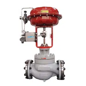
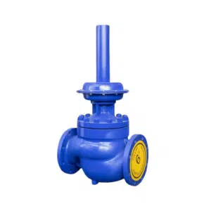
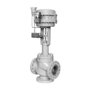
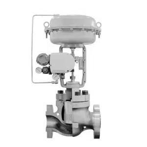
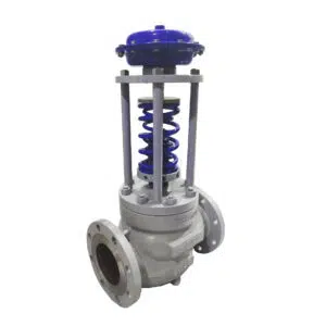
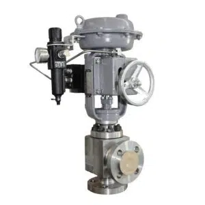
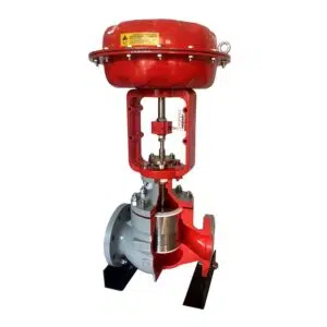
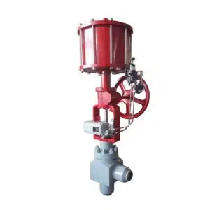
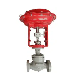
What Is An Automatic Control Valve(ACV)
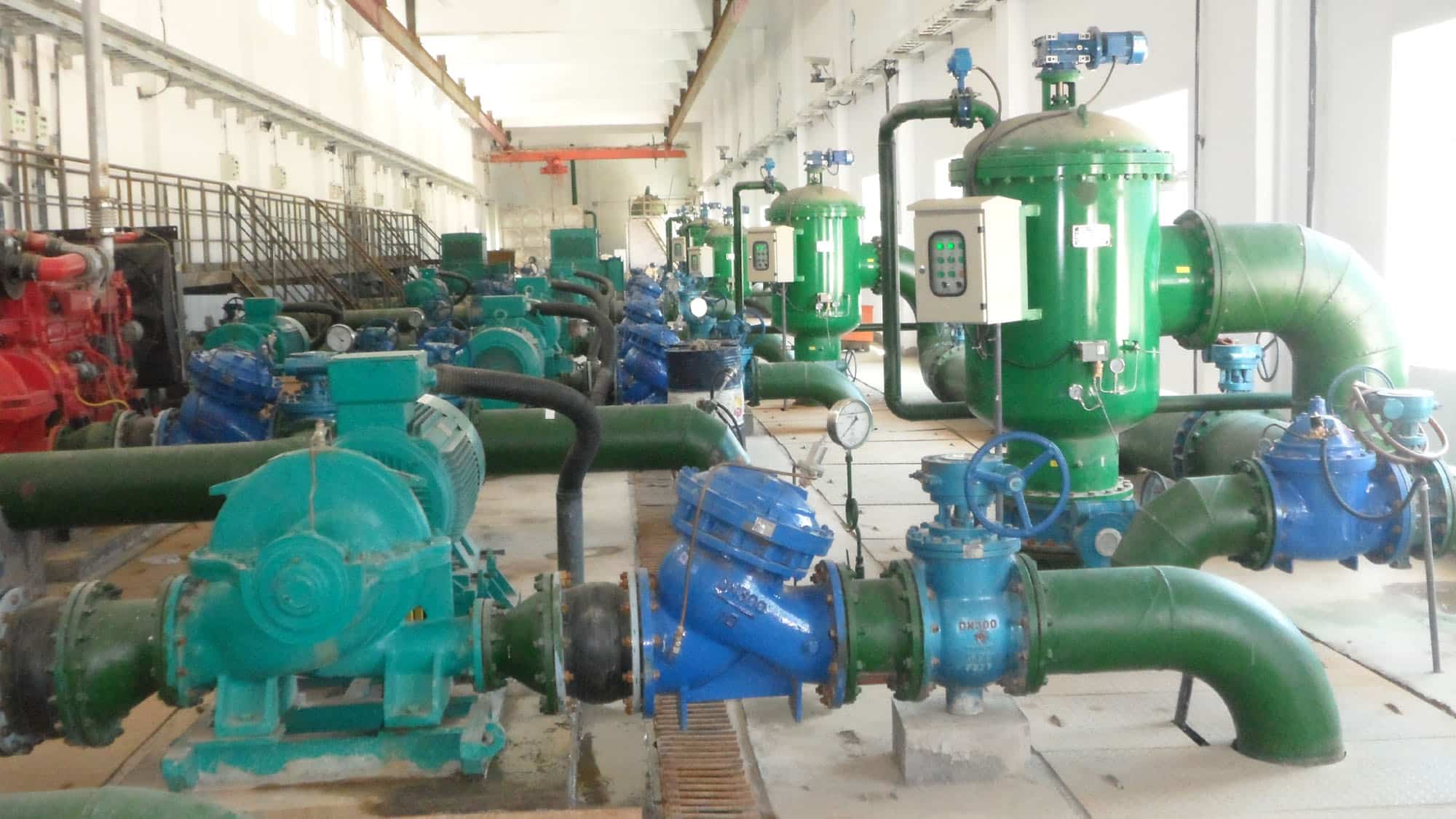
An automatic control valve is also known as a hydraulic control valve, which is a valve that uses the pressure of water in the pipe network to control the opening and closing and adjust the opening of the valve. The automatic control valve not only saves labor, and costs but also power. It is widely used in hydraulic irrigation, high buildings, fire-fighting systems, municipal water supply and drainage, power plants, and other water supply network systems.
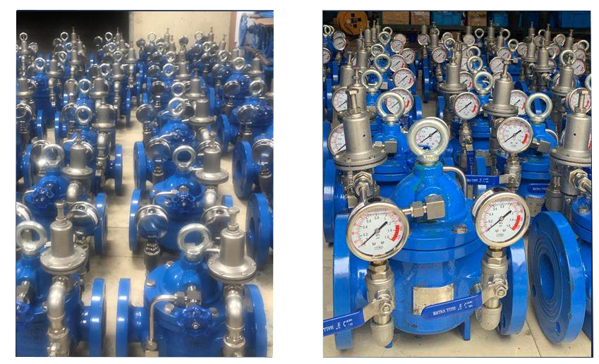
It consists of the main valve and associated tube, needle valve, ball valve, pressure gauge, etc. Based on different functions and working conditions, it can be evolved into a remote float control valve, pressure reducing valve, slow-closing check valve, flow control valve, pressure holding\pressure relief valve, solenoid control valve, pump control valve, differential pressure bypass valve, emergency shut-off valve, pipe force valve, lever float valve, hydraulic automatic valve, multi-spray hole pressure reducing valve, constant water level valve and other products. Especially in waterworks, you can see many types of automatic control valves.
What Is The Automatic Control Valve Function?
The automatic control valves rely on the energy of the medium to automatically control the water level, pressure reduction, pressure relief, pressure holding, regulation, check, eliminate water hammer, switch, and many other functions.
How Does Automatic Control Valve(ACV) Work?
There are many types of automatic control valves, here we take the remote control float control valve as an example to learn its working principle.
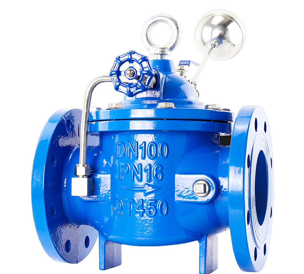
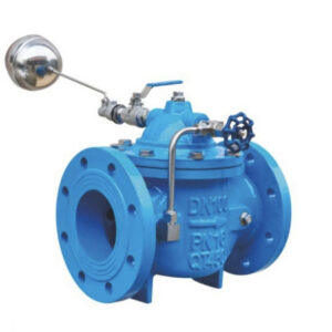
The remote float control valve consists of the main valve and a small float valve. The small float valve acts as a pilot valve and is installed in the tank or pool to determine the installation position according to the level of liquid to be controlled. There are also needle valves and ball valves on the pilot pipe.
The main valve consists of a valve body, valve cover, diaphragm, plug, seat, stem, spring, and other parts.
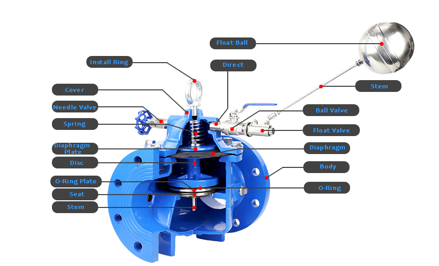
The diaphragm divides the main valve into two upper and lower chambers. Through its pressure difference to achieve the main valve switch control.
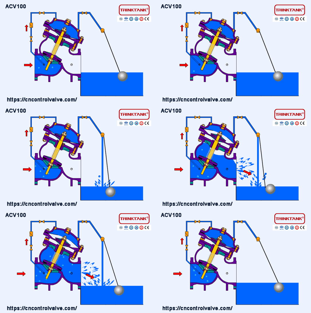
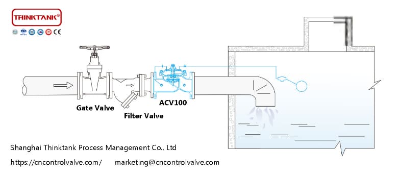
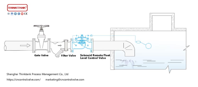
Pipe inlet through the gate valve and filter, into the remote float control valve, the initial state needle valve, ball valve, float control valve is normally open, water through the filter, needle valve, control room, ball valve, float control valve into the tank, at this time the control room does not form pressure, the main valve is open, the water tower ( tank ) water supply. When the water level of the water tower ( tank ) rises to a set height, the float ball floats to close the float control valve, the water pressure in the control room rises, pushing the main valve to close, and the water supply stops. When the water level drops, the float valve reopens, the water pressure in the control room drops, and the main valve opens again to continue the water supply, maintaining the set height of the liquid level.
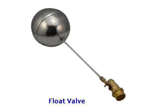
ACV100 Remote Float Control Valve Features & Applications
ACV remote float ball control valve directly uses liquid level control without other devices and energy, easy maintenance, high accuracy of liquid level control, and reliable shutoff. Also, this valve is not affected by water pressure. The remote float ball control valve is widely used for liquid level control in water towers, buildings, waterworks, and other water supply pipeline systems.
In brief, we can describe it in three steps, and the following animation can show the working principle of the valve more vividly.
Step 1. Open the needle valve and ball valve on the tubing, and slowly open the shut-off valve (gate valve) in front of the main valve. The medium in the tubing flows the needle valve, upper chamber, ball valve, and float ball into the tank. The diaphragm upper chamber outlet is not closed to create effective pressure. The main valve opens under the pressure of the medium and starts to supply water to the tank.
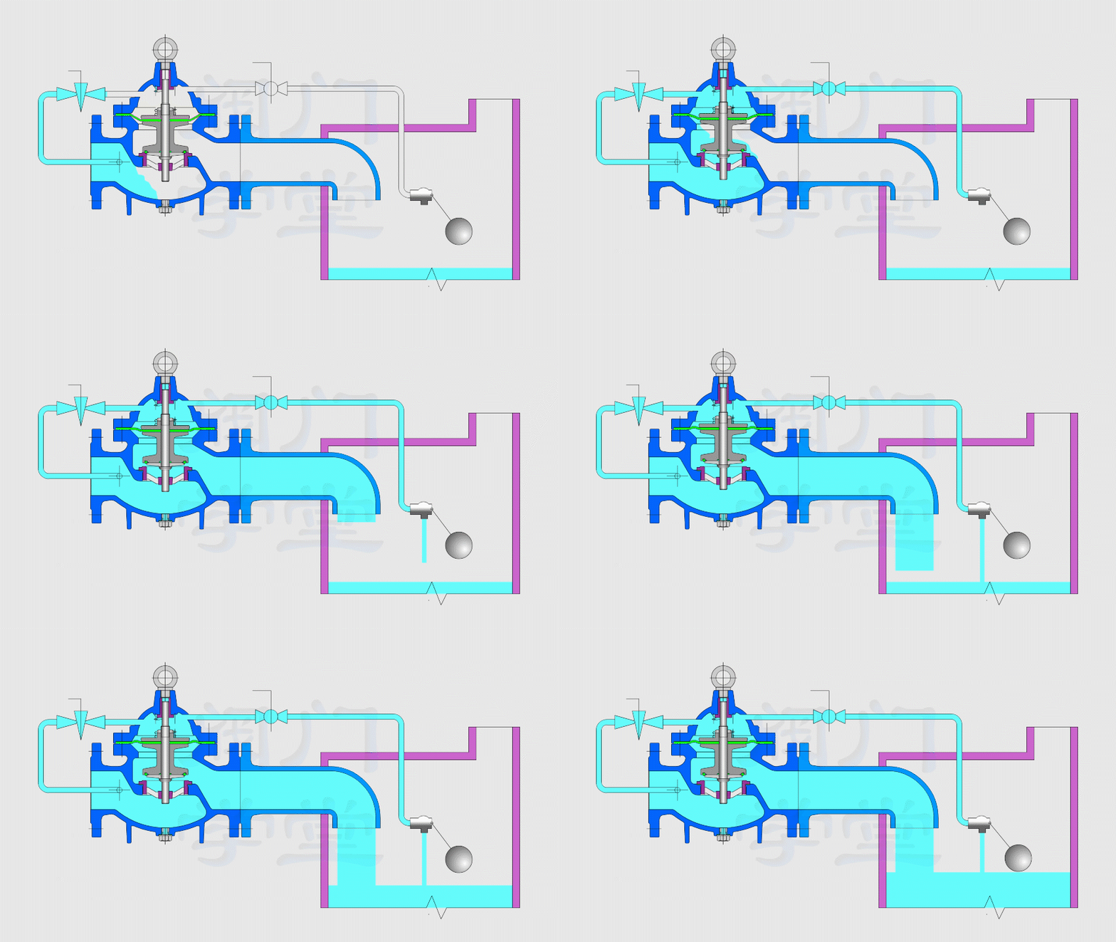
Step 2. As the liquid level in the tank rises, the float valve closes, the diaphragm upper chamber outlet is closed, and the pressure in the diaphragm upper chamber gradually rises, because the area of the diaphragm is larger than the area of the main plug, the differential pressure causes the main valve to gradually close, and the main valve stops supplying water.
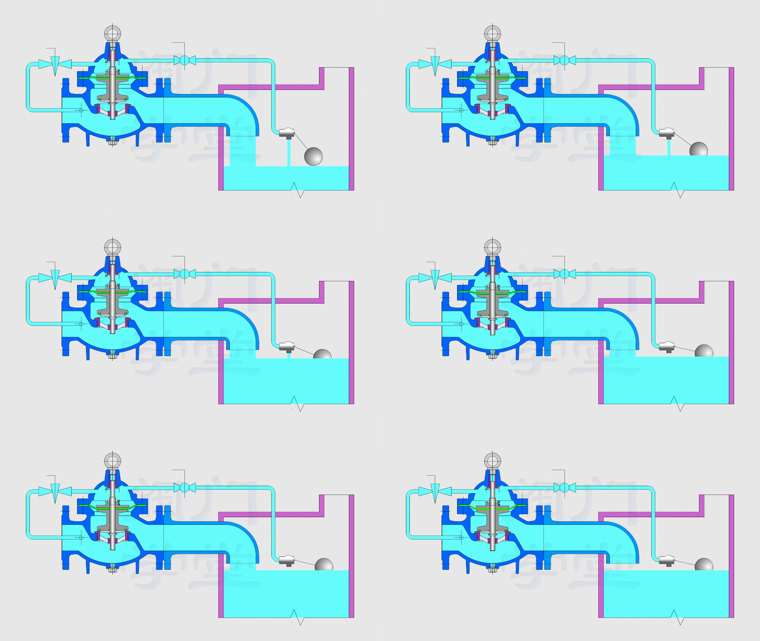
Step 3. When the tank water consumption, the liquid level drops, the float valve opens to drain, the pressure in the upper chamber of the diaphragm gradually decreases, and the main plug opens to supply water under medium power.
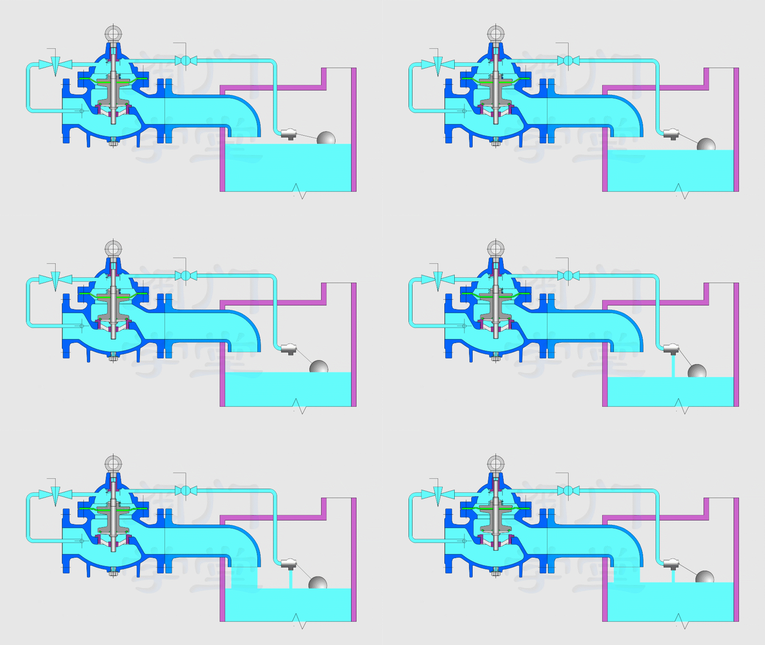
To summarize: the float valve opens when the ball is below the liquid level, and the main valve then opens to start the water supply. When the float valve reaches the liquid level, it closes. The main valve also closes and the water supply stops.
Automatic Control Valve Manufacturer – THINKTANK
There are various types of automatic control valves in THINKTANK, we will introduce them one by one for the material, design, features, application, and installation.
ACV100 Remote Float Control Valve
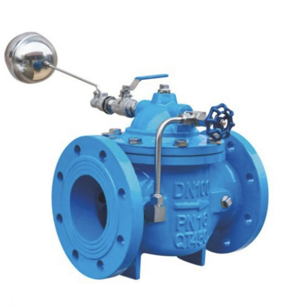
Model: ACV100
Brand: THINKTANK
Size: DN25-DN800
Connection: Flanged Ends
Medium Temperature: 0℃~80℃
Body Material: Ductile Cast Iron, Cast Steel, Stainless Steel
Pressure Rating: PN10, PN16, PN25
Application: It is suitable for the automatic water supply system of commercial electric water boilers, heat pumps, air-conditioning cooling towers, water storage towers, water storage tanks, pools, etc. in high buildings.
Note: Below size DN450 pipeline select diaphragm type, but above DN500 size we recommend customer to select cylinder type.

ACV100 Features
ACV100 remote float control valve is mainly used in pipelines to cut off, distribute and change the flow direction of the medium, it is a kind of hydraulic control valve which is widely used in recent years, and it has the following features.
- Frictionless opening and closing.
- The top-mounted structure is easy to have inspection and maintenance, effectively minimizes device shutdown, and saves costs.
- Single seat design eliminates the problem of abnormal pressure rise in the central chamber which affects safety.
- Low torque design. In the special structure design of the valve stem, only a small handle valve can easily open and close.
- Wedge seal structure. The valve is sealed by the mechanical force provided by the valve stem, which wedges onto the valve seat so that the sealing of the valve is not affected by the change of differential pressure in the pipeline, and the sealing performance is reliably guaranteed under various working conditions.
- Self-cleaning structure of sealing surface. When the ball is tilted away from the seat, the fluid in the pipeline along the ball sealing surface into 360 ° uniform passage, not only eliminates the high-speed fluid on the seat of the local scouring but also flushes away the accumulation on the sealing surface, to achieve the purpose of self-cleaning.
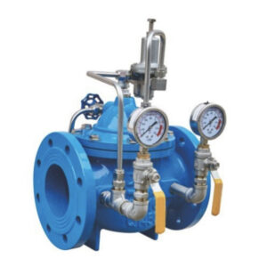
ACV200 Pressure Reducing Valve
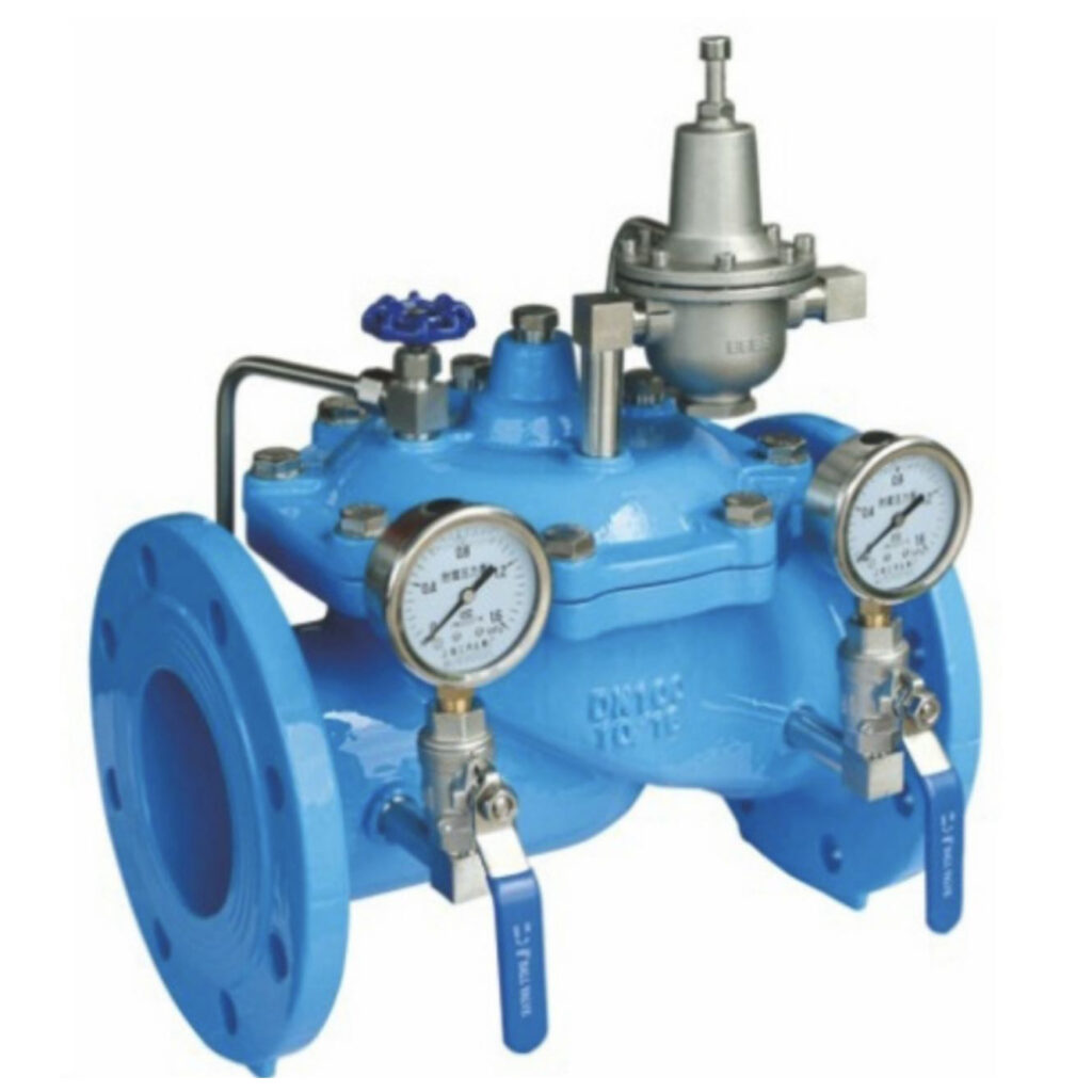
Model: ACV200
Size: DN25-DN800
Pressure Rating: PN10, PN16, PN25
Connection: Flanged Ends
Medium Temperature: 0℃~80℃
Body Material: Ductile Cast Iron, Cast Steel, Stainless Steel
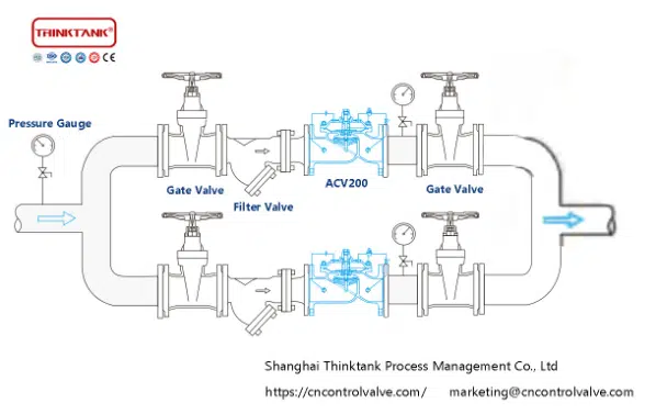
ACV200 Pressure reducing valve is a kind of valve used in the parallel water supply system of firefighting and lives, which is used to deploy the direction of water supply. When a fire breaks out and a large amount of water is urgently needed for fire fighting, the domestic water supply is immediately cut off to ensure sufficient water for fire fighting. When the fire fighting stops and the water pressure decreases, the valve automatically opens to resume the domestic water supply. The valve makes the system not need to set up a special separate water supply pipeline for firefighting, which greatly saves construction costs and water consumption.
ACV300 No-Slamming Hydraulic Check Valve
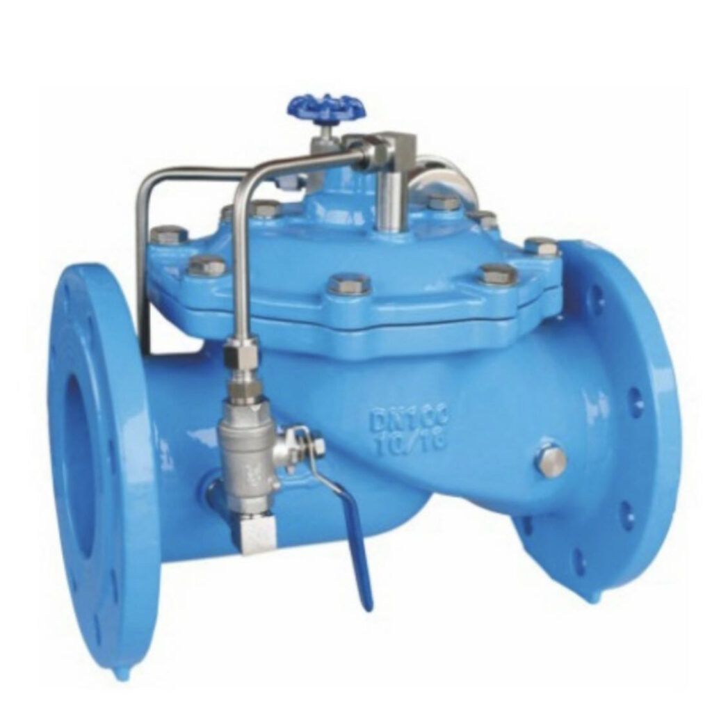
Model: ACV300
Size: DN40-DN800
Pressure Rating: PN10, PN16, PN25
Connection: Flanged Ends
Medium Temperature: 0℃~80℃
Body Material: Ductile Cast Iron, Cast Steel, Stainless Steel
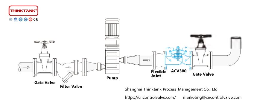
ACV300 No-Slamming hydraulic check valve is a kind of slow-closing check valve which consists of the main valve, check valve, needle valve, ball valve, microform filter, and pressure gauge. Using hydraulic automatic operation, it can make the main valve get the best opening and closing speed. Prevent water hammer caused by valve slamming at closing, in order to achieve the effect of slow closing and silencing.
Installation and Adjustment
- The best installation direction of the main valve is horizontally mounted on the pipeline with the valve cover facing upward.
- Before installation, we should remove debris from the pipeline, and pay attention to the arrow markings on the main valve body when installing, the arrow represents the direction of water flow.
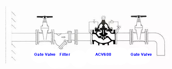
- The upstream of the main valve should install a gate valve and a filter valve, and a gate valve should also be installed downstream for maintenance purposes.
- The pipeline must be completely blown and cleaned before the water is turned on, so as to discharge impurities, iron particles, and other solid particles outside the pipe.
- When testing water, slowly open the gate valve inlet of the main valve and slowly increase the pressure, while paying attention to whether the control tubing outside the main valve body is leaking.
- The microfilter on the main valve is mainly used to clean the needle valve. The needle valve and ball valve with adjustment can get the best performance of opening and closing speed.
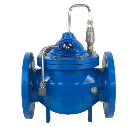
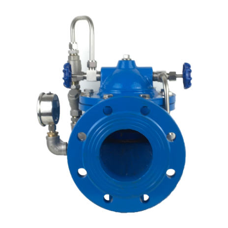
ACV400 Flow Control Valve
Model: ACV400
Size: DN25-DN800
Pressure Rating: PN10, PN16, PN25
Connection: Flanged Ends
Medium Temperature: 0℃~80℃
Body Material: Ductile Cast Iron, Cast Steel, Stainless Steel
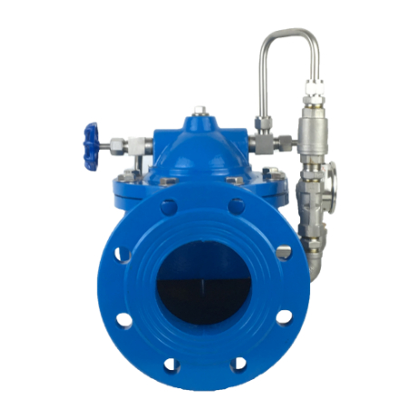
Flow control valves are used in pipelines where the distribution pipe needs to control the flow and pressure, keeping the predetermined flow constant, limiting the excessive flow to a predetermined value, and reducing the upstream high pressure appropriately, even if the pressure upstream of the main valve changes, it will not affect the flow downstream of the main valve. In case of emergency, the ACV400 flow control valve can cut off the flow to avoid losses. It has high control sensitivity, safety & reliability, easy commissioning, and long service life.
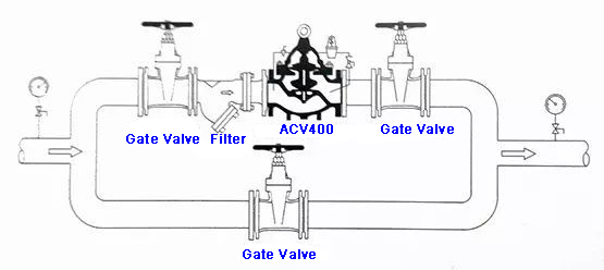
Features and Application ACV400
The ACV400 flow control valves use hydraulic self-control, no other devices and energy, easy maintenance, and stable flow control. This series of control valve products are widely used in high buildings, domestic areas, and other water supply pipeline systems and city water supply projects.
Maintenance Instructions For Flow Control Valve
The hydraulic control valve is a self-lubricating valve body using water, without the need for additional oil lubrication, if you experience damage to the internal parts of the main valve, according to the following instructions for disassembly.
- Close the gate valves upstream and downstream of the main valve.
- Loosen the screws of the piping connector on the main valve cover to relieve the pressure inside the valve.
- Remove all screws, including the necessary copper tubing and nuts in the control line.
- Remove the cover and spring.
- Remove the plug, diaphragm (piston), etc. Please be careful and do not damage the diaphragm.
- Check if the diaphragm and gasket are damaged, if not, please do not disassemble the internal parts.
- If you find that the diaphragm or gasket is damaged, please loosen the nut on the plug, disassemble the diaphragm or gasket piece by piece, and then replace it with a new one.
- Check all detail whether there is damage to the valve seat and plug inside the main valve, and if there is other debris in the main valve, clean it all up.
- Assembly the replaced parts in reverse order and install the main valve, paying attention to the valve must not being stuck.
- Please refer to the installation operation notes to reuse.
ACV500 Pressure Relief/Sustaining Valve
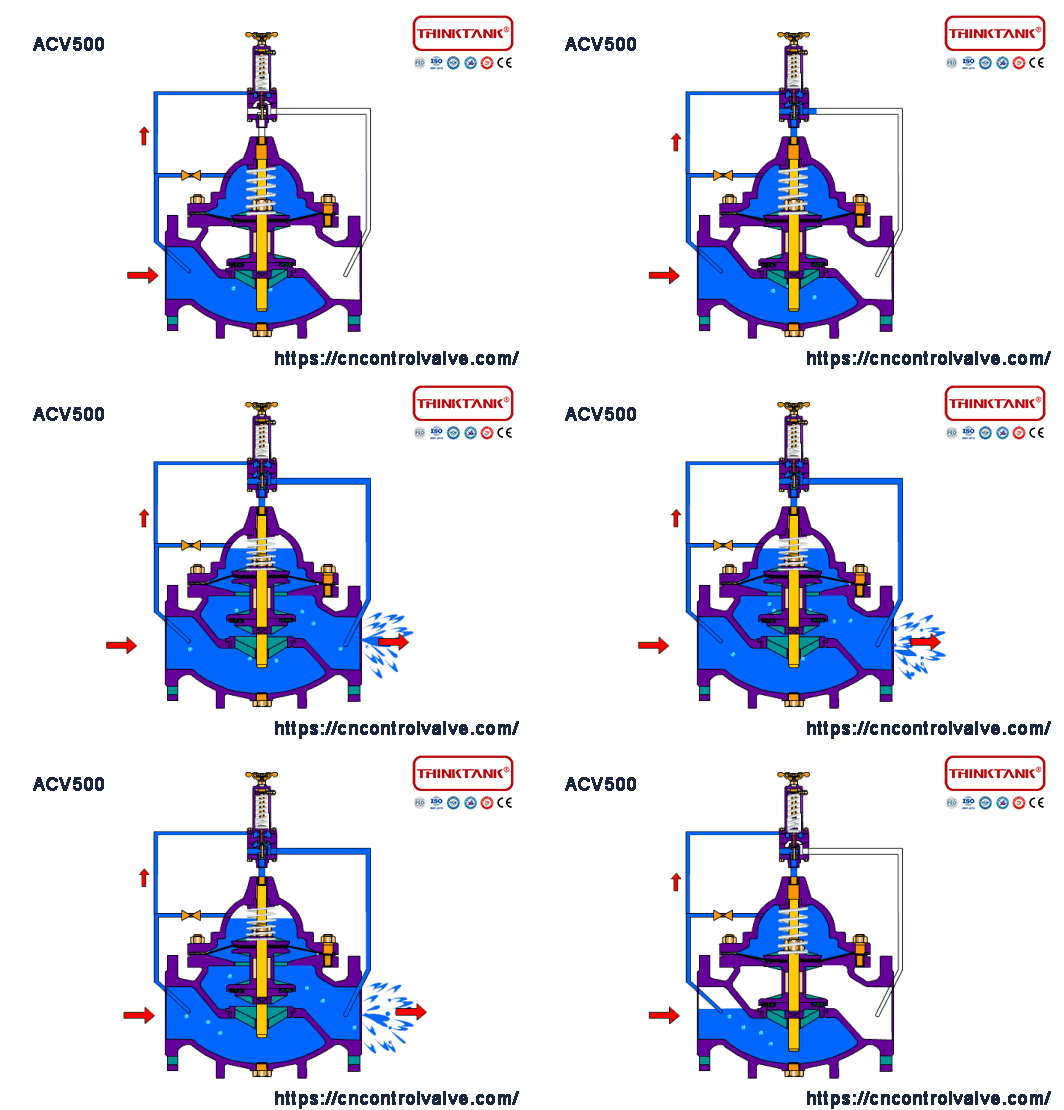
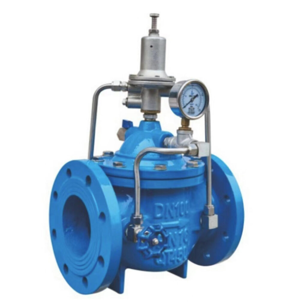
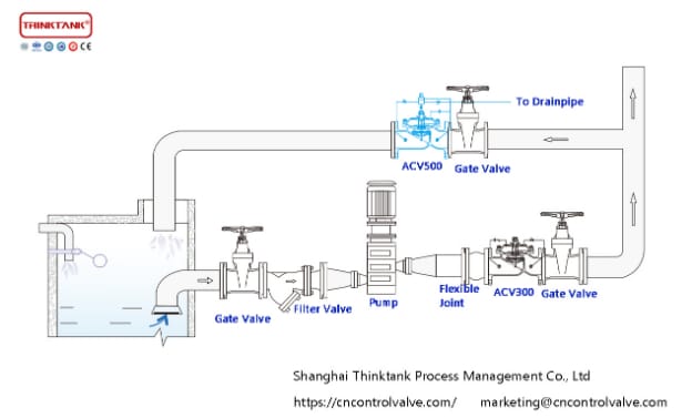
Model: ACV500
Size: DN25-DN800
Pressure Rating: PN10, PN16, PN25
Connection: Flanged Ends
Features
The pressure relief/sustaining valve consists of the main valve, pressure relief/sustaining pilot valve, needle valve, ball valve, microform filter, and pressure gauge. It can be used as both a pressure relief valve and a pressure sustaining valve by automatic hydraulic operation. When used as a pressure relief valve, the pressure in the water supply line can be maintained below the set safety value; when used as a pressure sustaining valve, the water pressure upstream of the main valve can be maintained above the set value to keep the water supply pressure upstream of the main valve.
ACV600 Electronic/Solenoid Flow Control Valves
Model: ACV600
Size: DN25-DN800
Pressure Rating: PN10, PN16, PN25
Connection: Flanged Ends
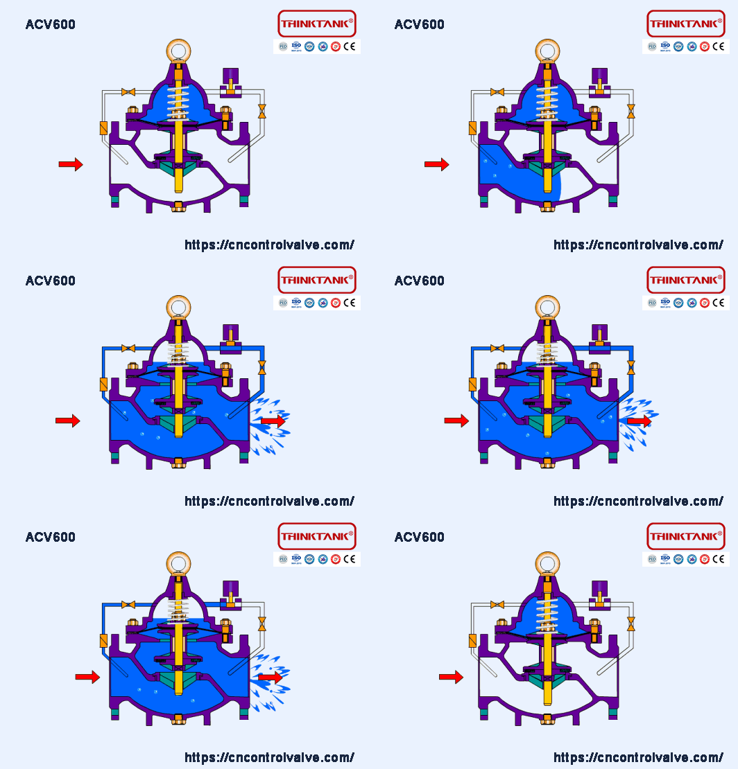
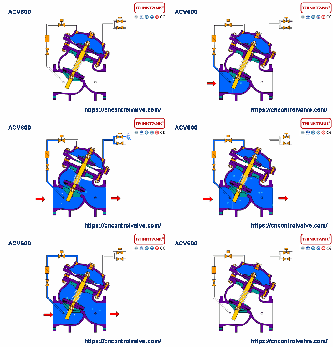
The electronic water control valve(solenoid control valve) is a hydrodynamic operated valve with a solenoid valve as the pilot valve. Commonly used for automatic control in water supply and sewage and industrial systems, the control response is accurate and fast. According to the electric signal remote control to open and close the pipeline system, to achieve remote operation.
ACV700 Pump Flow Control Valves
Model: ACV700
Size: DN50-DN800
Pressure Rating: PN10, PN16, PN25
Connection: Flanged Ends
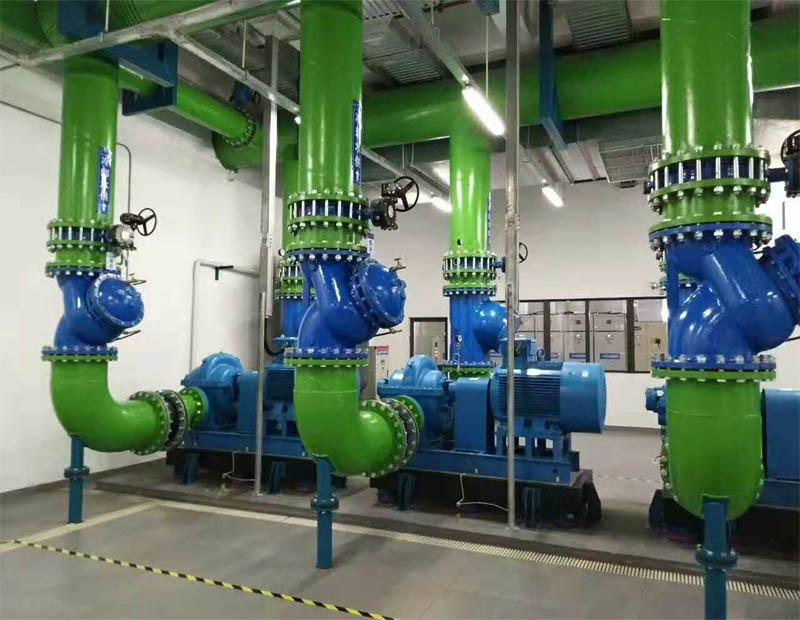
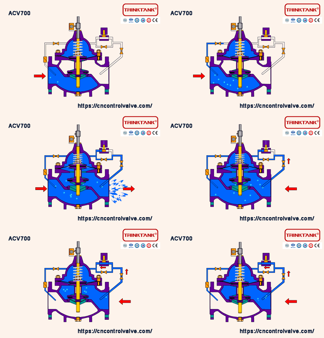
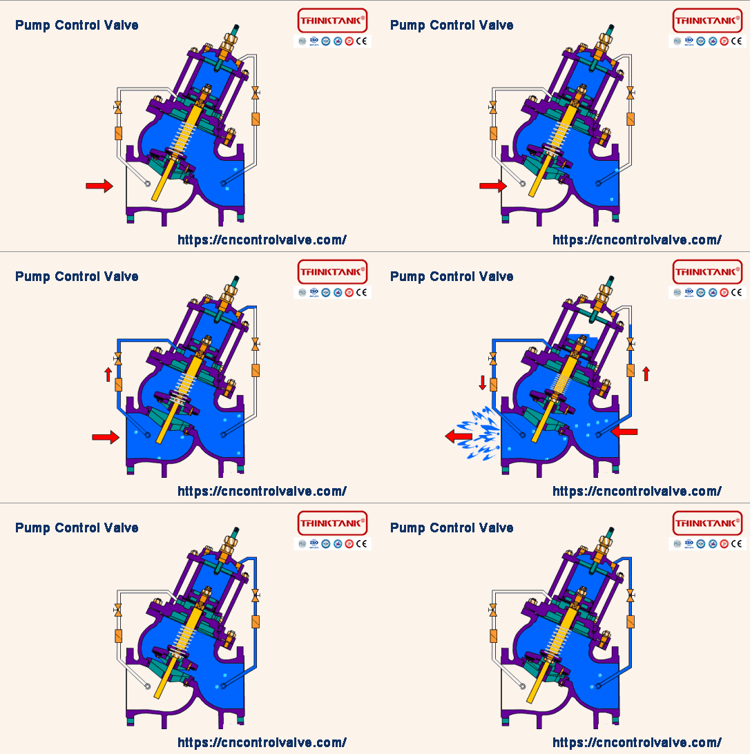
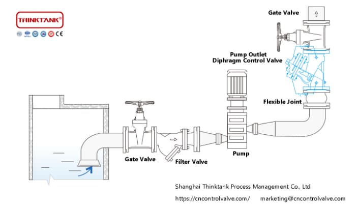
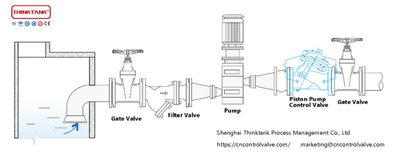
A water pump control valve is a kind of hydraulic control valve, pump control valve consists main valve and its attached conduit, pilot valve, needle valve, ball valve, pressure gauge, and other components. According to the purpose, function, and application can evolve into remote control float valve, pressure reducing valve, no slamming hydraulic check valve, flow control valve, pressure relief valve, hydraulic electric control valve, pump control valve, etc. Water pump control valves in the pipeline generally are installed horizontally direction, and upstream should be installed a filter valve, in order to easy to drain.
ACV800 Differential Pressure Bypass Control Valves
Model: ACV800
Size: DN50-DN800
Pressure Rating: PN10, PN16, PN25
Connection: Flanged Ends
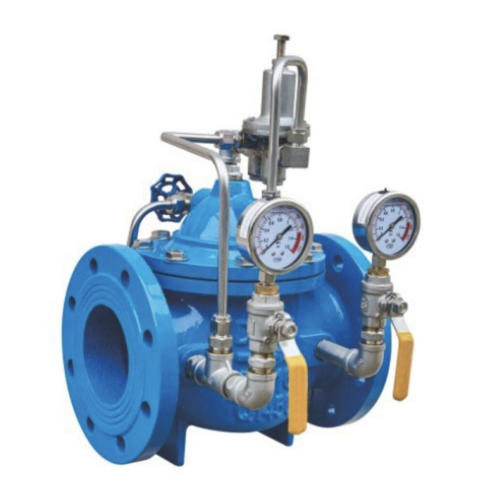
The differential pressure bypass valve is mainly used in air conditioning systems where has a differential pressure between the supply water and the feedback water, and it is set at a fixed value. The differential pressure bypass control valve can improve the utilization of the system, reduce noise, and prevent damage to system equipment from excessive differential pressure.
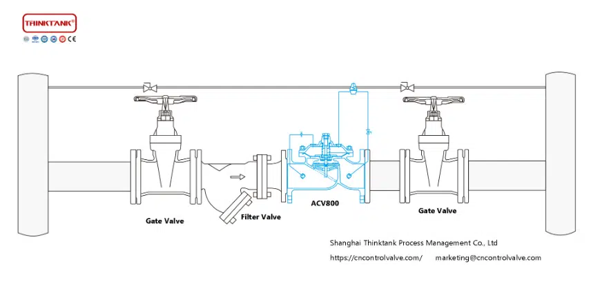
Installation of the Differential Pressure Bypass Valve
- The differential pressure bypass valve needs to be loaded and unloaded carefully, it is recommended to lift it with soft rope to avoid damaging the valve and piping, to protect the coating layer, and the valve should be placed on the ground carefully and gently.
- check before installation: after loading and unloading to the destination, first check the contents of the manual to confirm whether the piping is correct, whether the connection is reliable, whether there is any damage to the valve during transportation, and whether the various parts are complete.
- Before installation, clean up the debris in the pipeline, check the corresponding flange and the valve flange pressure level, nominal diameter in line, and keep the pipeline smooth.
- Before and after the differential pressure balancing valve, two gate valves should be installed to facilitate detection and maintenance.
- The differential pressure pilot valve should be directly connected to the supply pipeline and feedback pipeline, in order to achieve an accurate response to the differential pressure between supply water and feedback water, for the convenience of installation and use, a ball valve can be installed on the sensing pipeline.
Instructions for use of Differential Pressure Bypass Valve
- Check that all gate valves, ball valves, and needle valves are fully open before use.
- Observe the pressure between supply/return, adjust the differential pressure pilot valve according to the differential pressure value, unscrew the top cap on the pilot valve, and use a wrench to rotate the top screw, from top to bottom, the differential pressure increases when rotating clockwise and decreases when rotating counterclockwise, according to the desired value to rotate times, when the differential pressure reaches the required value, screw the top cap and run for a while, regardless of the pressure change in the pipeline, ensure that it is at the set differential pressure value.
- The action speed of the main valve can be adjusted by the needle valve, the action slows down when rotating clockwise, and speeds up when rotating counterclockwise. Usually, the needle valve has been set before delivery, so it no needs to adjust again.
ACV900 Quick Pressure Relief Valves
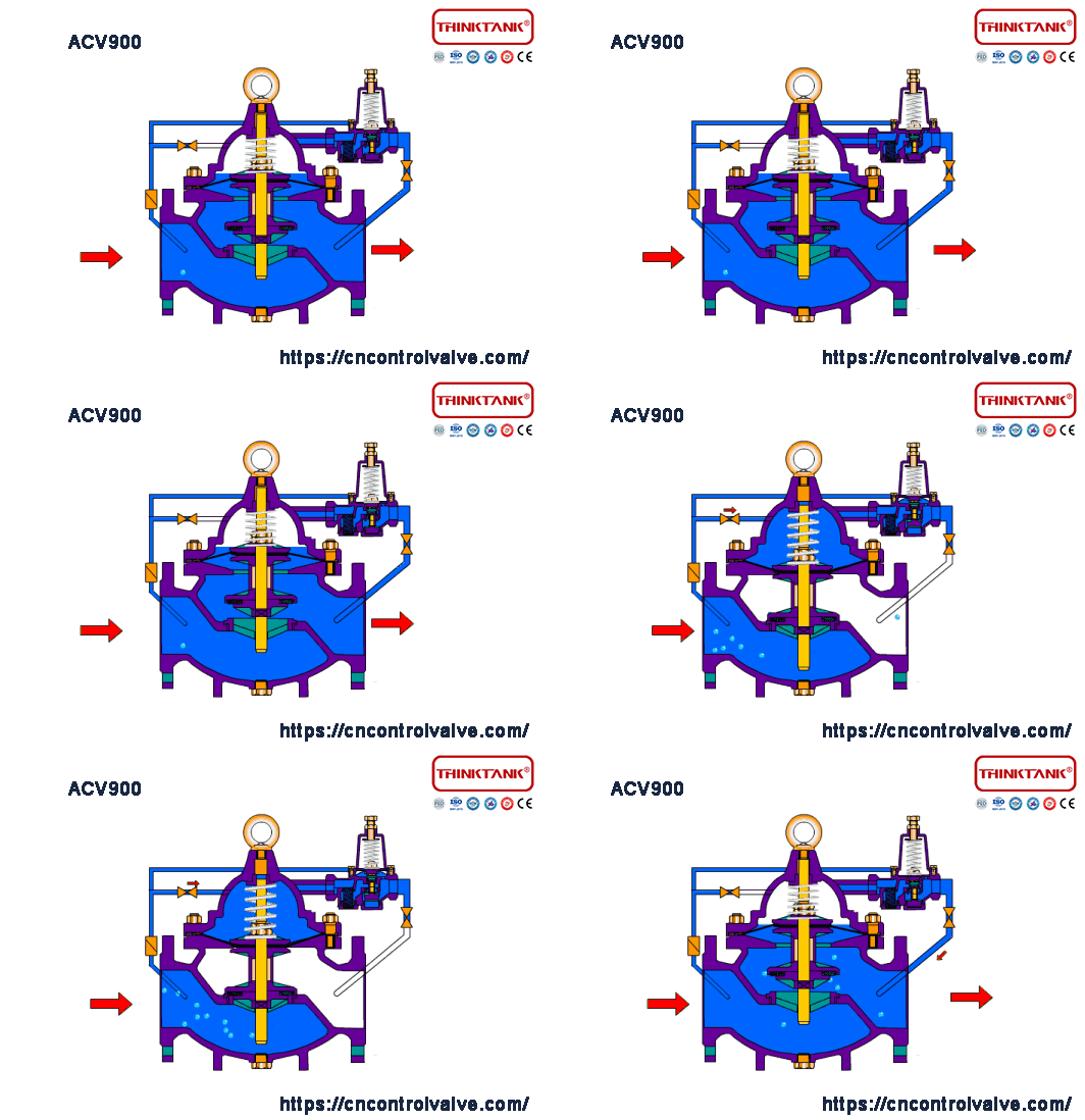
Model: ACV900
Size: DN25-DN800
Pressure Rating: PN10, PN16, PN25
Connection: Flanged Ends
The quick pressure relief valve is a kind of emergency shut-off valve used in the water supply system where fire-fighting water and domestic water are connected in parallel and used to deploy the direction of the water supply. When a fire occurs, firefighting urgently needs a large amount of water, and immediately cut off the domestic water to ensure sufficient water for firefighting; when firefighting stops water pressure decreases, and the valve automatically opens and is normally open to restore the domestic water supply.
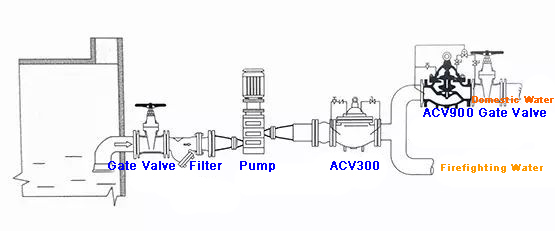
The emergency shut-off valve makes the system no need to set up a special fire-fighting separate water supply network, which greatly saves construction costs and water consumption. Valve control sensitivity is high, safe and reliable, easy to debug, and long service life.
The Problem and Solution For Float Level Control Valve Can Not Be Closed
Find the reason why the float valve can not shut off the water, you typically need to drain the water first, and then check the accessories inside, especially to check if the float ball is damaged or sensitivity failure, etc., and then targeted to solve the problem. The float valve can not shut off the water for the following reasons.
1. There is a water leakage
2. The line connection
3. The float lever is stuck
4. Float ball movement track
5. Seal wear
6. Inlet valve control lever sensitivity
7. Water buoyancy
8. Water valve has special objects
So the above points of the phenomenon, how to check which of the above causes and how to solve it.
- Unscrew the float ball, and check whether there is a leak. If there is a leak, replace the float with a new one or use tape to wrap the leaking place.
- Check whether there is a problem with the line connecting the switch position, if the wire is disconnected it cannot reach transmitting signals and will not be able to turn off the water.
- Check whether the float lever is stuck or whether the connecting bolt is too loose. If there is a stuck situation, you need to loosen the connecting bolts and adjust the position of the float lever; if the float lever is loose, you need to use a screwdriver to re-tighten the screws on the float lever;
- Check whether the float ball is too narrow at the movement gauge. If the movement range is narrow, it will certainly obstruct the whole float ball movement direction, causing the float valve can not shut off the water.
- Check whether the seal is seriously worn, if yes, just replace the seal.
- Check whether the inlet valve control lever linked to the ball is sensitive. If not sensitive, need to replace the ball lever.
- The buoyancy of the water is not enough, need to check the pressure problem, and you can properly increase the length of the floating ball lever.
- The water valve has a special object, such as water embroidery, but also may be some damaged parts, such as screws, shafts, and so on.
8 Points You Need To Pay Attention To Hydraulic Control Valves in The Waterworks
NO 1. Technical Inspection And Mill Test Report
The application of hydraulic control valves must be qualified by the manufacturer’s inspection, a variety of signs complete, and technical data meet the requirements.
NO 2. Type, Material, And Functional
Based on the functional requirements, select the type of hydraulic control valve, and then according to the pipeline transport medium, temperature, building standards, and the requirements of the end-users, etc., determine the valve body and sealing parts of the material. Commonly valve body materials are cast iron, copper iron, brass, PVC, etc., and sealing and lining materials are brass alloy, plastic, steel, cemented carbide, rubber, etc. The valve body material should match the pipeline material.
NO 3. Nominal Pressure
The nominal pressure of the hydraulic control valve has 0.6, 1.0, 1.6, 2.5, and 4.0MPa. The working pressure should be less than the nominal pressure, and the safety factor should be more than 35%.
NO 4. Installation Space
Hydraulic control valves in the project should be set up with sufficient space for management, operation, installation, and maintenance, and should meet the requirements of the pipeline to the valve.
NO 5. Connection Type
If the pipeline uses flanged ends, then the hydraulic control valve should also use flanged ends. If the pipeline uses groove ends, then the valve should use groove ends also.
NO 6. One-Way Condition
The hydraulic control valve should be set in the medium one-way flow of the pipeline.
NO 7. Arrow Direction
The hydraulic control valve on the main body of the arrow direction must be consistent with the flow direction of the pipeline system.
NO 8. Air Vent Valve
The pipe section connected to the hydraulic control valve should not have air plugging, or gas blocking phenomenon. In the high position of the pipe network and other air storage sections should be set up automatic air vent valve.
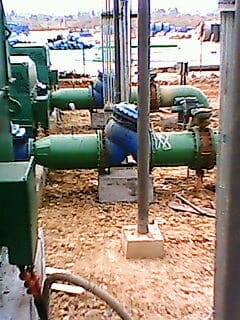
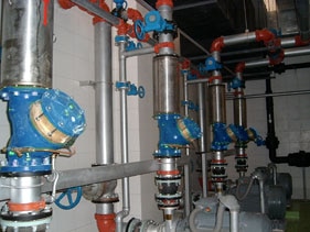
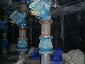
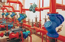
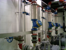
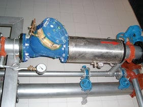
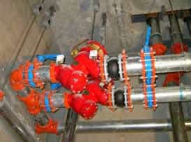
Conclusion
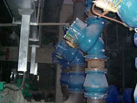
The above content does not cover all the knowledge of hydraulic control valves. THINKTANK engineers will expand the content to the specific applications and projects of each model step by step. THINKTANK has many years of experience in manufacturing hydraulic control valves, if you have any questions or purchasing demands, please feel free to contact our sales representatives.
