Sizing a level control valve correctly is essential for having an effective system. A level control valve is used to manually or automatically regulate the flow of liquid in a liquid-level system. The size of the valve depends on various factors, such as the type of medium regulated, the required flow rate, pressure drops, and line size and length.
The first step in sizing a level control valve is to determine its application. For this purpose, you need to consider the type of media being controlled, its characteristics (such as viscosity), system design parameters such as curve slopes, and other important considerations like pressure drops and line length. Once these details are established, you can proceed with finding the optimal valve size that will meet your requirements.
Next, it’s important to establish the operating range for the level control valves, including their minimum, normal, and maximum flow rates and maximum pressure drops across the valve. This information should be available in the manufacturer’s specifications or engineering design. You should also consider any shutoff or throttling requirements you might have because this affects how far apart the minimum and maximum pressure drops must be set in order for your system to operate properly.
Finally, select a valve size that best meets your requirements while staying within its stated operating parameters. Once all these steps are completed, you can install the level control valve into your system and adjust its setting accordingly for proper operation.
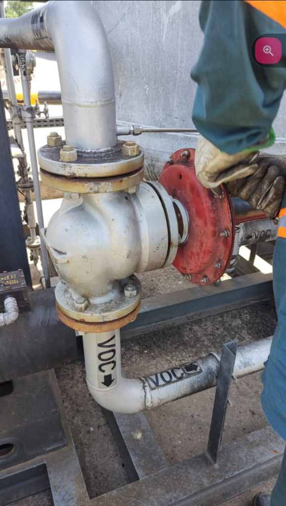
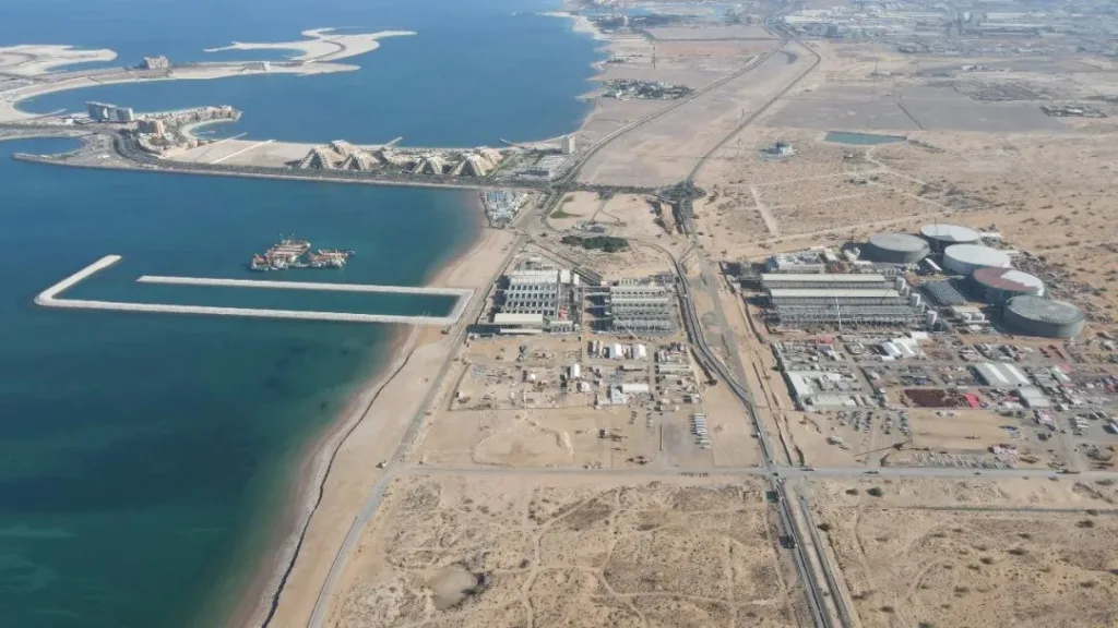
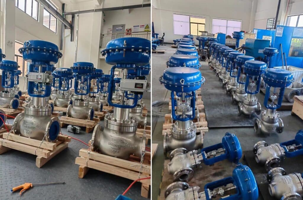
LCV(Level Control Valve) Used Separator System
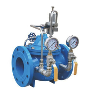
Level control valves are everywhere in the separator system, we just listed one sample from a chemical plant. The separator pressure is 75 psig and the downstream of LCV goes to a vessel where pressure is maintained by blanketing at 5 psig. From figure 1 you can see an LCV is from a separator. Here we are going to discuss what DP drop pressure should be considered for the level control valve? should be just simple 75psig – 5 psig = 70psig ? or we need to consider pressure drop across the piping for the downstream of LCV?
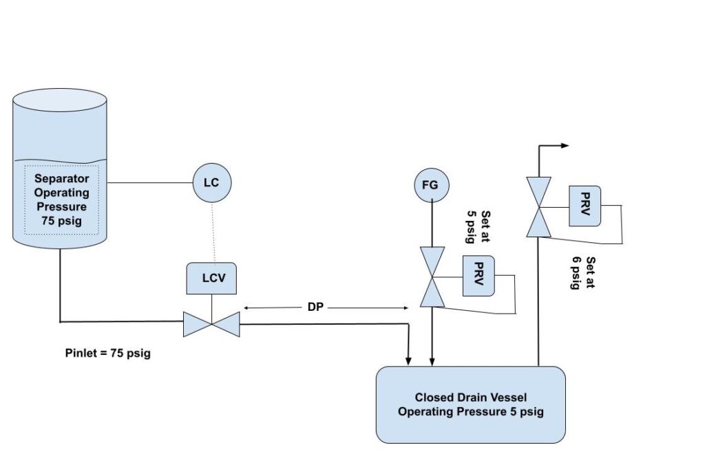
For this case 75 psig upstream pressure and 5 psig downstream pressure will get you close enough. The LCV will modulate to regulate the flow. If we really wanted to be meticulous, we’d do a full pressure balance that would look something like this.
Upstream pressure = vapor static pressure (75 psig) + liquid head – line losses
Downstream pressure = vapor static pressure (5 psig) + line losses
But the actual operating conditions are going to vary from what you anticipate, especially during startup.
Increasing the downstream pressure may or may not affect the capacity of the valve. If the valve is still operating under choked conditions, capacity is not affected. However, if the downstream pressure rises above the choke point, the valve will need to open further to pass the same amount of flow.
We should consider the pressure drop across the piping (and the liquid head) if they can be significant. They may not be significant compared to the 70 psi difference in operating pressure between the vessels.
The pressure downstream of the LCV will depend on the operating pressure of the downstream vessel and the backpressure due to flow from the CV to the vessel.
If the pressure downstream of the LCV rises, the level will start to back up, and the CV will open more to reduce the system dP to compensate. This is the purpose of having a control valve.
3 Steps for Sizing Control Valves for Liquids Fluid
The IEC technique for sizing control valves for liquid flow is detailed in the steps that follow. During any valve sizing operation, each of these phases is crucial and must be addressed. Steps 3 and 4 include the identification of specific sizing parameters that, depending on the service circumstances of the size problem, may or may not be required in the sizing equation. Refer to the relevant factor determination section(s) in the text following the sixth step if one, two, or all three of these size factors need to be included in the solution for a particular sizing problem.
Step 1: Specify the following variables needed to size Level Control valve
• Desired design
• Fluid of operation (water, oil, etc.)
• Appropriate service conditions q or w, P1 or P2, P, T1 or Gf or Pv or Pc.
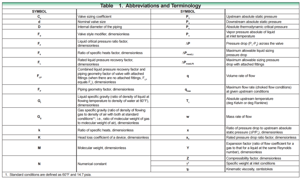
Experience with a variety of valve sizing issues is required to understand which phrases are appropriate for a particular size technique. Refer to the Abbreviations and Terminology Table 1 for a comprehensive explanation of any unknown or unfamiliar-appearing words.
Step 2: Determine the constant N in the equation.
N is a numerical constant used in each of the flow equations to facilitate the use of different unit systems. In Equation Constants Table -2, the values and units for these different constants are provided.
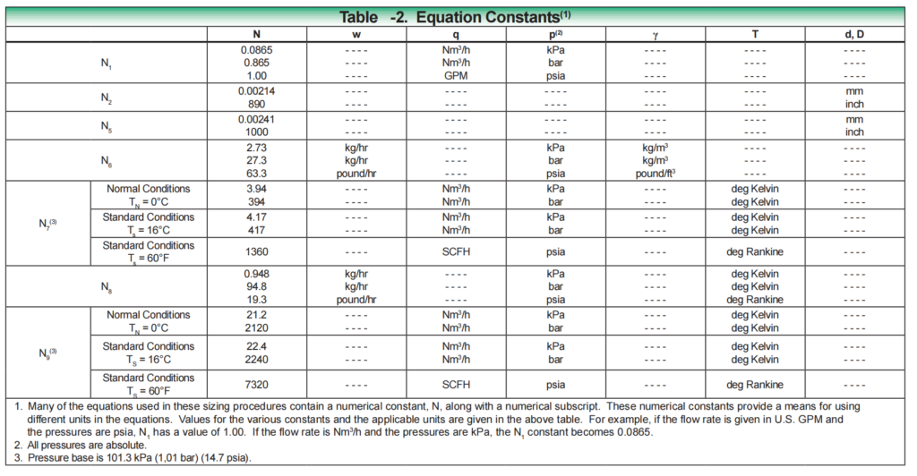
Use N1 if the flow rate is expressed in volumetric terms (gallons per minute or Nm3 per hour).
Utilize N6 if the flow rate is expressed in mass units (lb/hr or kg/hr).
Step 3: Determine the pipe geometry factor, Fp.
Fp is a correction factor that accounts for pressure losses caused by pipe fittings such as reducers, elbows, and tees that may be linked directly to the inlet and outlet connections of the to-be-sized control valve. In the sizing method, the Fp factor must be addressed if such fittings are attached to the valve.
If no fittings are linked to the valve, however, Fp has a value of 1 and is eliminated from the sizing calculation.
Determine the Fp factors for rotary valves with reducers (swaged installations) and other valve designs and fitting styles using the process for computing Fp, the Piping Geometry Factor.
Step 4: Determine qmax (the maximum flow rate under specified upstream circumstances) or Pmax (the allowable sizing pressure drop).
The maximum or limiting flow rate (qmax), also known as choked flow, is characterized by no increase in flow rate with rising pressure difference and constant upstream circumstances. In liquids, choking happens when the static pressure within the valve falls below the liquid’s vapor pressure, causing the liquid to evaporate.
To account for the potential of blocked flow conditions within the valve, the IEC standard stipulates the computation of a maximum permitted pressure drop (Pmax). The sizing equation utilizes the smaller of the computed Pmax value and the actual pressure drop given under service circumstances. Pmax can be computed using the method for finding qmax, the Maximum Flow Rate, or Pmax, the Allowable Sizing Pressure Drop, if it is desirable to account for the potential of blocked flow circumstances. If it is known that choked flow conditions will not develop within the valve, it is not necessary to compute Pmax.
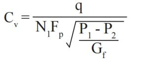
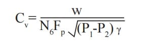
Step 5: Solve for the necessary Cv using the correct equation
• For units of volumetric flow rate,
• Regarding mass flow units:
In addition to Cv, Kv and Av are also employed as flow coefficients, mainly outside of North America. Existence of the following relationships:
Kv = (0.865) (Cv)
Av = (2.40 x 10⁻⁵) (Cv)
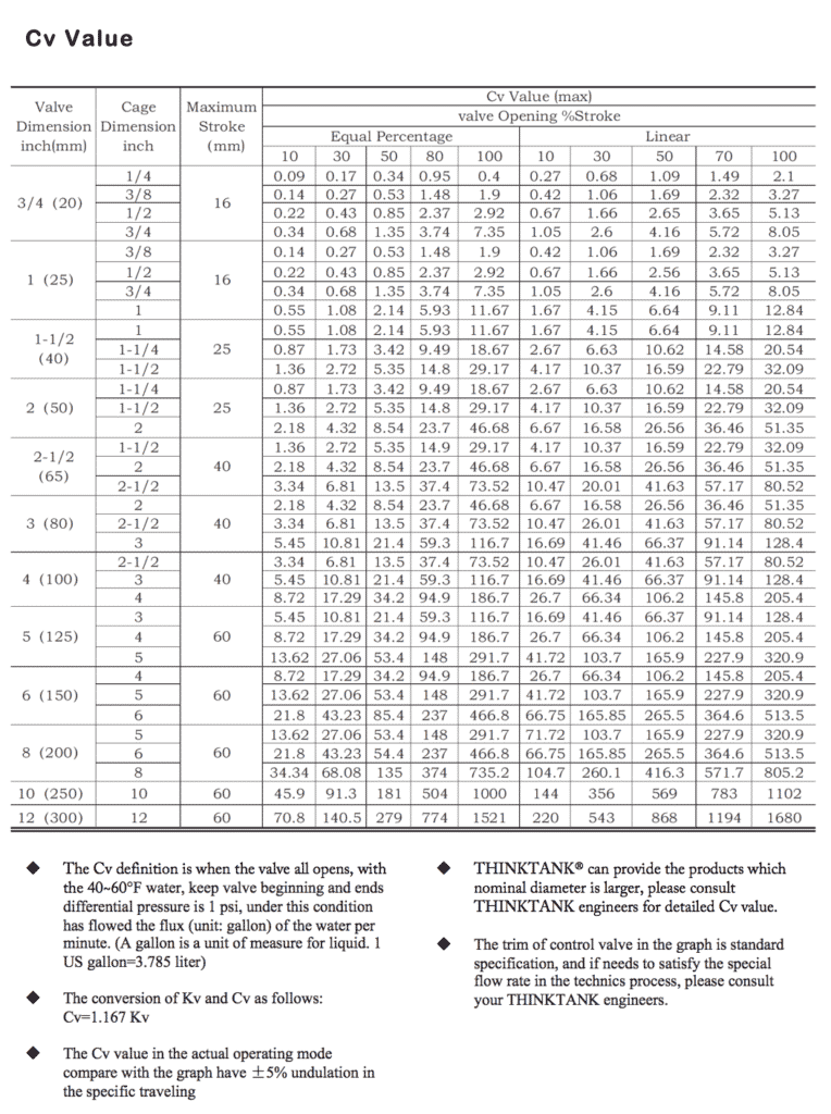
Step 6: Select the size of the valve based on the flow coefficient table and the determined Cv value.
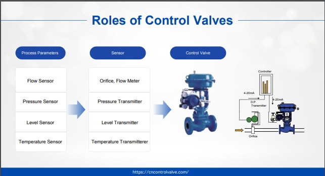
In the world of fluid control systems, proper control valve sizing is crucial to ensure efficient operation and optimal performance. Utilizing a well-calculated control valve sizing equation, engineers can accurately determine the appropriate dimensions for a control valve sizing calculation. This process involves a thorough control valve calculation that takes into account various factors such as fluid velocity, pressure differential, and maximum required flow rate. As a result, control valve selection becomes a more informed decision, with popular choices like Fisher control valve sizing and flow control valve sizing offering reliable solutions. Ultimately, a properly sized control valve will prevent issues associated with oversized control valves and enable seamless integration of control valves within a fluid control system.
In conclusion
Sizing a level control valve properly involves taking into account various parameters, such as the type of media being controlled, the required flow rate, pressure drops, etc., followed by selecting one that is best suited for your system’s needs while staying within its stated specifications. Properly sized valves can ensure effective performance from your liquid-level systems over time.