In engineering design, it is necessary to select and calculate the control valve to achieve the purpose of stable control. However, it is difficult to consider FL in the selection and calculation of the control valve. This article will analyze the general laws of FL, and at the same time analyze the possible blocking flow conditions through examples.
I. The Generation of Blocked Flow
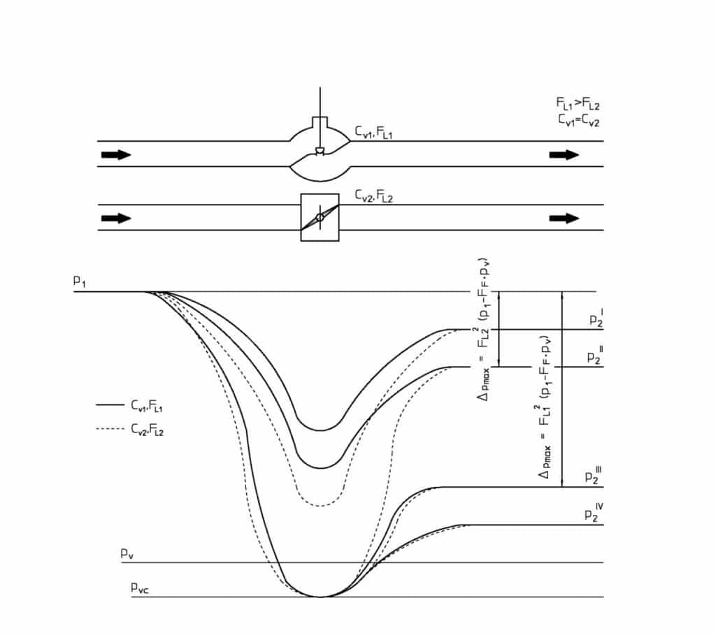
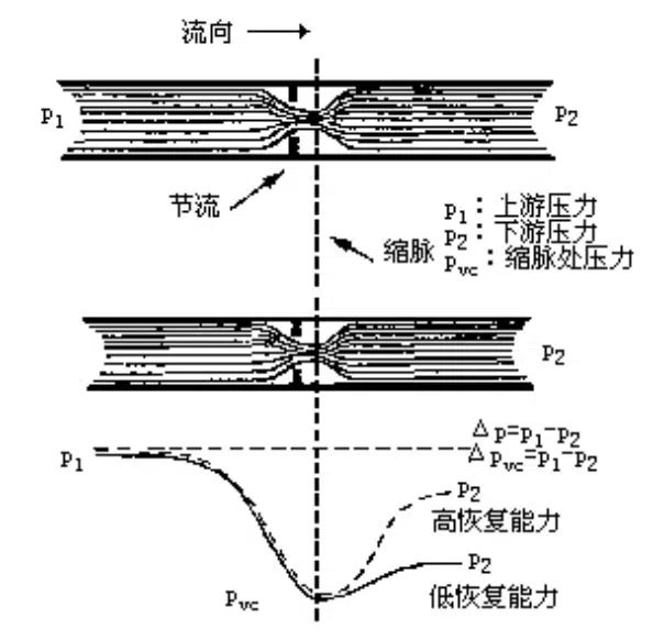
In the calculation formula of the flow coefficient Cv, the measuring pressure position of the inlet pressure P1, outlet pressure p2, pressure drop changes of the fluid passing through the control valve are shown in Figure 1.

The pressure drop on the valve ΔP=P1-P2. According to the law of conservation of energy, the flow velocity is the largest and the pressure is the lowest at the fluid contraction, so the pressure drop is the largest, which is called ΔPvc=P1-Pvc. After the contraction, the fluid velocity decreases again until most of the static pressure at P2 is restored, at which time the pressure drops to ΔP.
When the medium is a liquid, when the differential pressure is large enough, part of the liquid vaporizes at this operating temperature and flashing occurs. Steam is entrained in the liquid, resulting in a two-phase flow. The liquid is no longer incompressible. At this time, even if the differential pressure is increased, the flow rate will no longer increase. This limiting flow phenomenon is called liquid blocking flow.

II. Specific analysis of FL
a. Definition of FL
FL=Sqt(ΔPcr/ΔPvcr)=Sqt(P1-P2)/(P1-Pvc) (1)
In the formula, ΔPcr–valve pressure drop when blocking flow is generated, that is, the difference between the valve inlet pressure and the pressure of the contraction flow section when blocking flow, ΔPcr=(P1-P2)cr
b. The meaning of FL
FL is an experimental data that shows the recovery ability of the control valve to convert kinetic energy into static pressure energy after the liquid passes (see Figure 1), so it is called the pressure recovery coefficient, and it also shows the critical condition for the liquid to produce a blocked flow, also known as the critical condition. Flow Coefficient. The purpose of proposing FL is to determine whether a blocked flow occurs when the liquid passes through the control valve, and to calculate the maximum allowable pressure difference of the control valve.
c. Judgment of blocked flow
In theory, the relationship between the size of Pvc and Pv is used to determine whether a blocked flow is generated, but Pvc cannot be measured, so the differential pressure is used to judge in engineering calculations. Figure 2 shows the relationship between the flow through the control valve and the differential pressure.

The maximum allowable differential pressure is defined as ΔPvc, and its calculation formula is:
Δpc=FL2(P1-rcpv) (2)

Pv–liquid saturated vapor pressure at operating temperature;
Pc–the critical pressure of the liquid.
Once Δp is greater than Δpc, it indicates that the flow of liquid has been blocked.
d: Factors that determine blocked flow
From equation (2), once the operating conditions are determined, the maximum allowable differential pressure Δpc has a linear relationship with the square of FL. The generation of blocked flow has nothing to do with the size of the flow through the control valve and the diameter of the control valve.
III. The general rule of FL value
- The size of the FL value is related to the structure, flow direction and opening of the control valve. In general, the larger the valve opening, the smaller the FL value. The FL value provided by the manufacturer refers to the value when the control valve is fully opened. …
- The FL value of the control valve with exactly the same geometric structure is the same, and has nothing to do with the caliber. For the same type of control valve, the FL is slightly different due to the different structure of each manufacturer. …
- Internationally renowned manufacturers provide the FL value of each series of control valves, you can feel free to check the FL value as below sheet from THINKTANK control valves.
- The general relationship between FL value and control valve form and opening. In general, the FL value of a linear control valve is larger than that of a rotary control valve, and the FL value decreases as the opening of the control valve increases.
THINKTANK HCB Series Cv vs Travel Standard Trim (CAGE) Linear%
Size: 2 ” ~ 16″ Flow Characteristic: Linear Percentage Class: 150# ~ 600#
| Valve Travel [%] | 10 | 20 | 30 | 40 | 50 | 60 | 70 | 80 | 90 | 100 | ||||||||||||||||||||||||||||||||||
| FL | 0.94 | 0.94 | 0.93 | 0.93 | 0.92 | 0.92 | 0.91 | 0.91 | 0.90 | 0.90 | ||||||||||||||||||||||||||||||||||
| Valve Size | Orifice Dia. | Travel | Rated Cv | |||||||||||||||||||||||||||||||||||||||||
| Inch | mm | Sign | Inch | mm | Inch | mm | ||||||||||||||||||||||||||||||||||||||
| 2 | 50 | FC | 2.5 | 64.5 | 1.6 | 40 | 4.9 | 13.9 | 22.2 | 30.3 | 39.5 | 48.6 | 57.3 | 64.7 | 69.5 | 74 | ||||||||||||||||||||||||||||
| 1A | 3.5 | 7.6 | 12.5 | 17.3 | 22.4 | 27.6 | 33.1 | 38.5 | 43.6 | 48 | ||||||||||||||||||||||||||||||||||
| 2A | 2.6 | 5.2 | 7.7 | 10.3 | 12.9 | 15.4 | 18.0 | 20.6 | 23.2 | 26 | ||||||||||||||||||||||||||||||||||
| 3A | 1.6 | 3.2 | 4.8 | 6.3 | 7.9 | 9.5 | 11.1 | 12.7 | 14.3 | 16 | ||||||||||||||||||||||||||||||||||
| 3 | 80 | FC | 3.5 | 89.0 | 2.0 | 50 | 8.0 | 22.0 | 39.0 | 59.0 | 75.0 | 90.0 | 105.0 | 119.0 | 130.0 | 142 | ||||||||||||||||||||||||||||
| 1A | 6.2 | 16.6 | 26.9 | 36.9 | 46.6 | 56.8 | 67.4 | 78.0 | 87.8 | 98 | ||||||||||||||||||||||||||||||||||
| 2A | 4.5 | 11.1 | 16.6 | 22.2 | 27.7 | 33.3 | 38.8 | 44.4 | 49.9 | 56 | ||||||||||||||||||||||||||||||||||
| 3A | 3.4 | 6.7 | 10.1 | 13.5 | 16.8 | 20.2 | 23.6 | 26.9 | 30.3 | 34 | ||||||||||||||||||||||||||||||||||
| 4 | 100 | FC | 4.4 | 111.5 | 2.0 | 50 | 19.3 | 41.5 | 74.4 | 105.3 | 133.4 | 164.5 | 187.6 | 206.4 | 219.3 | 230 | ||||||||||||||||||||||||||||
| 1A | 8.0 | 25.4 | 43.1 | 60.4 | 77.2 | 93.8 | 110.7 | 127.6 | 143.9 | 160 | ||||||||||||||||||||||||||||||||||
| 2A | 6.0 | 17.0 | 25.5 | 34.1 | 42.6 | 51.1 | 59.6 | 68.1 | 76.6 | 86 | ||||||||||||||||||||||||||||||||||
| 3A | 5.2 | 10.3 | 15.4 | 20.6 | 25.7 | 30.9 | 36.0 | 41.2 | 46.3 | 52 | ||||||||||||||||||||||||||||||||||
| 6 | 150 | FC | 5.3 | 133.6 | 2.4 | 60 | 23.0 | 62.0 | 123.5 | 181.0 | 229.1 | 269.3 | 315.2 | 349.9 | 370.1 | 380 | ||||||||||||||||||||||||||||
| 1A | 12.0 | 40.9 | 71.4 | 101.4 | 130.6 | 158.9 | 186.7 | 214.7 | 242.2 | 275 | ||||||||||||||||||||||||||||||||||
| 2A | 9.5 | 29.7 | 44.6 | 59.4 | 74.3 | 89.1 | 104.0 | 118.8 | 133.7 | 150 | ||||||||||||||||||||||||||||||||||
| 3A | 8.0 | 17.8 | 26.7 | 35.6 | 44.6 | 53.5 | 62.4 | 71.3 | 80.2 | 90 | ||||||||||||||||||||||||||||||||||
| 8 | 200 | FC | 6.9 | 175.5 | 2.8 | 70 | 28.2 | 94.2 | 185.6 | 288.0 | 377.1 | 449.1 | 514.1 | 571.9 | 590.0 | 600 | ||||||||||||||||||||||||||||
| 1A | 14.5 | 52.5 | 108.0 | 172.0 | 232.0 | 299.0 | 365.0 | 417.0 | 430.0 | 455 | ||||||||||||||||||||||||||||||||||
| 2A | 10.0 | 45.0 | 75.4 | 100.6 | 125.7 | 150.9 | 176.0 | 201.2 | 226.3 | 254 | ||||||||||||||||||||||||||||||||||
| 3A | 9.0 | 30.1 | 45.1 | 60.2 | 75.2 | 90.3 | 105.3 | 120.4 | 135.4 | 152 | ||||||||||||||||||||||||||||||||||
| 10 | 250 | FC | 8.4 | 214.2 | 3.1 | 80 | 45.9 | 189.3 | 329.3 | 461.8 | 583.3 | 689.9 | 778.5 | 847.7 | 897.9 | 950 | ||||||||||||||||||||||||||||
| 1A | 25.0 | 103.6 | 183.3 | 260.7 | 337.5 | 414.1 | 489.4 | 562.3 | 631.5 | 700 | ||||||||||||||||||||||||||||||||||
| 2A | 17.0 | 78.8 | 118.2 | 157.6 | 197.0 | 236.4 | 275.8 | 315.2 | 354.6 | 398 | ||||||||||||||||||||||||||||||||||
| 3A | 12.0 | 46.7 | 70.1 | 93.5 | 116.8 | 140.2 | 163.6 | 186.9 | 210.3 | 238 | ||||||||||||||||||||||||||||||||||
| 12 | 300 | FC | 10.4 | 264.8 | 4.7 | 120 | 93.2 | 250.0 | 463.3 | 660.0 | 840.0 | 990.0 | 1115.0 | 1205.0 | 1250.0 | 1270 | ||||||||||||||||||||||||||||
| 1A | 66.7 | 167.8 | 276.8 | 382.9 | 485.5 | 586.9 | 692.1 | 796.9 | 893.0 | 970 | ||||||||||||||||||||||||||||||||||
| 2A | 25.0 | 108.9 | 163.4 | 218.0 | 272.3 | 326.7 | 381.2 | 435.6 | 490.1 | 550 | ||||||||||||||||||||||||||||||||||
| 3A | 17.0 | 67.3 | 101.0 | 134.6 | 168.3 | 202.0 | 235.6 | 269.3 | 302.9 | 340 | ||||||||||||||||||||||||||||||||||
| 14 | 350 | FC | 12.4 | 315.5 | 5.5 | 140 | 127.4 | 407.5 | 673.4 | 915.6 | 1128.5 | 1316.5 | 1474.2 | 1593.1 | 1671.4 | 1740 | ||||||||||||||||||||||||||||
| 1A | 91.3 | 233.3 | 393.0 | 548.1 | 696.8 | 838.0 | 976.4 | 1105.4 | 1221.2 | 1300 | ||||||||||||||||||||||||||||||||||
| 2A | 52.0 | 153.7 | 230.5 | 307.3 | 384.1 | 460.9 | 537.8 | 614.6 | 691.4 | 776 | ||||||||||||||||||||||||||||||||||
| 3A | 27.0 | 91.9 | 137.8 | 183.7 | 229.7 | 275.6 | 321.6 | 367.5 | 413.4 | 464 | ||||||||||||||||||||||||||||||||||
| 16 | 400 | FC | 14.1 | 357.7 | 6.3 | 160 | 189.0 | 497.0 | 891.8 | 1248.0 | 1535.4 | 1791.5 | 1950.0 | 2063.0 | 2161.6 | 2215 | ||||||||||||||||||||||||||||
| 1A | 101.3 | 276.5 | 448.1 | 615.0 | 779.1 | 941.9 | 1101.6 | 1255.7 | 1398.9 | 1530 | ||||||||||||||||||||||||||||||||||
| 2A | 71.0 | 186.1 | 279.2 | 372.2 | 465.3 | 558.4 | 651.4 | 744.5 | 837.5 | 940 | ||||||||||||||||||||||||||||||||||
| 3A | 47.0 | 112.5 | 168.7 | 224.9 | 281.2 | 337.4 | 393.6 | 449.9 | 506.1 | 568 | ||||||||||||||||||||||||||||||||||
NOTE
Cv: Valve flow coefficient
FL: Liquid pressure recovery factor
FC: Full Capacity 1A: 1-Step reduction
2A: 2-Step reduction 3A: 3-Step reduction
THINKTANK HCB Series Cv vs Travel Standard Trim (CAGE) EQ%
Size: 2 ” ~ 16″ Flow Characteristic: Equal Percentage Class: 150# ~ 600#
| Valve Travel [%] | 10 | 20 | 30 | 40 | 50 | 60 | 70 | 80 | 90 | 100 | ||||||||||||||||||||||||||||||||||
| FL | 0.94 | 0.94 | 0.93 | 0.93 | 0.92 | 0.92 | 0.91 | 0.91 | 0.90 | 0.90 | ||||||||||||||||||||||||||||||||||
| Valve Size | Orifice Dia. | Travel | Rated Cv | |||||||||||||||||||||||||||||||||||||||||
| Inch | mm | Sign | Inch | mm | Inch | mm | ||||||||||||||||||||||||||||||||||||||
| 2 | 50 | FC | 2.5 | 64.5 | 1.6 | 40 | 2.00 | 4.00 | 6.00 | 9.00 | 14.00 | 21.00 | 33.00 | 50.00 | 66.00 | 71 | ||||||||||||||||||||||||||||
| 1A | 1.07 | 3.28 | 5.45 | 7.57 | 9.75 | 12.79 | 17.86 | 26.28 | 39.68 | 50 | ||||||||||||||||||||||||||||||||||
| 2A | 0.59 | 1.19 | 1.60 | 2.48 | 4.57 | 8.16 | 12.88 | 17.74 | 21.59 | 24 | ||||||||||||||||||||||||||||||||||
| 3A | 0.34 | 0.70 | 0.94 | 1.45 | 2.67 | 4.76 | 7.51 | 10.35 | 12.59 | 14 | ||||||||||||||||||||||||||||||||||
| 3 | 80 | FC | 3.5 | 89.0 | 2.0 | 50 | 4.00 | 8.50 | 14.50 | 22.00 | 33.50 | 51.00 | 75.00 | 108.00 | 128.00 | 138 | ||||||||||||||||||||||||||||
| 1A | 2.50 | 3.72 | 6.61 | 11.10 | 18.35 | 29.43 | 45.56 | 67.65 | 91.99 | 110 | ||||||||||||||||||||||||||||||||||
| 2A | 1.22 | 2.48 | 3.34 | 5.17 | 9.52 | 17.00 | 26.82 | 36.97 | 44.98 | 50 | ||||||||||||||||||||||||||||||||||
| 3A | 0.78 | 1.59 | 2.14 | 3.31 | 6.09 | 10.88 | 17.17 | 23.66 | 28.79 | 32 | ||||||||||||||||||||||||||||||||||
| 4 | 100 | FC | 4.4 | 111.5 | 2.0 | 50 | 5.60 | 12.90 | 23.40 | 36.90 | 59.60 | 86.50 | 128.20 | 163.90 | 188.60 | 210 | ||||||||||||||||||||||||||||
| 1A | 2.75 | 6.68 | 11.68 | 17.92 | 28.59 | 46.21 | 71.85 | 105.81 | 141.21 | 160 | ||||||||||||||||||||||||||||||||||
| 2A | 2.00 | 4.07 | 5.48 | 8.48 | 15.61 | 27.88 | 43.99 | 60.62 | 73.76 | 82 | ||||||||||||||||||||||||||||||||||
| 3A | 1.22 | 2.48 | 3.34 | 5.17 | 9.52 | 17.00 | 26.82 | 36.97 | 44.98 | 50 | ||||||||||||||||||||||||||||||||||
| 6 | 150 | FC | 5.3 | 133.6 | 2.4 | 60 | 6.50 | 15.00 | 27.70 | 47.10 | 77.10 | 123.80 | 198.50 | 265.20 | 316.00 | 340 | ||||||||||||||||||||||||||||
| 1A | 3.40 | 11.12 | 22.00 | 32.25 | 50.35 | 81.67 | 126.81 | 187.40 | 246.30 | 270 | ||||||||||||||||||||||||||||||||||
| 2A | 3.32 | 6.76 | 9.08 | 14.06 | 25.89 | 46.24 | 72.95 | 100.54 | 122.34 | 136 | ||||||||||||||||||||||||||||||||||
| 3A | 2.00 | 4.07 | 5.48 | 8.48 | 15.61 | 27.88 | 43.99 | 60.62 | 73.76 | 82 | ||||||||||||||||||||||||||||||||||
| 8 | 200 | FC | 6.9 | 175.5 | 2.8 | 70 | 6.50 | 23.00 | 45.00 | 83.00 | 138.00 | 220.00 | 325.00 | 445.00 | 510.00 | 560 | ||||||||||||||||||||||||||||
| 1A | 5.60 | 19.00 | 39.00 | 58.00 | 94.00 | 148.00 | 222.00 | 310.00 | 405.00 | 450 | ||||||||||||||||||||||||||||||||||
| 2A | 4.00 | 11.72 | 15.76 | 24.39 | 44.92 | 80.23 | 126.59 | 174.47 | 212.29 | 236 | ||||||||||||||||||||||||||||||||||
| 3A | 3.00 | 7.05 | 9.48 | 14.68 | 27.03 | 48.27 | 76.17 | 104.98 | 127.73 | 142 | ||||||||||||||||||||||||||||||||||
| 10 | 250 | FC | 8.4 | 214.2 | 3.1 | 80 | 8.10 | 33.20 | 65.70 | 124.40 | 216.80 | 350.10 | 493.20 | 619.90 | 747.60 | 830 | ||||||||||||||||||||||||||||
| 1A | 6.52 | 26.50 | 47.14 | 76.22 | 126.33 | 219.81 | 343.21 | 460.04 | 566.24 | 655 | ||||||||||||||||||||||||||||||||||
| 2A | 6.13 | 18.58 | 24.97 | 38.66 | 71.19 | 127.15 | 200.62 | 276.49 | 336.42 | 374 | ||||||||||||||||||||||||||||||||||
| 3A | 5.47 | 11.13 | 14.96 | 23.15 | 42.64 | 76.15 | 120.16 | 165.60 | 201.50 | 224 | ||||||||||||||||||||||||||||||||||
| 12 | 300 | FC | 10.4 | 264.8 | 4.7 | 120 | 22.40 | 64.30 | 111.10 | 179.80 | 303.10 | 546.80 | 795.00 | 996.00 | 1155.00 | 1240 | ||||||||||||||||||||||||||||
| 1A | 15.54 | 44.65 | 73.67 | 110.47 | 174.20 | 277.57 | 441.34 | 650.51 | 837.52 | 960 | ||||||||||||||||||||||||||||||||||
| 2A | 12.79 | 26.03 | 34.99 | 54.16 | 99.74 | 178.14 | 281.08 | 387.39 | 471.35 | 524 | ||||||||||||||||||||||||||||||||||
| 3A | 7.67 | 15.60 | 20.97 | 32.45 | 59.77 | 106.75 | 168.43 | 232.14 | 282.45 | 314 | ||||||||||||||||||||||||||||||||||
| 14 | 350 | FC | 12.4 | 315.5 | 5.5 | 140 | 24.70 | 82.30 | 158.30 | 266.70 | 427.00 | 693.90 | 1015.80 | 1277.20 | 1514.70 | 1650 | ||||||||||||||||||||||||||||
| 1A | 18.94 | 60.21 | 103.15 | 164.81 | 260.61 | 405.54 | 630.90 | 903.93 | 1141.45 | 1275 | ||||||||||||||||||||||||||||||||||
| 2A | 16.21 | 37.06 | 49.81 | 77.10 | 142.00 | 253.61 | 400.17 | 551.51 | 671.05 | 746 | ||||||||||||||||||||||||||||||||||
| 3A | 10.89 | 22.16 | 29.78 | 46.10 | 84.89 | 151.62 | 239.24 | 329.72 | 401.19 | 446 | ||||||||||||||||||||||||||||||||||
| 16 | 400 | FC | 14.1 | 357.7 | 6.3 | 160 | 35.10 | 100.40 | 167.00 | 268.40 | 471.00 | 849.30 | 1265.10 | 1603.90 | 1911.60 | 2090 | ||||||||||||||||||||||||||||
| 1A | 26.32 | 73.03 | 119.55 | 175.70 | 286.98 | 477.71 | 773.09 | 1125.40 | 1432.44 | 1680 | ||||||||||||||||||||||||||||||||||
| 2A | 20.85 | 42.42 | 57.03 | 88.27 | 162.55 | 290.33 | 458.10 | 631.35 | 768.20 | 854 | ||||||||||||||||||||||||||||||||||
| 3A | 12.50 | 25.43 | 34.19 | 52.92 | 97.46 | 174.06 | 274.65 | 378.52 | 460.56 | 512 | ||||||||||||||||||||||||||||||||||
NOTE
Cv: Valve flow coefficient
FL: Liquid pressure recovery factor
FC: Full Capacity 1A: 1-Step reduction
2A: 2-Step reduction 3A: 3-Step reduction
IV. The consideration of FL value in engineering design
- There are not many cases of blocked flow encountered in engineering design. Sometimes the process requires blocked flow, such as liquid phase change and gas phase as refrigerant. However, in most operating conditions, it is desirable to avoid blocking the flow.
- To avoid blocking the flow, a control valve with a larger value can be selected, so that Δpc is also correspondingly large. Choosing a large diameter does not avoid blocking the flow.
- The FL of the single-seat valve is larger than that of the rotary valve. For the large-diameter rotary valve, the correction of the FL value by the size of the pipe should be considered.
- When the manufacturer does not provide the FL value of the control valve, the FL value listed in above sheets can be used as an estimation reference.
- Dynamic correction of FL when the valve opens at different degrees. Since the calculation of the control valve Cv value only considers a certain point of the operating conditions, it cannot guarantee that all operating conditions will avoid blocked flow, so when calculating Δpc, it is necessary to analyze it from a dynamic perspective.
- When estimating, the FL value can be the smallest value in the entire opening, which is generally the FL value in the product manual. The pressure p1 in front of the valve generally decreases (or is constant) with the increase of the opening, so it is safer to use the p1 under the maximum flow to calculate ΔPc.
- If it is found that FL and p1 do not conform to the above rules during the calculation of the control valve, Δpc shall be checked for the selected control valve at the operating point required by each process to check whether there is a possibility of blocking the flow.
V. Conclusion
There are many ways to deal with the blocked flow in the project, such as cage type control valves, multi-stage pressure reduction, installing orifice plate at the downstream of valves, etc., but the purpose is to increase the Pvc to avoid blocked flow. It is the simplest and most convenient method to choose a control valve with a larger FL value.


