This guide explains how to configure and automatically calibrate a Metso Neles ND9000 intelligent valve controller using the local keypad.
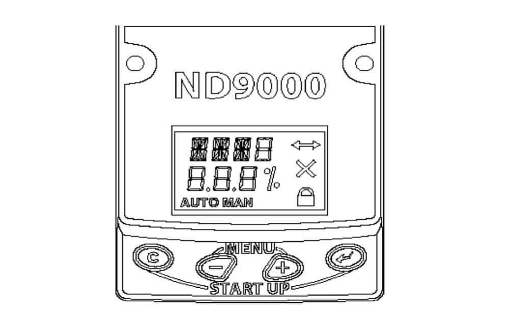
Key Functions
| Key | Function |
|---|---|
| C | Cancel or return to the previous menu |
| + / − | Scroll through menus or change a setting |
| Enter | Open a setting or confirm the selected value |
Before Calibration
Make sure that:
- The positioner is correctly mounted.
- The pneumatic tubing is correctly connected.
- The supply air pressure is available.
- The 4–20 mA signal or fieldbus power is connected.
- The valve can safely move through its full travel.
Warning: Automatic calibration drives the valve to its fully open and fully closed mechanical limits. Do not start calibration while the valve is controlling an active process.
ND9000 Configuration and Auto Calibration
| Step | Procedure |
|---|---|
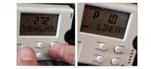
| 1. Enter Guided Start-up | From the normal measurement display, press the C and Enter keys simultaneously. The display will show VTYP. |
| 2. Select Valve Type – VTYP | Press Enter until the value flashes. Use + / − to select the valve type: rot for rotary valves or LIn for linear valves. Press Enter to confirm. |
| 3. Select Actuator Type – ATYP | Use + / − to find ATYP, then press Enter. Select 2-A for a double-acting actuator or 1-A for a single-acting actuator. Press Enter to confirm. |
| 4. Set Positioner Fail Action – PFA | Select PFA and press Enter. Choose CLO if the valve must close on signal or internal positioner failure, or OPE if the valve must open. For a single-acting actuator, this setting must match the actuator spring direction. |
| 5. Set Valve Rotation – ROT | Select ROT and press Enter. Choose cC if clockwise rotation closes the valve, or ccC if counterclockwise rotation closes the valve. Press Enter to confirm. |
| 6. Set Valve Dead Angle – A0 | Select A0 and press Enter. Set the required dead-angle compensation using + / −, then press Enter. For valves that do not require dead-angle compensation, use 0%. |
| 7. Select Calibration – CAL | Use + / − to find CAL, then press Enter. |
| 8. Start Auto Calibration | Select AUTO and press Enter. The display flashes CAL, and the calibration progress increases from 1 to 100. |
| 9. Confirm Completion | Wait until the display shows POSITION CALIBRATION SUCCESSFUL. Press C to return to the normal measurement display. |
| 10. Verify Valve Operation | Apply several input signals, such as 0%, 25%, 50%, 75% and 100%. Confirm that the valve moves in the correct direction and reaches the required positions. |
The guided start-up sequence follows VTYP → ATYP → PFA → ROT → A0 → CAL. Changing any of these critical parameters requires the valve controller to be recalibrated.
Valve Type Settings
| Setting | Application |
|---|---|
| rot | Rotary valves, including ball valves, butterfly valves and segment valves |
| LIn | Standard linear control valves |
| nCG | Neles globe valves with special linkage geometry |
| FLI | Linear valves requiring feedback-linkage correction |
For normal third-party globe control valves, LIn is usually selected. The special nCG and FLI settings should only be used when required by the valve and linkage arrangement.
Positioner Fail Action
| Setting | Valve Action |
|---|---|
| CLO | Valve moves toward the closed position during signal failure or a fatal controller fault |
| OPE | Valve moves toward the open position during signal failure or a fatal controller fault |
For a spring-return actuator, PFA must correspond to the actuator spring direction:
- Spring-to-close actuator: select CLO
- Spring-to-open actuator: select OPE
For double-acting actuators, confirm the pneumatic connections before selecting the fail action.
Valve Rotation Direction
The ROT setting describes the rotation direction required to close the valve:
- cC: Clockwise rotation closes the valve
- ccC: Counterclockwise rotation closes the valve
Always check the actual valve stem or shaft movement instead of selecting the setting only from the actuator nameplate.
A0 Dead-Angle Setting
The A0 parameter compensates for the mechanical dead angle of certain Neles ball valves, V-port ball valves and segment valves.
It is not a general valve travel setting.
For valves that do not require this compensation, set:
A0 = 0%
For applicable Neles valves, use the value specified for the valve model and size in the manufacturer’s dead-angle table.
AUTO and MAN Mode
To change the operating mode:
- Press + and − simultaneously.
- Select MODE.
- Press Enter.
- Select AUTO or MAN.
- Press Enter to confirm.
| Mode | Function |
|---|---|
| AUTO | The positioner follows the incoming 4–20 mA or fieldbus setpoint |
| MAN | The valve position is controlled manually using the local + / − keys |
The controller must be in AUTO mode before running normal automatic travel calibration. In MAN mode, the valve does not follow the external control signal.
When Manual Calibration Is Required
Use manual calibration when:
- The valve cannot safely travel to the fully open position.
- The valve does not have a mechanical open limit stop.
- Automatic calibration is unavailable.
- The valve travel must be restricted during commissioning.
Automatic calibration is normally the preferred method when the valve can safely complete its full stroke.
Quick Setup Sequence
For most rotary control valves:
C + Enter → VTYP: rot → ATYP → PFA → ROT → A0 → CAL: AUTO
For most linear control valves:
C + Enter → VTYP: LIn → ATYP → PFA → ROT → A0: 0% → CAL: AUTO
After calibration, verify positioner error and deadband against the project’s calibration criteria rather than relying only on completion of the full-stroke routine.