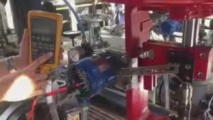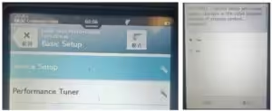
This guide explains the basic setup and automatic calibration procedure for a Fisher FOUNDATION Fieldbus valve positioner using a handheld communicator.
Before starting, confirm that the positioner, actuator, feedback mechanism, air supply, and fieldbus wiring are installed correctly.
Step by Step For Fisher Fieldbus Valve Positioner Automatic Calibration
Step 1: Connect the Communicator and Enter Fieldbus
Connect the handheld communicator to the Fisher positioner.
After the device connection screen appears, select the field communicator option and then select:
Fieldbus
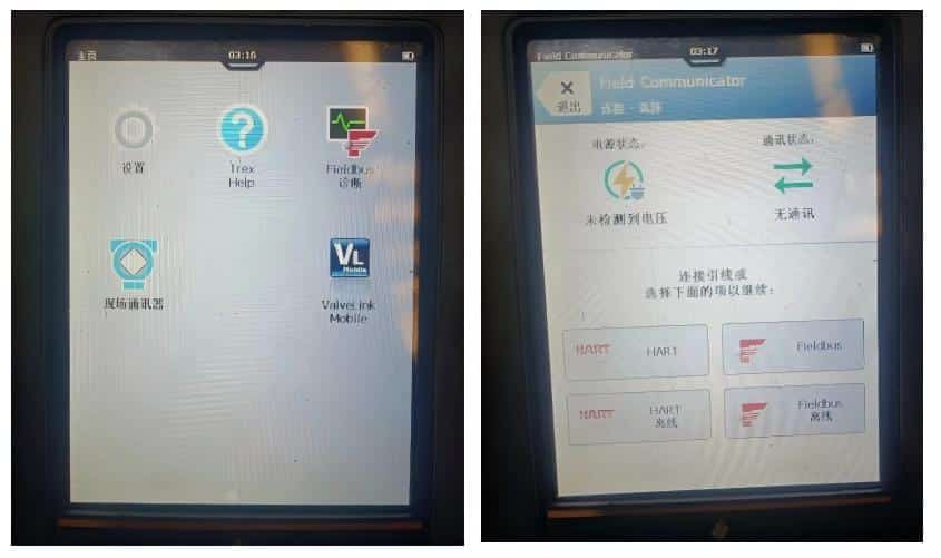
Step 2: Change the Device Address
When prompted, select Yes to enter the device list.
If the device address is displayed as 250, change it to an address between:
25 and 30
When the device address has already been correctly configured, this step may be skipped.
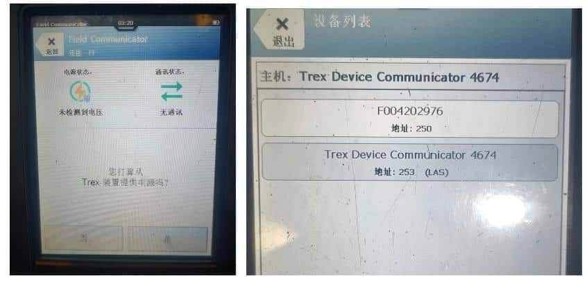
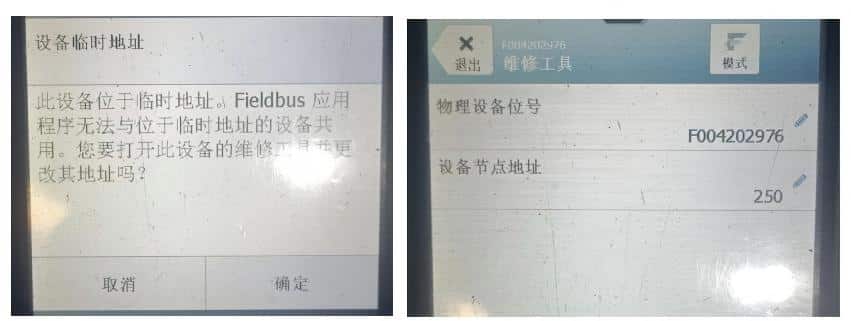
Step 3: Confirm the Temporary Device Address
Enter the Temporary Device Address option and select OK.
Set the device node address to a value between:
25 and 30
Confirm the new address.
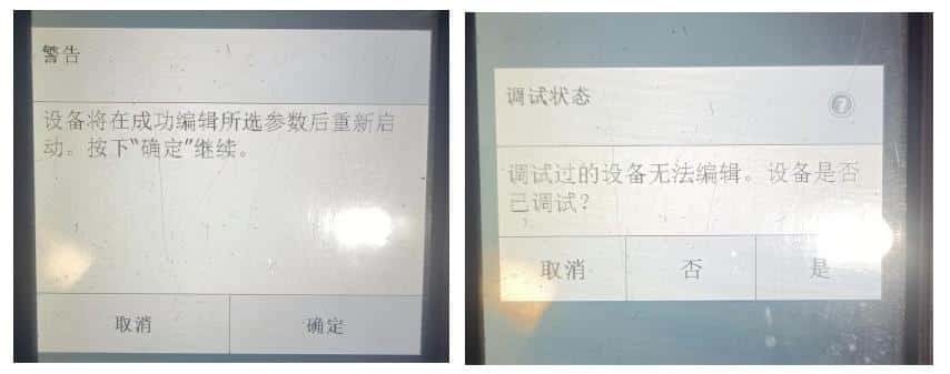
Step 4: Select the Device Commissioning Status
A warning message will appear after changing the device data.
Select Confirm to continue.
When the communicator asks whether the device has already been commissioned, select:
No
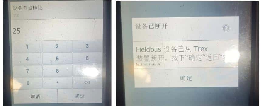
Step 5: Confirm the Device Node Address Again
Check that the device node address is set between 25 and 30, and then select Confirm.
When the device-disconnected message appears, select Confirm again.
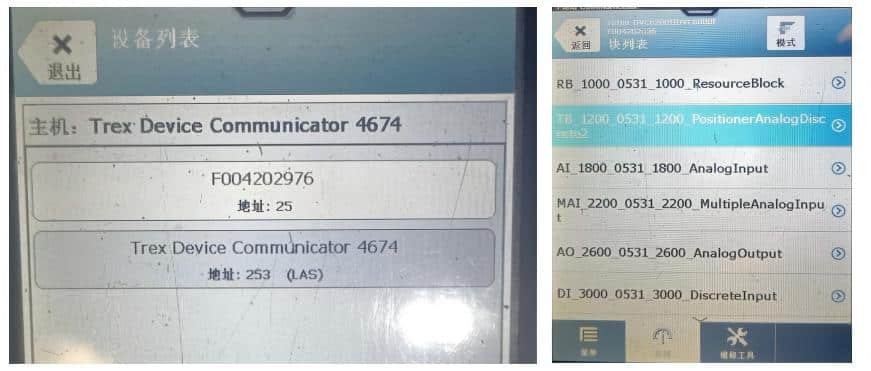
Step 6: Open the TB 1200 Block
After confirmation, the communicator will return to the device list.
Wait approximately three seconds for the device address to refresh.
Select the corresponding device identification number, such as:
F004202976
Enter the block list and select:
TB 1200
The identification number shown on each device may be different.
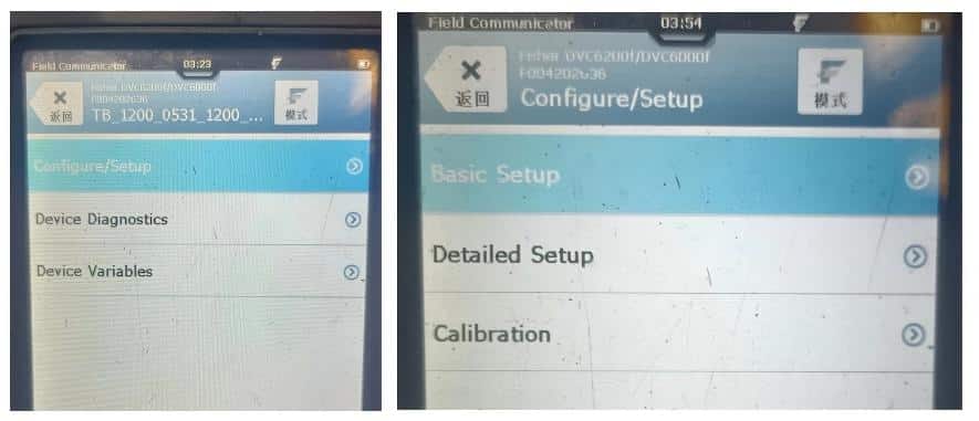
Step 7: Enter Basic Setup
In the TB 1200 menu, select:
Configure/Setup
Then select:
Basic Setup
Step 8: Start Device Setup
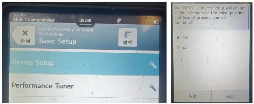
In the Basic Setup menu, select:
Device Setup
When the confirmation message appears, select:
Yes
Then select Confirm.
Step 9: Select the Relay Type and Control Mode
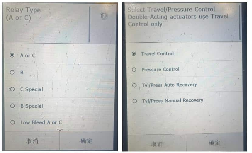
In the Relay Type menu, select:
A or C
Select the correct relay type according to the actual positioner configuration.
Then select:
Travel Control
Confirm the selection to continue.
Step 10: Configure the Pressure Unit and Valve Manufacturer
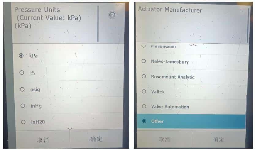
Select the required air-supply pressure unit. In this procedure, select:
kPa
On the valve manufacturer screen, scroll down and select:
Other
Select Other when the actual valve manufacturer is not included in the available manufacturer list.
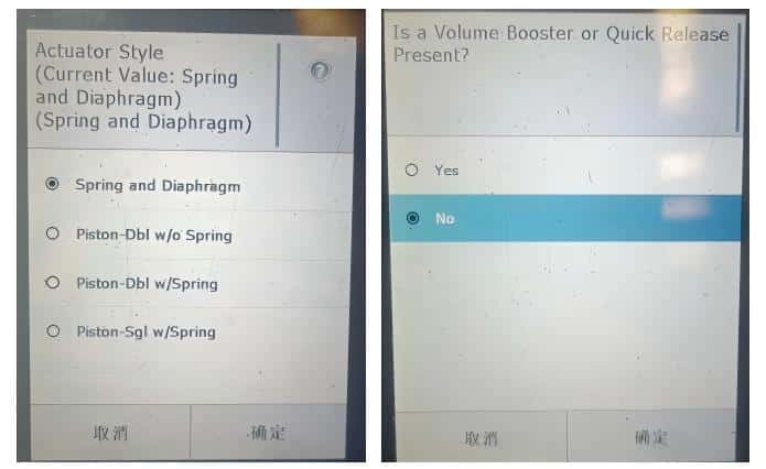
Step 11: Select the Actuator Type
Select the actuator type according to the actual valve assembly.
For a spring-and-diaphragm actuator, select:
Spring and Diaphragm
When the following confirmation screen appears, select:
No
The actuator option must always match the actual actuator installed on the valve.
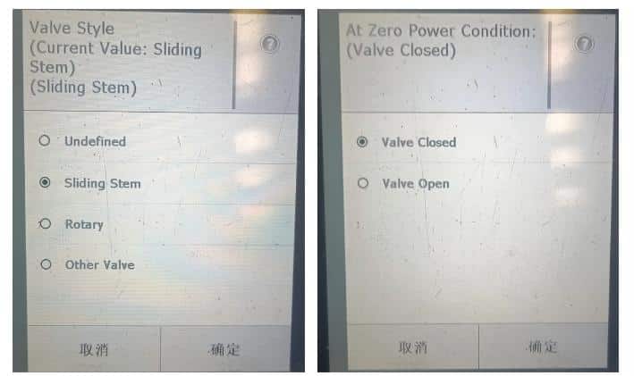
Step 12: Configure the Valve Type and Fail Position
For a linear control valve, select:
Sliding Stem
Then select the valve position according to the actuator action:
- For an air-to-open valve, select Valve Closed.
- For an air-to-close valve, select Valve Open.
Confirm the selection.
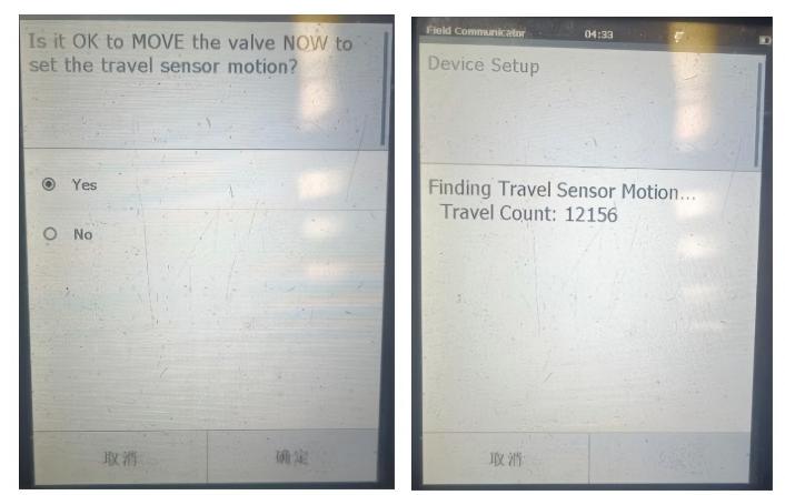
Step 13: Start the Initial Setup
When prompted to continue, select:
Yes
Then select Confirm.
The positioner will begin the setup process. Do not operate the valve, interrupt the air supply, or disconnect the fieldbus communication during this procedure.
Wait until the setup process is completed.
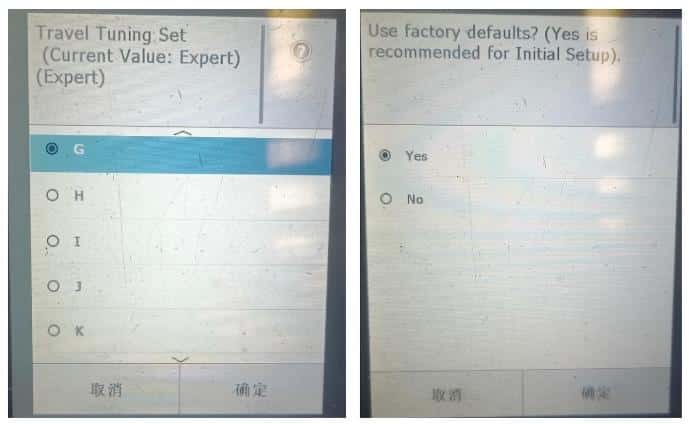
Step 14: Set the Tuning Sensitivity
After the initial setup, the communicator will display the tuning or gain selection.
For a typical workshop setup, gain level:
G
may be selected.
The appropriate gain level should be selected according to the valve size, actuator volume, and actual valve response.
After selecting the gain level, select:
Yes
Then confirm the setting.
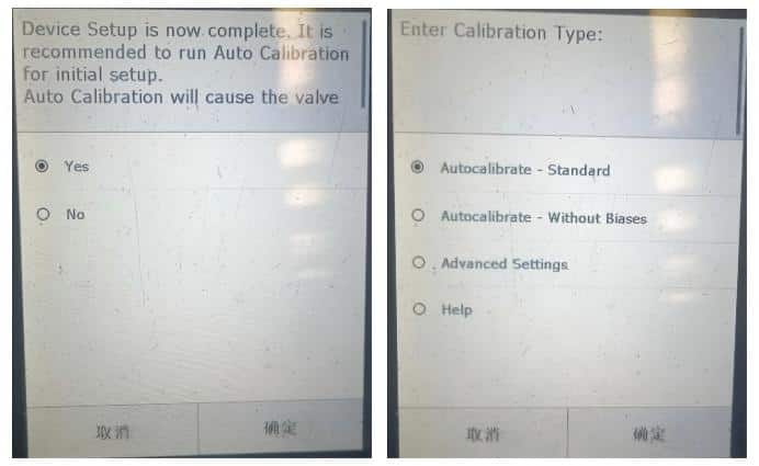
Step 15: Run Automatic Calibration
When the next confirmation screen appears, select:
Yes
Then select:
Autocalibrate – Standard
Confirm the selection to start automatic calibration.
The positioner will automatically move the valve through its travel and determine the required calibration parameters.
Keep clear of the valve stem and all other moving parts.
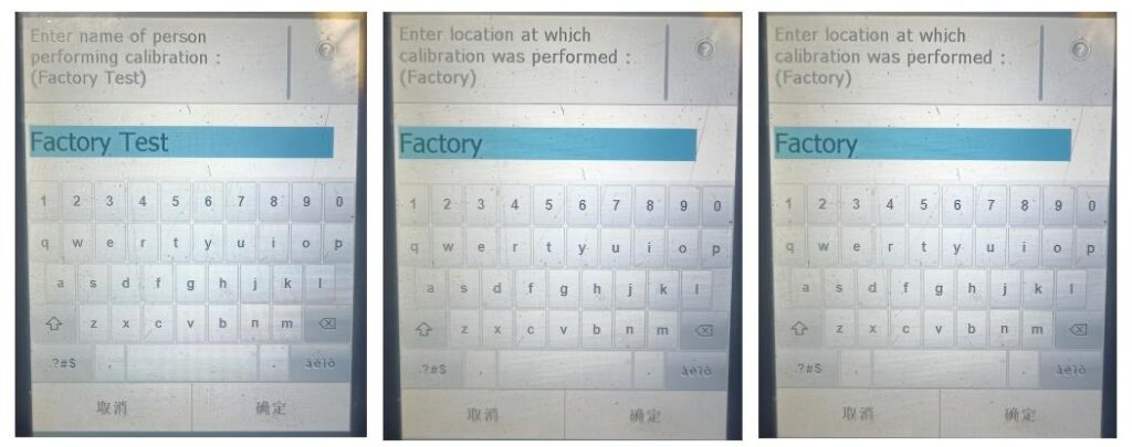
Step 16: Confirm the Calibration Results
After automatic calibration is completed, several confirmation messages may appear.
Select OK or Confirm on each screen to continue.
Check that no calibration error or travel warning is displayed.
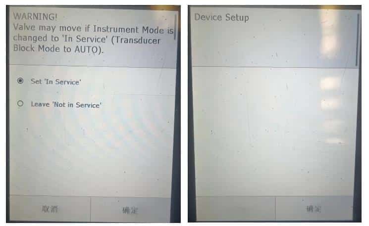
Step 17: Set the Positioner In Service
When the operating-status menu appears, select:
Set In Service
Confirm the selection.
When the final confirmation screen appears, select OK.
The Fisher fieldbus positioner commissioning and automatic calibration procedure is now complete.
Important Note
A FOUNDATION Fieldbus positioner cannot normally be controlled by changing the output of a conventional 4–20 mA signal generator.
To manually change the valve opening during testing, use the relevant fieldbus configuration or commissioning software and place the control block in MAN — Manual Mode. The valve position can then be adjusted through the manual output command.
Final Functional Check
After commissioning, confirm that:
- The device address is correctly configured.
- The positioner is set In Service.
- The relay and actuator types are correct.
- The configured valve action matches the actual actuator action.
- The valve reaches its fully open and fully closed positions.
- The actual valve position follows the fieldbus command.
- The valve moves smoothly without hunting or excessive overshoot.
- No device, travel, or calibration alarms are active.
Need Support with Control Valve Selection or Replacement?
THINKTANK is a professional control valve manufacturer with more than 30 years of industry experience.
In addition to valve positioner setup and troubleshooting support, our engineering team can help you select complete control valve assemblies based on the actual process conditions, including the valve body, trim, actuator, positioner, and accessories.
If you are looking for an alternative to an existing ABB, Fisher, Masoneilan, Flowserve, Samson, or other branded control valve, please send us the valve nameplate, datasheet, operating conditions, or current model number.
We can review the original valve specification and provide a technically compatible replacement solution with reliable performance, shorter delivery time, and a more competitive total cost.
Contact THINKTANK for control valve selection, troubleshooting, or replacement support.