This engineering guide explains 27 commonly used pneumatic control circuits for single-acting and double-acting valve actuators, including loss-of-air, loss-of-power, loss-of-signal, fast-stroking, anti-surge, turbine bypass, safety shut-off, and time-delay functions.
Introduction
A pneumatic actuator does not determine a control valve’s failure behavior by itself. The final action of the valve depends on the complete pneumatic circuit: actuator type, spring direction, positioner, solenoid valve, pressure-sensing trip valve, pneumatic lock-up valve, volume booster, pilot-operated directional valve, quick exhaust valve, check valve, air receiver, tubing, and the way these devices are connected.
This guide explains 27 representative pneumatic control circuits. The circuits are grouped into four families:
- Single-acting actuator circuits
- Double-acting actuator circuits
- Two-stage actuator circuits
- Special-purpose circuits for anti-surge valves, steam vent valves, turbine bypass valves, safety shut-off valves, and delayed fail action
Each circuit is explained in the same order:
- intended function;
- normal operating mode;
- response to loss of instrument air, electrical power, or control signal;
- function of the principal accessories; and
- engineering points that must be verified before manufacturing or commissioning.
These diagrams are functional examples, not universal hook-up drawings. Port numbering, normal valve position, pilot logic, exhaust routing, electrical certification, and accessory flow capacity vary by manufacturer and project specification. The final pneumatic schematic must therefore be checked against the selected products’ data sheets and the project’s cause-and-effect matrix.
Terminology Used in This Guide
Fail-Safe Return
The valve moves to its specified failure position after a defined fault. Depending on the process requirement and actuator orientation, that position may be fail-closed, fail-open, fail-up, fail-down, fail-clockwise, or fail-counterclockwise.
The Chinese source uses the word “reset” in several titles. In this article, “fail-safe return” is used because it describes the engineering function more accurately and avoids confusion with manual or automatic device reset.
Fail-in-Place
The pneumatic lock-up device isolates the actuator chamber or chambers so the valve remains near its last position. This is not an unlimited mechanical lock. The duration and accuracy of the held position depend on internal and external leakage, actuator seals, tubing, fittings, temperature, process forces, and the pressure trapped at the moment of failure.
Loss of Air, Power, and Signal
- Loss of air: the instrument-air pressure falls below an adjusted trip point or is completely lost.
- Loss of power: the solenoid valve is de-energized.
- Loss of signal: the 4-20 mA control signal falls below the configured detection threshold or is interrupted.
- Three-failure protection: the circuit responds to loss of air, loss of solenoid power, or loss of the control signal.
Pressure-Sensing Trip Valve and Pneumatic Lock-Up Valve
A pressure-sensing trip valve changes pneumatic flow paths when supply pressure drops below its set point. Depending on its internal arrangement and external connections, it can initiate fail-up, fail-down, fail-open, fail-close, or another defined action.
A pneumatic lock-up valve shuts off the actuator signal-pressure path and traps pressure in the actuator. It is used for fail-in-place service. The two devices must not be treated as interchangeable merely because both respond to low supply pressure.
High-Capacity Version
Several source diagrams are described as “large-diameter valve” circuits. Valve nominal size alone does not determine the pneumatic arrangement. In this guide, “high-capacity version” means that actuator volume, tubing losses, or the specified stroking time requires a volume booster, a higher-flow pilot valve, larger tubing, or a combination of these.
Quick Selection Map
| No. | Actuator and Service | Required Failure or Special Action |
| 1 | Single-acting, modulating | Loss of air or power: fail-safe return |
| 2 | Single-acting, on-off | Loss of air or power: fail-safe return |
| 3 | Single-acting, on-off, high-capacity | Loss of air or power: rapid fail-safe return |
| 4 | Single-acting, modulating, high-capacity | Loss of air or power: rapid fail-safe return |
| 5 | Single-acting, on-off | Loss of air: fail-in-place |
| 6 | Single-acting, modulating | Loss of air or power: fail-in-place |
| 7 | Single-acting, on-off, high-capacity | Loss of air: fail-in-place |
| 8 | Single-acting, modulating, high-capacity | Loss of air or power: fail-in-place |
| 9 | Single-acting, modulating | Loss of air, power, or signal: fail-in-place |
| 10 | Single-acting, modulating, high-capacity | Loss of air, power, or signal: fail-in-place |
| 11 | Double-acting, on-off | Loss of air or power: stored-air fail-safe return |
| 12 | Double-acting, on-off, high-capacity | Loss of air or power: rapid stored-air fail-safe return |
| 13 | Double-acting, modulating | Loss of air or power: stored-air fail-safe return |
| 14 | Double-acting, modulating, high-capacity | Loss of air or power: rapid stored-air fail-safe return |
| 15 | Double-acting, on-off | Loss of air: fail-in-place |
| 16 | Double-acting, modulating | Loss of air or power: fail-in-place |
| 17 | Double-acting, on-off, high-capacity | Loss of air: fail-in-place |
| 18 | Double-acting, modulating, high-capacity | Loss of air or power: fail-in-place |
| 19 | Double-acting, modulating | Loss of air, power, or signal: fail-in-place |
| 20 | Double-acting, modulating, high-capacity | Loss of air, power, or signal: fail-in-place |
| 21 | Two-stage actuator | Three discrete positions with two solenoid valves |
| 22 | Double-acting two-stage actuator | Three discrete positions with two solenoid valves |
| 23 | Compressor anti-surge valve | Controlled modulation and fast emergency opening |
| 24 | Steam vent valve | Modulation and stored-air closing on supply failure |
| 25 | Turbine bypass valve | Multi-level command priority, rapid close, and rapid open |
| 26 | Self-actuated safety shut-off valve | Remote and local overpressure trip with manual reset |
| 27 | Single-acting modulating valve | Hold, delay, then controlled fail-safe travel |
Single-Acting Actuator Circuits
1. Single-Acting Modulating Valve: Loss-of-Air and Loss-of-Power Fail-Safe Return
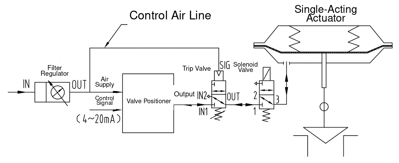
Figure 1. Single-acting modulating control valve with loss-of-air and loss-of-power fail-safe return
Under normal conditions, filtered and regulated instrument air supplies the positioner and the pressure-sensing trip valve. With the solenoid valve energized, the positioner receives the control-room command and regulates pressure to the single-acting actuator.
If the solenoid is de-energized, ports 2 and 3 connect and the actuator signal pressure is vented. If instrument-air pressure falls below the trip setting, the pressure-sensing trip valve switches from its normal path to its failure path and also vents the actuator chamber. The actuator spring then moves the valve to its configured fail-safe position.
Key accessories:
- Filter regulator: filters the instrument air and reduces it to the specified accessory and actuator pressure.
- Positioner: converts the control command into the pneumatic output required to position the valve.
- Pressure-sensing trip valve: detects low supply pressure and initiates the loss-of-air failure action.
- Direct-acting solenoid valve: initiates the loss-of-power failure action. The source specifically requires a direct-acting design so the trip does not depend on a minimum pilot-pressure differential. Coil rating, port configuration, flow capacity, de-energized path, and hazardous-area certification must still be verified.
The source diagram shows 8 mm outside-diameter stainless-steel tubing as a typical control-line size. Final tubing and fitting sizes must be verified against actuator volume, line length, allowable pressure loss, ambient temperature, and required stroking time.
2. Single-Acting On-Off Valve: Loss-of-Air and Loss-of-Power Fail-Safe Return
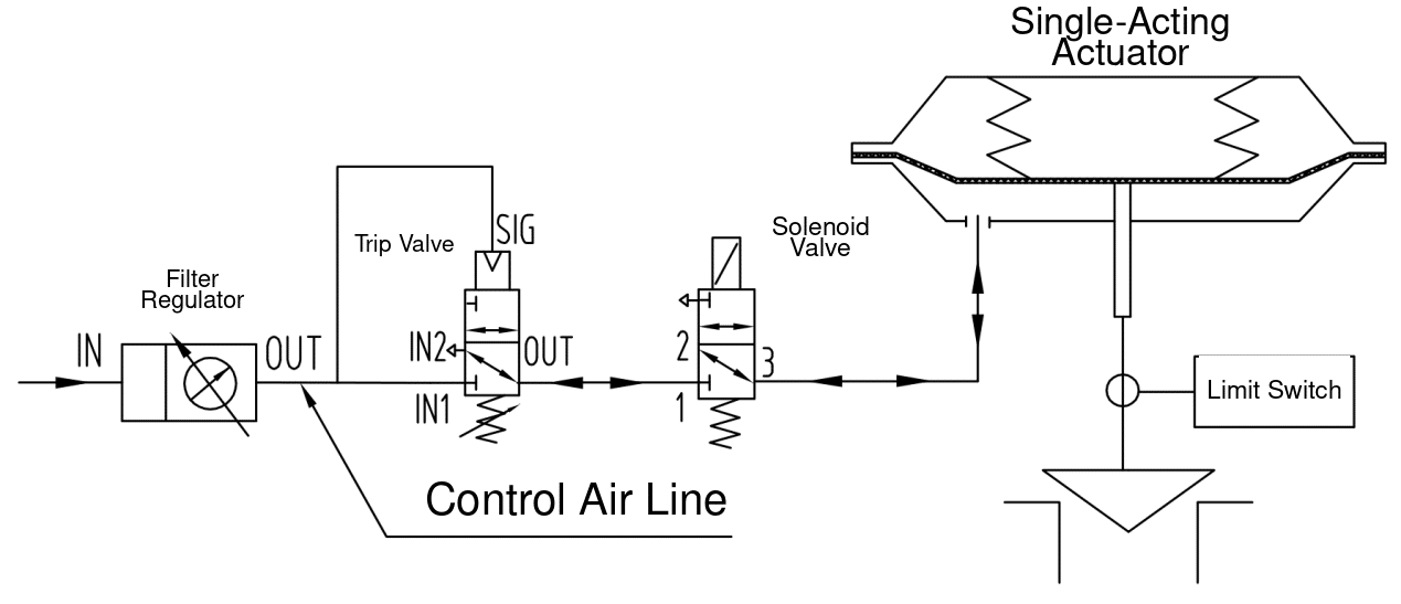
Figure 2. Single-acting on-off control valve with loss-of-air and loss-of-power fail-safe return
During normal operation, the control system energizes or de-energizes the solenoid valve to fill or vent the actuator chamber. A limit switch provides open and closed position feedback.
If the solenoid loses power, ports 2 and 3 connect and the actuator chamber vents. If supply pressure falls below the trip point, the pressure-sensing trip valve changes state and provides an additional vent path. In either event, the spring-return actuator drives the valve to its configured failure position.
Key accessories:
- Filter regulator
- Limit switch or valve position switch
- Pressure-sensing trip valve
- Solenoid valve
The electrical command should be described as a discrete open/close command, not as a generic “voltage signal.” Coil voltage, energized state, de-energized state, hazardous-area approval, power consumption, and manual override requirements must all be stated separately.
3. Single-Acting On-Off Valve, High-Capacity Version: Rapid Fail-Safe Return
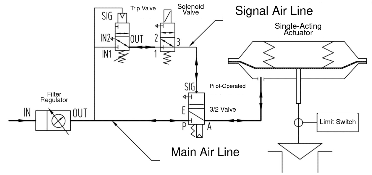
Figure 3. High-capacity single-acting on-off valve circuit with rapid fail-safe return
This circuit adds a pilot-operated 3/2 directional valve so the solenoid and pressure-sensing trip valve only handle pilot flow, while the main directional valve handles the larger actuator flow.
In normal service, the solenoid command controls the pilot pressure to the 3/2 valve, which fills or vents the actuator for on-off operation. On loss of solenoid power or low instrument-air pressure, the pilot signal is vented. The 3/2 valve changes state, connects ports E and A, and rapidly exhausts the actuator chamber. The actuator spring then returns the valve to its failure position.
Key accessories:
- Filter regulator
- Limit switch
- Pressure-sensing trip valve
- Solenoid valve
- Pilot-operated 3/2 directional valve
The pilot circuit may use relatively small tubing, but the main pneumatic path must be sized from the actuator chamber volume and the required opening or closing time. The 10-25 mm stainless-steel tubing range shown in the source is a reference range, not a universal rule.
4. Single-Acting Modulating Valve, High-Capacity Version: Rapid Fail-Safe Return
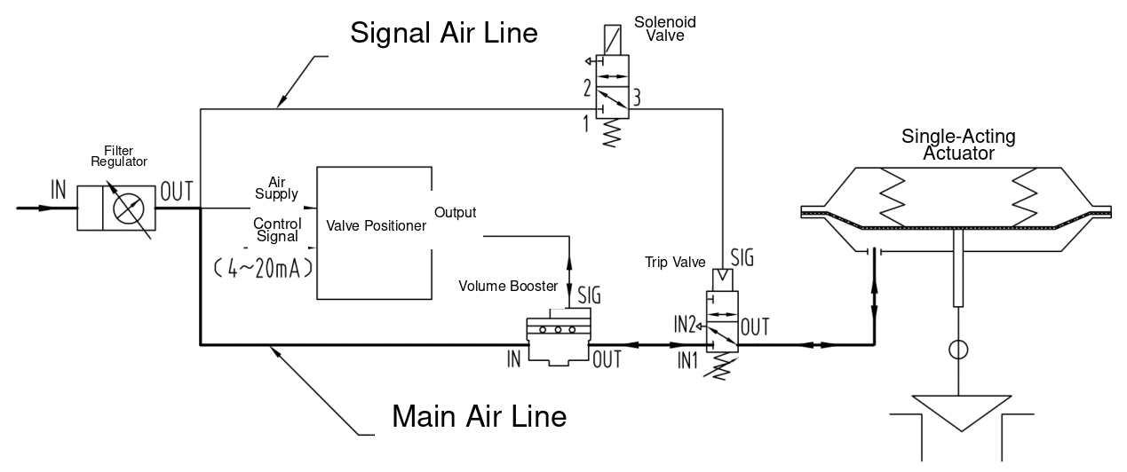
Figure 4. High-capacity single-acting modulating valve with rapid fail-safe return
During normal operation, the positioner controls the actuator through a volume booster. The booster increases supply and exhaust capacity while following the positioner’s output pressure.
If the solenoid is de-energized or the instrument-air pressure falls below the trip setting, the pneumatic control path is switched so the actuator chamber can vent rapidly. The spring-return actuator then drives the valve to its configured fail-safe position.
Key accessories:
- Filter regulator
- Positioner
- Pressure-sensing trip valve
- Solenoid valve
- Volume booster
The booster must be tuned as part of the positioner-actuator loop. Excessive bypass restriction or an incorrectly sized booster can cause overshoot, cycling, or unstable small-signal response. Booster capacity, trip-valve capacity, tubing size, and exhaust capacity must be checked together against the specified full-stroke time.
5. Single-Acting On-Off Valve: Loss-of-Air Fail-in-Place
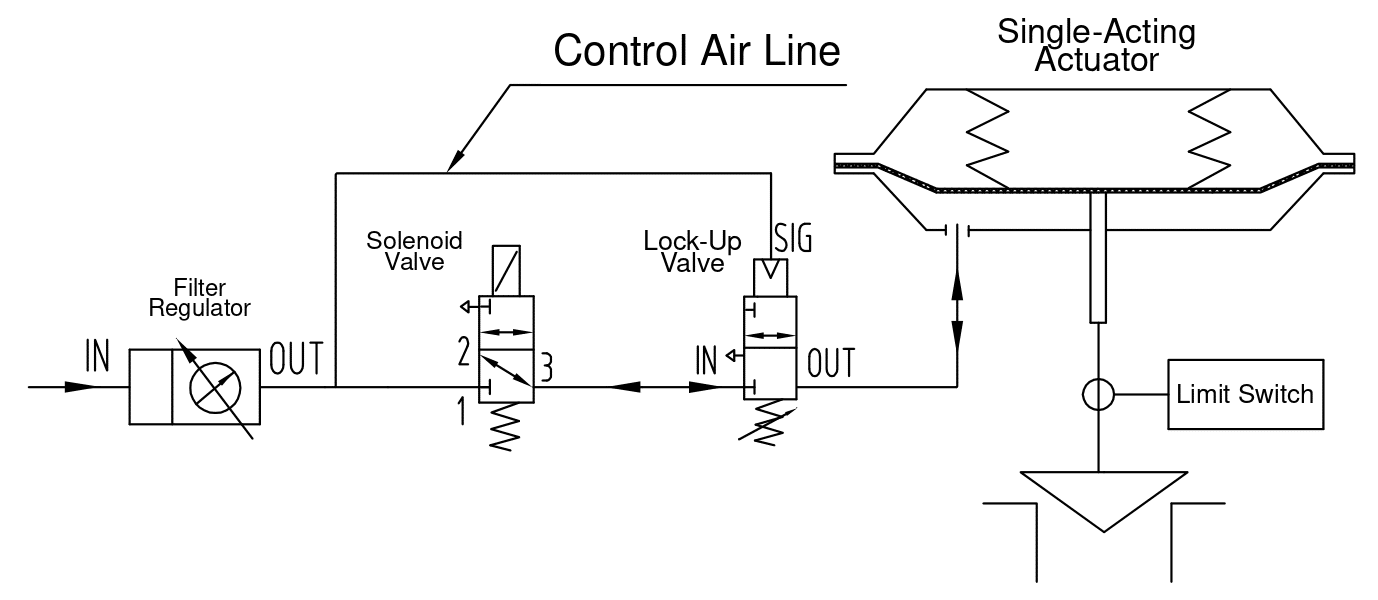
Figure 5. Single-acting on-off valve with pneumatic fail-in-place protection
With normal instrument air, the solenoid valve fills or vents the actuator chamber for open/close operation. If supply pressure falls below the lock-up setting, the pneumatic lock-up valve closes the actuator line and traps the existing chamber pressure. This opposes the actuator spring and holds the valve near its last position.
Key accessories:
- Filter regulator
- Limit switch
- Pneumatic lock-up valve
- Solenoid valve
The circuit does not provide fail-in-place action merely because the actuator is single-acting. The lock-up valve, actuator seals, tubing, and fittings must have sufficiently low leakage to maintain the required position for the specified duration. The project should state an acceptable position drift and hold time rather than using the phrase “remain indefinitely.”
The source correctly notes that ordinary on-off service does not always require fail-in-place on loss of solenoid power. If loss-of-power hold is required, a separate electrical and pneumatic logic arrangement must be defined.
6. Single-Acting Modulating Valve: Loss-of-Air and Loss-of-Power Fail-in-Place
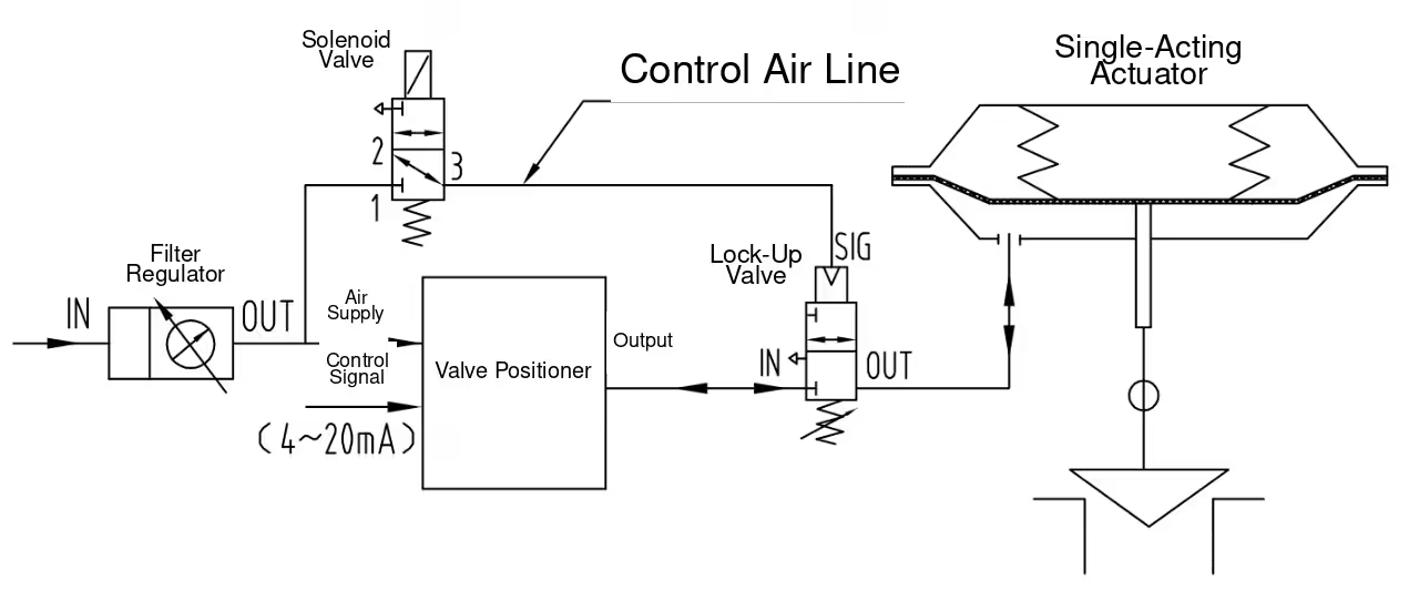
Figure 6. Single-acting modulating valve with loss-of-air and loss-of-power fail-in-place protection
In normal operation, the energized solenoid allows the positioner output to operate the pneumatic lock-up valve and actuator. The positioner modulates the valve according to the control signal.
If the solenoid loses power, its failure path removes the pilot signal from the lock-up valve. If instrument-air pressure falls below the lock-up setting, the same valve closes directly. In either case, the actuator chamber is isolated and the trapped pressure holds the valve near its last position.
Key accessories:
- Filter regulator
- Positioner
- Pneumatic lock-up valve
- Solenoid valve
The solenoid arrangement must be checked carefully so that de-energization isolates the actuator instead of venting it. A conventional fail-vent solenoid installed in the wrong location would cause the single-acting actuator to spring-return rather than fail in place.
7. Single-Acting On-Off Valve, High-Capacity Version: Loss-of-Air Fail-in-Place
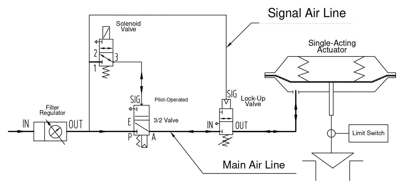
Figure 7. High-capacity single-acting on-off valve with fail-in-place protection
The solenoid valve pilots a higher-flow 3/2 directional valve, which performs the main filling and venting duty for the actuator. During normal operation, this arrangement provides faster on-off travel than routing the full actuator flow through a small solenoid valve.
When instrument-air pressure falls below the adjusted threshold, the pneumatic lock-up valve closes the actuator line and traps the chamber pressure. The valve therefore remains near the position held at the time of the air failure.
Key accessories:
- Filter regulator
- Limit switch
- Pneumatic lock-up valve
- Solenoid valve
- Pilot-operated 3/2 directional valve
The source text omits the subject in the failure sentence. The device that closes is the pneumatic lock-up valve. The lock-up valve and the main 3/2 directional valve must both have adequate flow capacity, and the complete circuit must be leak-tested at the required hold pressure.
8. Single-Acting Modulating Valve, High-Capacity Version: Loss-of-Air and Loss-of-Power Fail-in-Place
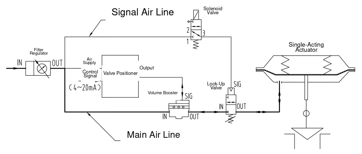
Figure 8. High-capacity single-acting modulating valve with fail-in-place protection
This is the high-capacity version of Circuit 6. In normal service, the positioner and volume booster fill or exhaust the actuator at the rate required for modulating control.
If the solenoid loses power or supply pressure drops below the lock-up setting, the pneumatic lock-up valve closes and isolates the actuator chamber. The trapped pressure holds the valve near its last position.
Key accessories:
- Filter regulator
- Positioner
- Pneumatic lock-up valve
- Solenoid valve
- Volume booster
The original title duplicates Circuit 6 even though the diagram includes a volume booster and a larger main-air path. The “high-capacity version” wording is therefore added to distinguish the two arrangements without changing the circuit logic.
9. Single-Acting Modulating Valve: Three-Failure Fail-in-Place
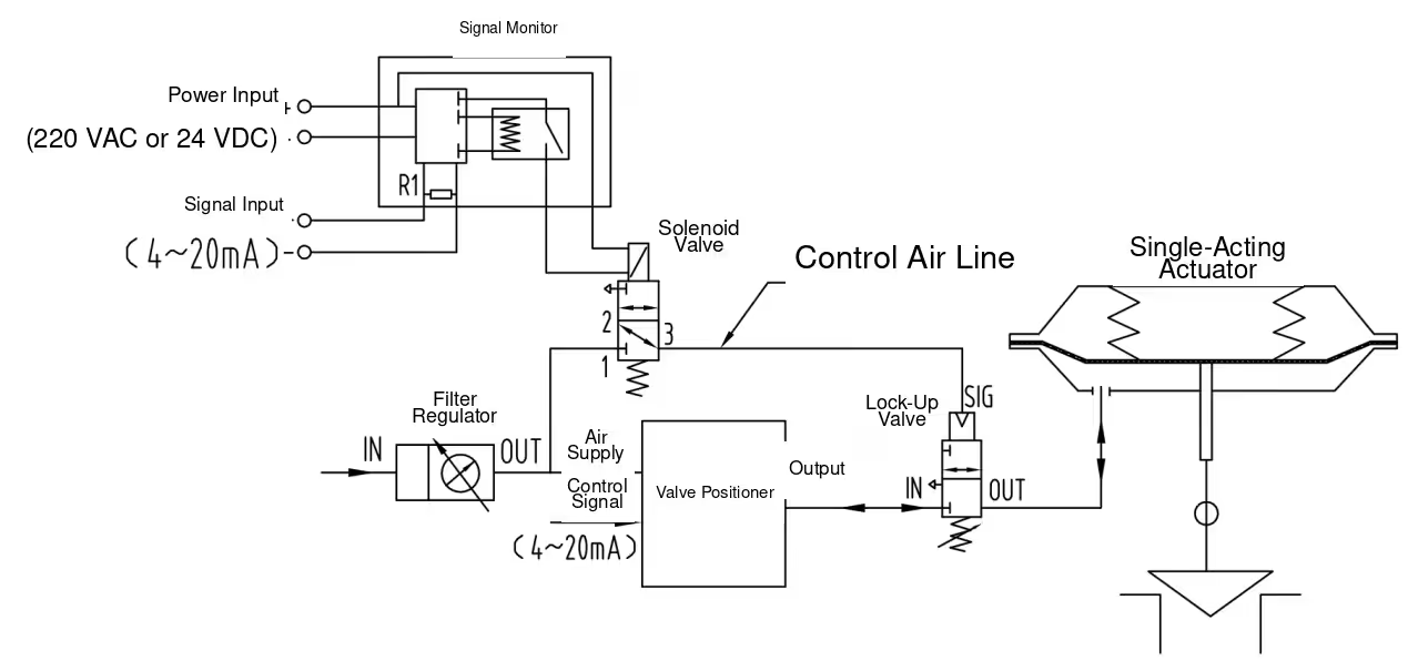
Figure 9. Single-acting modulating valve with loss-of-air, loss-of-power, and loss-of-signal fail-in-place protection
Under normal conditions, the positioner receives the 4-20 mA command and controls the actuator. A current-monitoring relay is connected to the same loop and keeps the solenoid energized while a valid signal is present.
The pneumatic lock-up valve closes under any of three conditions:
- instrument-air pressure falls below its setting;
- solenoid power is lost; or
- the 4-20 mA signal is interrupted and the monitoring relay de-energizes the solenoid.
When the lock-up valve closes, the actuator pressure is trapped and the valve remains near its last position.
Key accessories:
- Filter regulator
- Positioner
- Pneumatic lock-up valve
- Solenoid valve
- 4-20 mA signal-loss monitor or current-monitoring relay
The signal-loss threshold, NAMUR or project-specific failure current, loop loading, electrical isolation, and behavior during positioner diagnostics must be defined. A simple series connection should not be accepted until the loop’s voltage budget and input impedance have been checked.
10. Single-Acting Modulating Valve, High-Capacity Version: Three-Failure Fail-in-Place
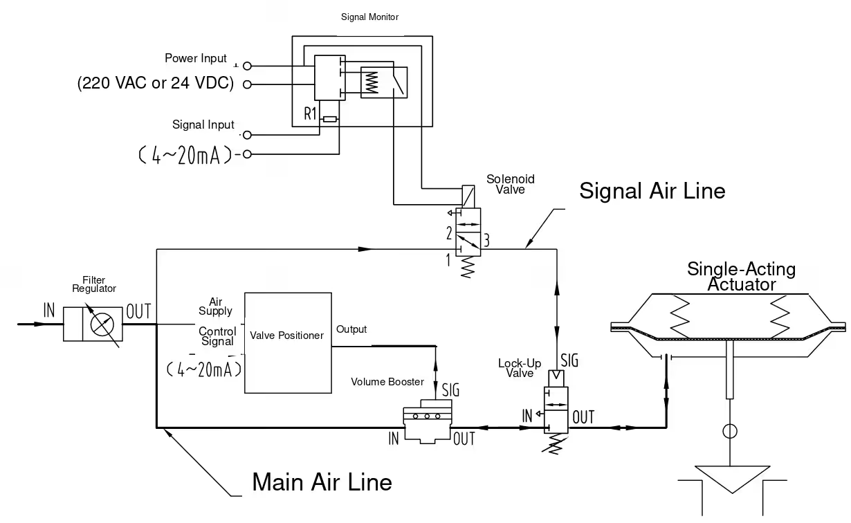
Figure 10. High-capacity single-acting modulating valve with three-failure fail-in-place protection
This circuit combines three-failure detection with a volume booster for higher pneumatic capacity. In normal operation, the positioner controls the actuator through the booster. The solenoid remains energized while power and a valid 4-20 mA signal are available.
Loss of air, loss of solenoid power, or loss of control signal removes the lock-up valve’s pilot condition. The lock-up valve closes, isolates the actuator chamber, and holds the valve near its last position.
Key accessories:
- Filter regulator
- Positioner
- Pneumatic lock-up valve
- Solenoid valve
- Volume booster
- 4-20 mA signal-loss monitor
The volume booster, lock-up valve, supply regulator, and main tubing must be sized as one pneumatic system. The required small-signal stability, emergency response, full-stroke time, and allowable fail-in-place drift should be verified by a complete valve assembly test.
Double-Acting Actuator Circuits
11. Double-Acting On-Off Valve: Stored-Air Fail-Safe Return on Loss of Air or Power
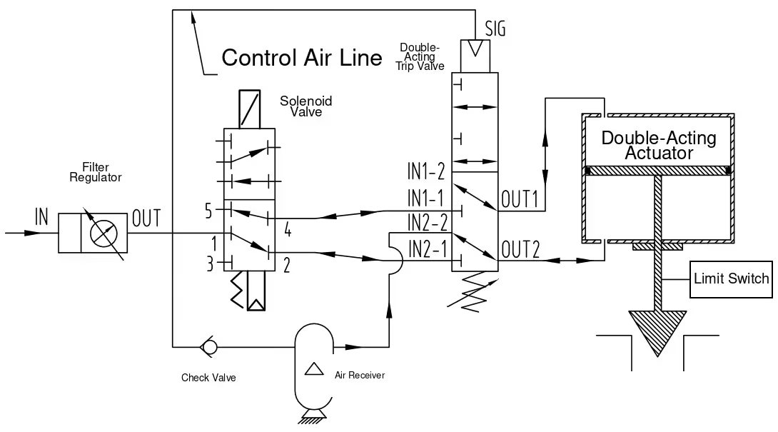
Figure 11. Double-acting on-off valve with stored-air fail-safe return
In normal operation, the solenoid valve directs instrument air to one actuator chamber while venting the other. A check valve charges the air receiver and prevents stored air from flowing back into a failed supply header.
If instrument-air pressure falls below the trip setting, the double-acting pressure-sensing trip valve disconnects normal control. It connects the air receiver to the chamber required for the specified failure direction and vents the opposite chamber. The pressure imbalance moves the valve to its configured fail-safe position.
Loss-of-power action depends on the selected solenoid’s de-energized flow path and its connection to the trip arrangement. The schematic and solenoid port state must be verified together; the title alone is not sufficient.
Key accessories:
- Filter regulator
- Limit switch
- Double-acting pressure-sensing trip valve
- 5/2 solenoid valve
- Air receiver
- Check valve
The source’s “receiver volume equals four times actuator chamber volume” statement is only a preliminary rule of thumb. Final receiver sizing must use the initial receiver pressure, minimum pressure at the end of the failure stroke, actuator chamber volume throughout travel, required number of strokes, dead volume, temperature, leakage, and design margin.
12. Double-Acting On-Off Valve, High-Capacity Version: Rapid Stored-Air Fail-Safe Return
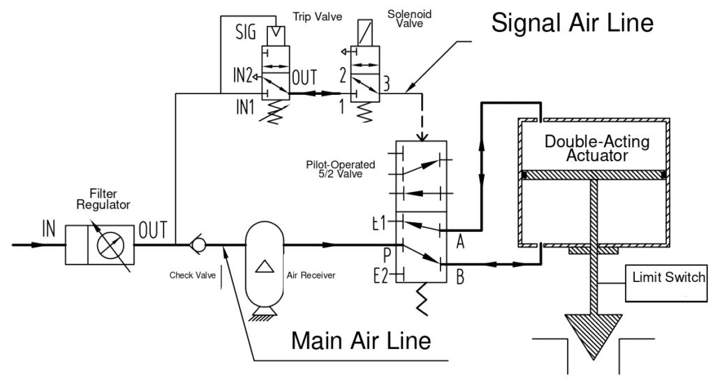
Figure 12. High-capacity double-acting on-off valve with rapid stored-air fail-safe return
The solenoid and pressure-sensing trip valve control the pilot signal to a high-flow 5/2 pilot-operated directional valve. During normal operation, the 5/2 valve alternately supplies and vents the actuator chambers for on-off service.
On loss of solenoid power or low supply pressure, the pilot signal is vented and the 5/2 valve changes to its failure state. The stored air is routed to the required actuator chamber while the opposite chamber is exhausted. This produces a rapid fail-safe stroke.
Key accessories:
- Filter regulator
- Limit switch
- Pressure-sensing trip valve
- Solenoid valve
- Pilot-operated 5/2 directional valve
- Air receiver
- Check valve
Receiver capacity and 5/2 valve flow capacity must both be calculated. A large receiver connected through an undersized valve, silencer, fitting, or tube will not achieve the required fail-safe time.
13. Double-Acting Modulating Valve: Stored-Air Fail-Safe Return on Loss of Air or Power
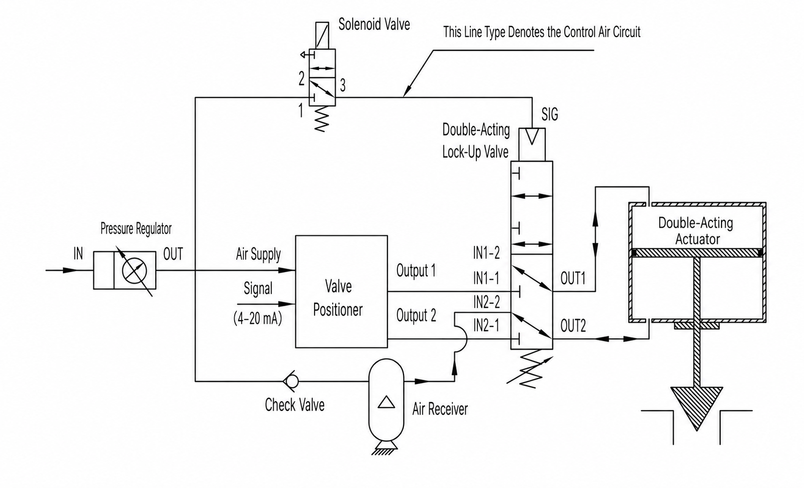
Figure 13. Double-acting modulating valve with stored-air fail-safe return
During normal operation, the double-acting positioner independently controls pressure to the two actuator chambers. A check valve maintains the air receiver at the available supply pressure.
If the solenoid loses power or the supply pressure falls below the trip point, the double-acting pressure-sensing trip valve disconnects the positioner. It supplies stored air to the chamber needed for the specified failure direction and vents the opposite chamber.
Key accessories:
- Filter regulator
- Double-acting positioner
- Double-acting pressure-sensing trip valve
- Solenoid valve
- Air receiver
- Check valve
The source accessory description incorrectly suggests that the solenoid performs ordinary open/close control. In this modulating circuit, the positioner performs continuous control; the solenoid is part of the trip or override logic. Receiver sizing must be calculated rather than fixed at a universal multiple of actuator volume.
14. Double-Acting Modulating Valve, High-Capacity Version: Rapid Stored-Air Fail-Safe Return
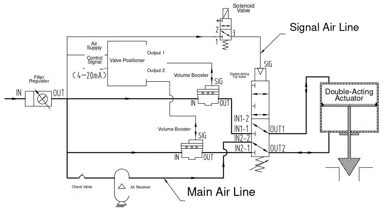
Figure 14. High-capacity double-acting modulating valve with rapid stored-air fail-safe return
Two volume boosters increase the filling and exhaust capacity of the positioner outputs. Under normal conditions, the valve remains under closed-loop positioner control.
If the solenoid is de-energized or supply pressure falls below the trip setting, the double-acting trip valve disconnects normal control and routes stored air to one actuator chamber while venting the other. The valve moves rapidly to the configured fail-safe position.
Key accessories:
- Filter regulator
- Double-acting positioner
- Double-acting pressure-sensing trip valve
- Solenoid valve
- Two volume boosters
- Air receiver
- Check valve
The boosters must be matched and tuned so asymmetric filling and exhaust behavior does not produce overshoot or unstable positioning. Receiver pressure, booster supply routing, check-valve orientation, and the trip valve’s actual port map are critical to achieving the intended failure direction.
15. Double-Acting On-Off Valve: Loss-of-Air Fail-in-Place
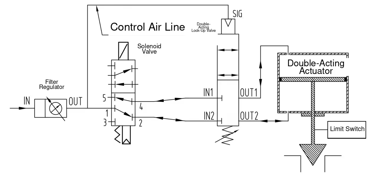
Figure 15. Double-acting on-off valve with loss-of-air fail-in-place protection
During normal operation, the solenoid valve supplies one actuator chamber and vents the other. When supply pressure falls below the set point, the double-acting lock-up valve closes both actuator lines. The pressure in both chambers is trapped, holding the actuator and valve near their last position.
Key accessories:
- Filter regulator
- Limit switch
- Double-acting pneumatic lock-up valve
- 5/2 solenoid valve
The circuit provides loss-of-air hold. It does not automatically provide loss-of-power hold unless the solenoid and lock-up pilot logic are specifically arranged for that purpose. The acceptable drift under changing process force must be defined and tested.
16. Double-Acting Modulating Valve: Loss-of-Air and Loss-of-Power Fail-in-Place
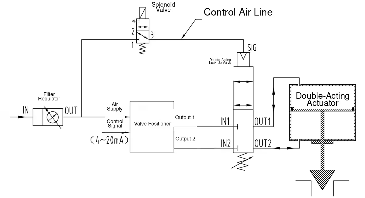
Figure 16. Double-acting modulating valve with loss-of-air and loss-of-power fail-in-place protection
With normal supply pressure and energized solenoid power, the double-acting positioner controls both actuator chambers through the double-acting lock-up valve.
If the solenoid loses power or instrument-air pressure falls below the lock-up setting, the lock-up valve isolates both actuator chambers. The valve then remains near its last position as long as trapped pressures remain sufficient.
Key accessories:
- Filter regulator
- Double-acting positioner
- Double-acting pneumatic lock-up valve
- Solenoid valve
The source accessory list describes the double-acting lock-up valve as providing “loss-of-air reset.” That is inconsistent with the title, diagram, and operating text. Its correct function in this circuit is loss-of-air fail-in-place.
17. Double-Acting On-Off Valve, High-Capacity Version: Loss-of-Air Fail-in-Place
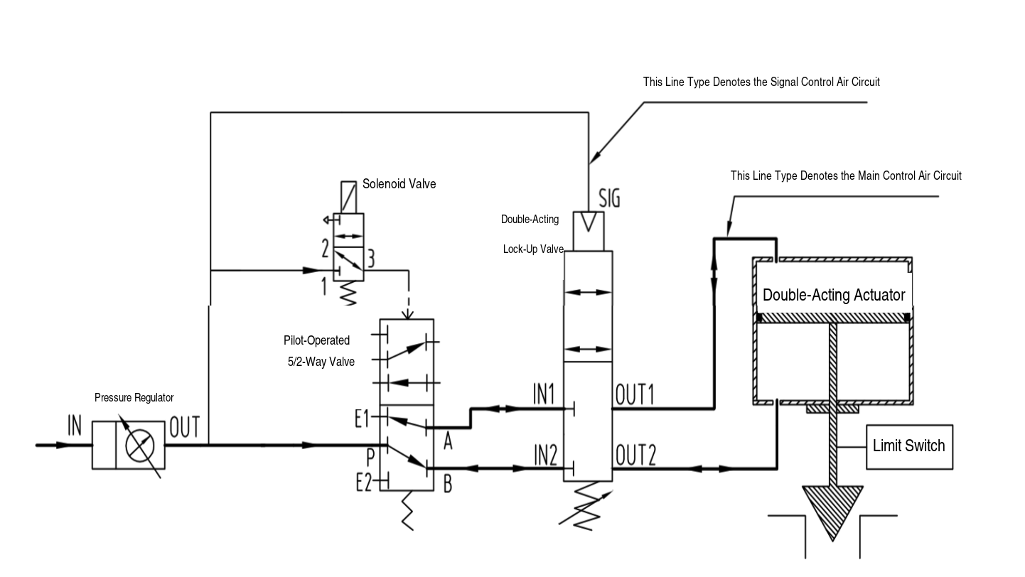
Figure 17. High-capacity double-acting on-off valve with loss-of-air fail-in-place protection
The solenoid pilots a high-flow 5/2 directional valve, which performs the main supply and exhaust switching for the double-acting actuator. When supply pressure is healthy, the circuit provides rapid on-off movement.
If the supply pressure falls below the lock-up setting, the double-acting pneumatic lock-up valve closes both actuator lines and traps chamber pressure. The valve remains near its last position.
Key accessories:
- Filter regulator
- Limit switch
- Double-acting pneumatic lock-up valve
- Solenoid valve
- Pilot-operated 5/2 directional valve
The original accessory list omits the 5/2 pilot-operated valve even though it appears in the diagram and is referenced in the operating text. It must be included in the bill of materials and sized for both supply and exhaust flow.
18. Double-Acting Modulating Valve, High-Capacity Version: Loss-of-Air and Loss-of-Power Fail-in-Place
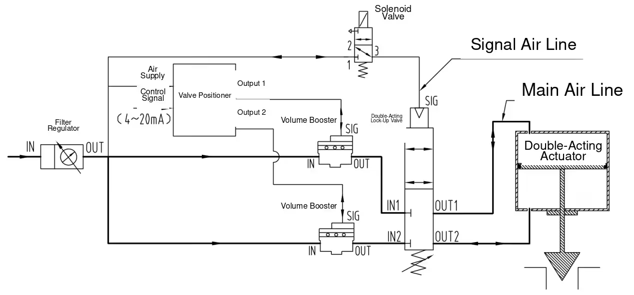
Figure 18. High-capacity double-acting modulating valve with fail-in-place protection
Under normal conditions, the double-acting positioner controls the actuator through two volume boosters. If the solenoid loses power or supply pressure falls below the lock-up setting, the double-acting lock-up valve isolates both actuator chambers. The valve remains near its last position.
Key accessories:
- Filter regulator
- Double-acting positioner
- Double-acting pneumatic lock-up valve
- Solenoid valve
- Two volume boosters
The source operating text says that a pilot-operated 3/2 valve must be sized, but no such valve appears in the diagram. The actual high-flow components shown are the two volume boosters and the double-acting lock-up valve. These components, the tubing, and the exhaust paths must be sized and tested as a system.
19. Double-Acting Modulating Valve: Three-Failure Fail-in-Place
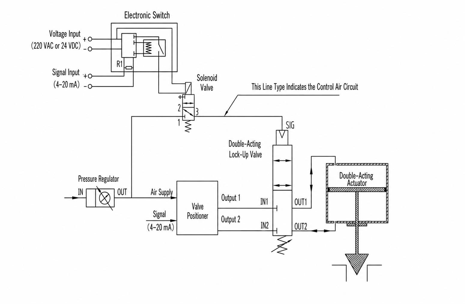
Figure 19. Double-acting modulating valve with loss-of-air, loss-of-power, and loss-of-signal fail-in-place protection
In normal operation, the double-acting positioner controls both actuator chambers. A current-monitoring relay monitors the 4-20 mA loop and keeps the solenoid energized while the signal remains valid.
If air pressure falls below the lock-up setting, if electrical power is lost, or if the control signal is interrupted, the double-acting lock-up valve closes both actuator paths. The valve remains near its last position.
Key accessories:
- Filter regulator
- Double-acting positioner
- Double-acting pneumatic lock-up valve
- Solenoid valve
- 4-20 mA signal-loss monitor
The loop’s allowable burden and signal-failure thresholds must be checked. Projects using live-zero diagnostics should define whether currents below 3.6 mA, above 21 mA, or another range constitute a trip condition.
20. Double-Acting Modulating Valve, High-Capacity Version: Three-Failure Fail-in-Place
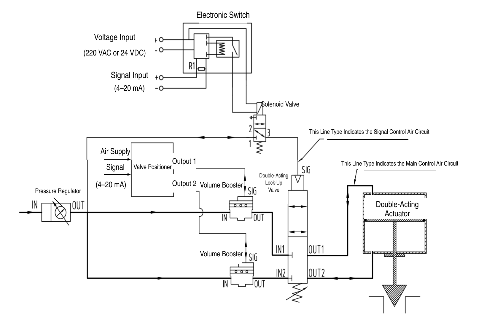
Figure 20. High-capacity double-acting modulating valve with three-failure fail-in-place protection
This arrangement adds two volume boosters to Circuit 19. The positioner controls the actuator during normal operation, while the boosters provide the required high flow. The current-monitoring relay and solenoid create the signal-loss and power-loss trip path.
Loss of air, power, or control signal causes the double-acting lock-up valve to isolate both actuator chambers. The valve holds near its last position.
Key accessories:
- Filter regulator
- Double-acting positioner
- Double-acting pneumatic lock-up valve
- Solenoid valve
- Two volume boosters
- 4-20 mA signal-loss monitor
The system should be tested for both dynamic positioning and failure behavior. A circuit that meets the emergency hold requirement can still be unsuitable if the boosters are not tuned for stable modulating control.
Two-Stage Actuator Circuits
21. Two-Stage Actuator: Three Discrete Valve Positions
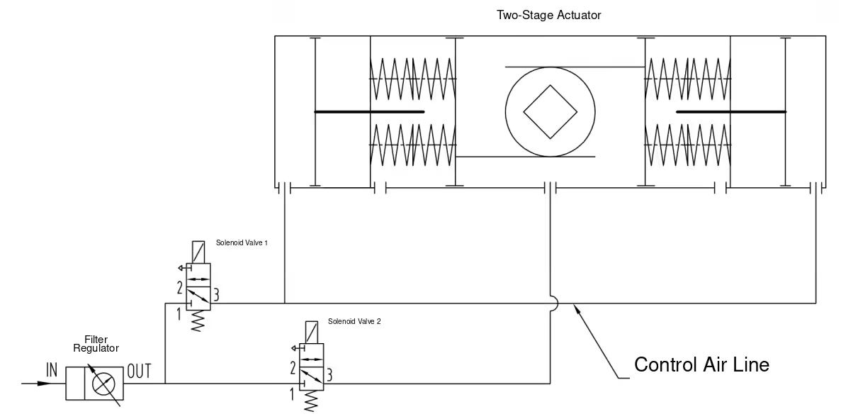
Figure 21. Two-stage actuator controlled by two solenoid valves
This circuit uses two solenoid valves to select three actuator positions. The intermediate position is mechanically or pneumatically adjustable, shown as approximately 45 degrees in the source.
The source logic table is:
| Required Position | Solenoid 1 | Solenoid 2 |
| 0 degrees | De-energized | De-energized |
| Intermediate, approximately 45 degrees | Energized | Energized |
| 90 degrees | De-energized | Energized |
Key accessories:
- Filter regulator
- Solenoid valve 1
- Solenoid valve 2
- Two-stage actuator
This truth table is valid only for the illustrated actuator and port arrangement. The valve manufacturer must issue a project-specific cause-and-effect table that states every possible combination, including transition behavior, loss of air, loss of power to one coil, and simultaneous switching.
22. Double-Acting Two-Stage Actuator: Three Discrete Valve Positions
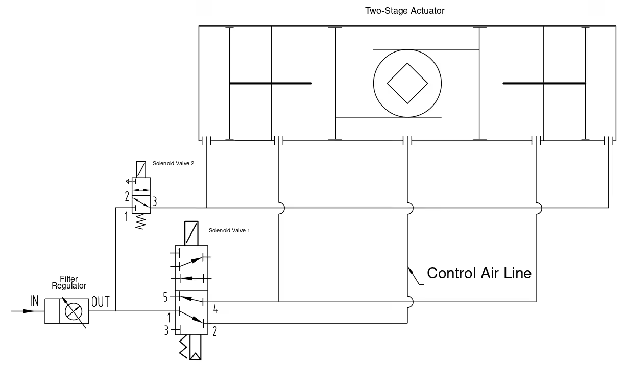
Figure 22. Double-acting two-stage actuator controlled by two solenoid valves
The double-acting two-stage actuator uses separate pneumatic paths to achieve the two end positions and an adjustable intermediate position.
The source logic table is:
| Required Position | Solenoid 1 | Solenoid 2 |
| 0 degrees | De-energized | De-energized |
| 90 degrees | Energized | De-energized |
| Intermediate, approximately 45 degrees | De-energized | Energized |
Key accessories:
- Filter regulator
- 5/2 solenoid valve 1
- 3/2 solenoid valve 2
- Double-acting two-stage actuator
The source does not define the state in which both solenoids are energized. That state must not be left ambiguous in the final design. Electrical interlocking or a fully defined fourth-state response should be provided to prevent conflicting commands.
Special-Purpose Pneumatic Circuits
23. Compressor Anti-Surge Valve: Controlled Modulation with Fast Emergency Opening
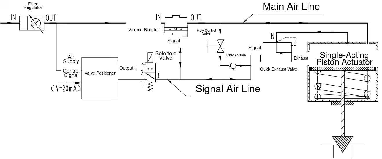
Figure 23. Compressor anti-surge valve pneumatic circuit
An anti-surge valve normally modulates under the positioner’s control but must open very quickly when compressor protection demands it.
With the solenoid energized, the positioner controls the valve through the volume booster. During a closing command, the signal-line pressure increases, the quick exhaust valve remains closed, and the booster supplies the actuator so the valve closes in a controlled manner. During an ordinary opening command, the positioner reduces signal pressure and the actuator exhausts through the controlled flow path for stable opening.
When the solenoid is de-energized, it rapidly vents the pilot line. The quick exhaust valve opens fully and, together with the booster exhaust path, releases actuator pressure at high capacity. The spring-return actuator rapidly opens the anti-surge valve.
Key accessories:
- Filter regulator
- Positioner
- Direct-acting solenoid valve for the required trip duty
- Volume booster
- Adjustable flow restrictor
- Check valve
- Quick exhaust valve
Opening time, overshoot, dead time, small-step response, full-stroke response, and closing stability must be verified by dynamic testing of the complete assembly. Anti-surge performance cannot be established from nominal accessory Cv values alone.
24. Steam Vent Valve: Modulation with Stored-Air Closing on Supply Failure
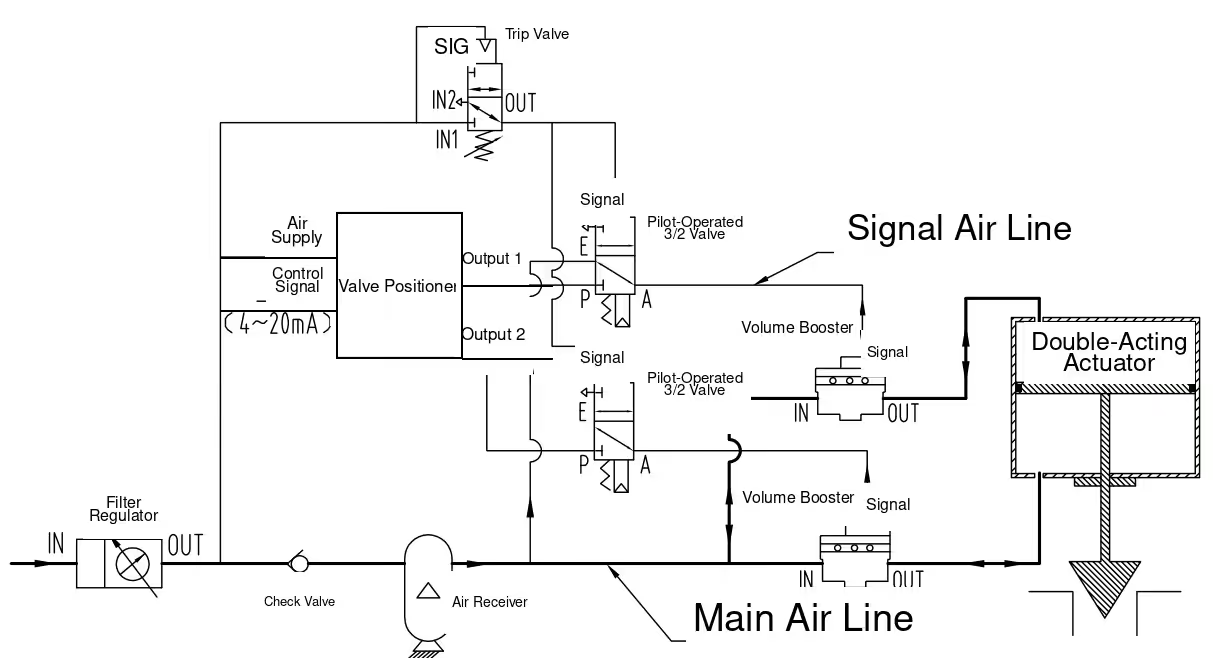
Figure 24. Steam vent valve pneumatic control circuit
With normal instrument air, the pilot-operated 3/2 valve allows the positioner output to control the volume booster. The booster provides the capacity required for modulating the steam vent valve.
If instrument-air pressure falls below the trip setting, the pressure-sensing trip valve vents the pilot signal to the 3/2 valve. The directional valve changes state and connects stored air to the booster signal path. The air receiver then supplies the booster, which pressurizes the actuator chamber needed to close the valve. This prevents unwanted steam-header depressurization after loss of instrument air.
Key accessories:
- Filter regulator
- Positioner
- Volume booster
- Pilot-operated 3/2 directional valve
- Pressure-sensing trip valve
- Check valve
- Air receiver
High acoustic energy and piping vibration can disturb the positioner and accessories. A remote-mounted digital positioner arrangement, remote travel sensor, or separate accessory panel may be considered when measured or calculated vibration and temperature exceed device limits. Remote mounting is not automatically required for every steam vent valve; the feedback method and dynamic response must remain suitable.
25. Turbine Bypass Valve: Multi-Level Priority Control
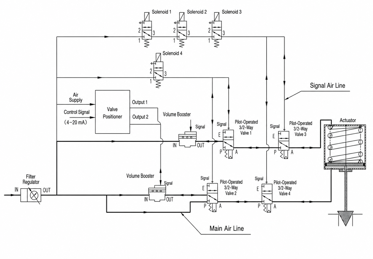
Figure 25. Turbine bypass valve pneumatic priority control circuit
This circuit assigns different command priorities to the positioner and four solenoid valves.
Normal modulating control:
With instrument air available, solenoid 4 de-energized, and solenoids 1, 2, and 3 energized, pilot valves 1 and 2 remain in the E-to-A path while pilot valves 3 and 4 remain in the P-to-A path. The positioner and volume boosters control the actuator for normal modulation.
High-priority rapid closing:
When solenoids 1, 2, and 3 are de-energized, they vent the pilot signals to directional valves 3 and 4. Those valves switch to E-to-A and rapidly exhaust the actuator. The actuator spring closes the bypass valve.
Rapid opening command:
When solenoids 1, 2, 3, and 4 are all energized, all four pilot valves take their P-to-A paths. The upper actuator chamber is exhausted and regulated air is supplied directly to the lower chamber, rapidly opening the valve.
Loss of instrument air:
The actuator spring closes the valve.
Control priority:
- Solenoids 1, 2, and 3: highest priority
- Solenoid 4: second priority
- Positioner command: normal control priority
Key accessories:
- Filter regulator
- Positioner
- Two volume boosters
- Four pilot-operated 3/2 directional valves
- Four solenoid valves
The final project design must include a complete cause-and-effect matrix for all command combinations, transition states, partial power failures, and restoration sequences. The schematic must also define whether reopening after a trip is automatic, permissive-controlled, or manually reset.
26. Self-Actuated Safety Shut-Off Valve: Remote Trip, Local Overpressure Trip, and Manual Reset
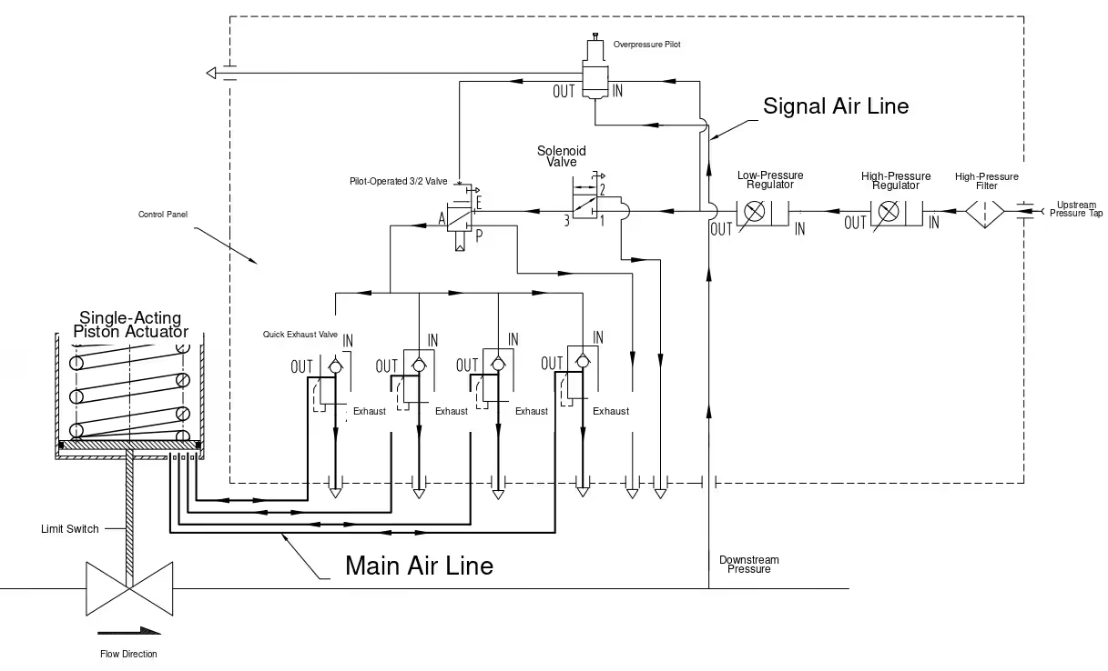
Figure 26. Self-actuated safety shut-off valve with remote and local overpressure trip
The illustrated arrangement uses upstream process gas as the pneumatic energy source. The source example starts at 12 MPa, reduces pressure to 1 MPa through a high-pressure regulator, then reduces it again to 0.5 MPa before the control devices. These values are example-specific and must not be copied into another project without calculation and equipment-rating verification.
Opening and manual reset:
To reopen the safety shut-off valve, the solenoid is energized and manually reset at site. Reduced gas then passes through the solenoid, pilot-operated 3/2 valve, and quick exhaust valve to the actuator, allowing a controlled opening stroke.
Remote emergency closing:
The control room de-energizes the solenoid. The quick-exhaust pilot signal is vented, the quick exhaust valve opens, and the actuator chamber depressurizes rapidly. The shut-off valve closes. Reopening requires a local manual reset.
Local automatic overpressure closing:
An overpressure pilot monitors downstream pressure. At the trip setting, it switches and pilots the 3/2 valve, which vents the quick-exhaust signal. The actuator chamber exhausts rapidly and the safety shut-off valve closes. After downstream pressure has fallen below the reset condition, local manual reset is still required.
Key accessories:
- High-pressure filter
- First-stage high-pressure regulator
- Second-stage low-pressure filter regulator
- Manually reset solenoid valve
- Manually reset pilot-operated 3/2 valve
- Overpressure pilot
- Quick exhaust valves
- Limit switch
Because the pneumatic medium may be combustible process gas, all vents must be routed to a safe location where required. Material compatibility, pressure ratings, regulator failure mode, relief protection, icing, hazardous-area classification, and local code requirements must be reviewed. Quick-exhaust valve quantity and capacity must be selected from actuator volume and required closing time.
27. Delayed Fail Action: Hold, Wait, Then Move at a Controlled Speed
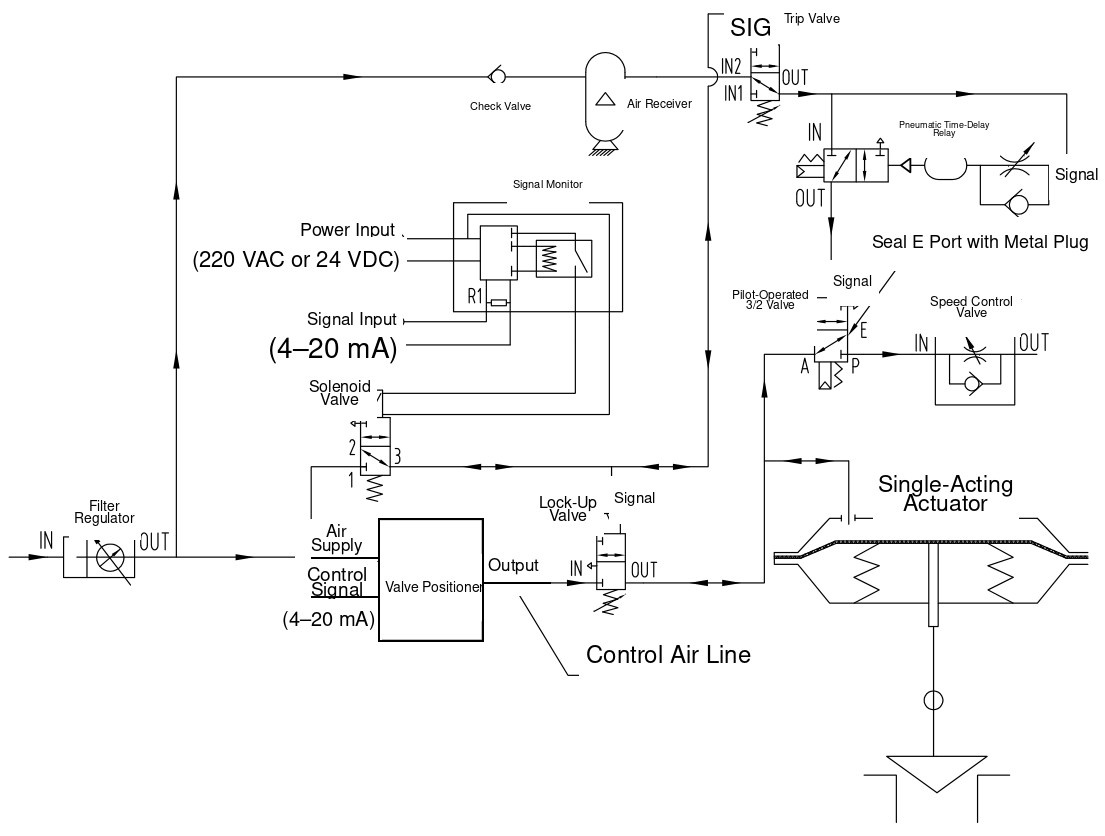
Figure 27. Pneumatic control valve circuit with fail-in-place delay and controlled fail-safe travel
During normal operation, the positioner controls the single-acting actuator. A signal-loss monitor supervises the 4-20 mA loop, while the solenoid and pressure-sensing devices supervise electrical power and instrument-air pressure.
If the control signal is lost, the signal monitor de-energizes the solenoid. The same solenoid failure condition also occurs on direct loss of power. Low instrument-air pressure creates the pneumatic trip condition. Any of these events vents the pilot signals to the lock-up and trip devices.
The sequence is:
- The pneumatic lock-up valve closes immediately and holds the actuator near its current position.
- The pressure-sensing trip valve connects stored air from the receiver to the pneumatic time-delay relay.
- During the adjusted delay period, the time-delay relay remains closed, the 3/2 pilot valve receives no signal, and the actuator remains locked.
- After the delay expires, the time-delay relay supplies the 3/2 pilot valve.
- The 3/2 valve changes state and releases actuator pressure through the adjustable speed-control valve.
- The spring-return actuator moves the valve from the held position toward its configured fail-safe position.
Key accessories:
- Filter regulator
- Positioner
- Solenoid valve
- Pneumatic lock-up valve
- 4-20 mA signal-loss monitor
- Pilot-operated 3/2 directional valve
- Adjustable speed-control valve
- Pneumatic time-delay relay
- Pressure-sensing trip valve
- Check valve
- Air receiver
The source says that the speed control adjusts the time “from fully closed to fully open.” That statement is too specific for the illustrated generic circuit. The actual direction depends on actuator spring orientation and valve action. The correct requirement is the post-delay travel time from the held position to the configured fail-safe position.
Engineering Rules That Apply to All 27 Circuits
1. Define the Failure Position Before Selecting Accessories
The specification must state the required valve position for each independent event:
- loss of instrument air;
- low instrument-air pressure;
- loss of solenoid power;
- loss of 4-20 mA signal;
- loss of positioner electronics;
- loss of both air and power;
- emergency shutdown command;
- restoration of air, power, or signal.
“Fail-safe” without a defined direction and restoration sequence is not a complete requirement.
2. Use a Cause-and-Effect Matrix
For circuits with more than one solenoid, pilot valve, or control system, document every valid and invalid combination. State command priority, transition behavior, reset method, permissives, and whether the valve may move automatically when utilities return.
3. Size the Complete Pneumatic Path
Required stroking time depends on the smallest effective flow area in the entire path. The calculation and test should include:
- filter regulator;
- solenoid valve;
- trip or lock-up valve;
- volume booster;
- pilot-operated directional valve;
- quick exhaust valve;
- tubing length and inside diameter;
- fittings, manifolds, silencers, and flame arresting vents where used;
- actuator chamber volume and pressure throughout travel.
Changing one high-flow accessory will not solve a restriction elsewhere in the circuit.
4. Calculate Air-Receiver Capacity
Do not use a fixed multiple of actuator chamber volume as the final design method. Receiver sizing must consider:
- receiver charging pressure;
- minimum usable pressure at the end of travel;
- actuator volume and pressure requirement;
- required number of full or partial strokes;
- tubing and accessory dead volume;
- leakage and temperature effects;
- design margin;
- applicable pressure-vessel requirements.
5. Verify Fail-in-Place Leakage
A lock-up circuit is a pressure-holding system. Establish:
- maximum allowable valve travel after the trip;
- specified holding duration;
- starting valve position and actuator pressure;
- maximum process force or torque during the hold;
- allowable internal and external leakage;
- test temperature and test medium.
6. Treat Tubing Sizes as Project-Specific
The source diagrams commonly show 8 mm stainless-steel tubing for pilot and signal lines and 10-25 mm tubing for higher-flow paths. These dimensions are useful starting references only. Final selection must be based on the required flow, run length, fittings, supply pressure, actuator volume, ambient conditions, and specified response time.
7. Test the Complete Valve Assembly
The factory acceptance test should verify normal control and every specified fault state. Depending on the circuit, tests should include:
- normal modulation or on-off travel;
- low-air trip setting and reset pressure;
- loss-of-power action;
- loss-of-signal threshold;
- fail-in-place drift;
- emergency full-stroke time;
- opening and closing overshoot;
- delayed-action time and post-delay stroking time;
- limit-switch feedback;
- manual reset and restart sequence;
- leakage from fittings and isolated actuator chambers.
How THINKTANK Converts a Functional Diagram into a Project-Ready Valve Package
A project-ready pneumatic schematic requires more than copying symbols from a typical hook-up. THINKTANK reviews the valve, actuator, accessories, process conditions, failure philosophy, command priority, and timing requirements as one engineered package.
For an accurate proposal, provide:
- valve type, size, pressure class, and required flow direction;
- actuator type and required failure direction;
- available instrument-air pressure range and air quality;
- normal opening and closing times;
- emergency opening or closing time;
- control signal and solenoid power supply;
- loss-of-air, loss-of-power, and loss-of-signal requirements;
- fail-in-place hold time and allowable drift, if applicable;
- hazardous-area classification;
- ambient temperature and environmental protection;
- number of required stored-air strokes;
- reset philosophy and cause-and-effect matrix;
- required testing, certification, and documentation.
THINKTANK can then select the positioner, solenoid valves, trip or lock-up devices, boosters, directional valves, receiver, tubing, and fittings; issue a project-specific pneumatic schematic; and verify the completed assembly through functional and stroking tests.
Conclusion
The same pneumatic actuator can produce very different failure behavior depending on the accessory circuit connected to it. A reliable design therefore begins with the required action for each fault, then works backward through the actuator, pneumatic logic, stored-energy requirement, flow capacity, electrical logic, and reset sequence.
The 27 circuits in this guide provide a structured starting point. They should be adapted to the selected accessory models and verified against the final valve assembly rather than copied as universal installation drawings.
Free Download This Complete Guide
Technical Validation Sources
- Emerson, Fisher 377 Pressure-Sensing Trip Valve: https://www.emerson.com/en/final-control/products/fisher-377
- Emerson, Fisher 377 Trip Valve Instruction Manual: https://www.emerson.com/is/content/emerson/en/final-control/flow-controls/documents/d200319x012.pdf
- SAMSON, Type 3709 Pneumatic Lock-Up Valve: https://www.samsongroup.com/document/t83910en.pdf
- Emerson, Fisher 2625 Series Volume Boosters: https://www.emerson.com/en/final-control/products/fisher-2625
- Emerson, Optimized Anti-Surge Control Valves: https://www.emerson.com/is/content/emerson/en/final-control/flow-controls/solutions/common-applications/surge-valves/compressor-anti-surge-control-valves/documents/brochure-fisher-optimized-antisurge-control-valves-en.pdf
- SMC, Pneumatic Air Consumption and Required Flow Capacity Selection: https://www.smcworld.com/select/accs/en-jp/index.html
- SMC, Air Tank Selection: https://www.smcworld.com/select/atmss/en-jp/index.html