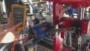
When a control valve will not fully close, do not start by adjusting the positioner.
Start with one simple field check:
Does the valve stem actually reach its fully closed mechanical position?
That observation immediately separates the problem into two very different troubleshooting paths.
- If the stem does not reach the closed position: check the control signal, positioner, instrument air, actuator, stem adjustment and mechanical friction.
- If the stem reaches the closed position but flow still passes through the valve: focus on the plug and seat, trapped debris, shutoff differential pressure, actuator seating force and specified leakage class.
This distinction can save considerable troubleshooting time.
First Check: What Is the Valve Actually Doing?
Use the following symptoms to narrow down the problem before removing the valve from the pipeline.
| What You Observe | Most Likely Area to Check |
|---|---|
| Stem does not reach the closed position | Positioner, air supply, actuator, stem adjustment |
| Stem reaches closed position but valve still leaks | Plug, seat, debris, leakage class |
| Valve closes offline but leaks when process pressure rises | Actuator thrust, shutoff differential pressure |
| Valve movement is slow or unstable | Air supply, packing friction, positioner |
| Leakage becomes worse over time | Seat erosion, cavitation, flashing |
| Newly installed valve has never shut off properly | Adjustment, flow direction, actuator sizing, valve selection |
| Seat is repeatedly repaired but fails again | Process conditions or trim design |
A useful troubleshooting sequence is:
DCS Signal → Positioner → Instrument Air → Actuator → Stem Travel → Valve Trim → Process Conditions
Do not dismantle the valve until the external control and actuation system has been checked.
Step by Step Troubleshooting Guide
1. The Positioner Is Not Driving the Valve Fully Closed
Symptom
The DCS commands 0% valve position, but the valve stem stops before reaching its mechanical closed position.
Check
Verify:
- actual 4–20 mA input signal
- positioner indicated position
- positioner output pressure
- travel calibration
- zero and span settings
- actuator configuration
- feedback linkage or position sensor
- mechanical travel stops
Smart positioners such as Fisher DVC, Siemens SIPART PS2, ABB, SAMSON and Masoneilan SVI can usually provide useful travel and diagnostic information.
A 0% indication on the DCS, however, does not automatically mean that the plug is physically seated.
Action
Stroke the valve and confirm actual stem travel against the valve’s rated travel.
If the positioner reaches its commanded position before the plug reaches the seat, recalibrate the travel and inspect the mechanical stem connection.
2. Instrument Air Pressure Is Too Low
Symptom
The valve moves normally under light process conditions but cannot achieve full travel or tight shutoff when the process pressure increases.
Valve response may also become slow or inconsistent.
Check
Measure the actual air pressure at the positioner or actuator while the valve is operating.
Inspect:
- instrument air supply
- air filter regulator
- blocked filter element
- pneumatic tubing size
- fittings
- air leakage
- actuator diaphragm
- piston seals
- positioner pneumatic output
Do not rely only on the main plant air-header pressure. Pressure available at the actuator can be considerably lower if there is a restriction or leakage in the local pneumatic circuit.
Action
Restore the required supply pressure and eliminate restrictions or leaks.
If the actuator still cannot close the valve at the correct air pressure, actuator thrust should be checked against the process conditions.
3. The Actuator Does Not Have Enough Shutoff Force
This is one of the most important checks when a valve closes normally at low pressure but leaks during actual operation.
Symptom
The valve:
- closes successfully during shutdown;
- passes a bench or workshop stroke test;
- works at low differential pressure;
but begins leaking when upstream pressure increases.
Check
Compare the actuator’s available seating force with the maximum differential pressure across the closed valve.
A common selection mistake is to size the actuator only around the normal throttling pressure drop.
For shutoff, the critical condition may be completely different.
The actuator must overcome:
- hydraulic force on the plug
- packing friction
- stem and guide friction
- spring force
- required seat load
The practical relationship is:
Available actuator thrust must exceed process force, friction and required seating force with adequate margin.
Action
If the actuator is undersized, possible solutions include:
- increasing actuator size
- increasing available air pressure within actuator limits
- reviewing spring selection
- using a different actuator configuration
- considering balanced trim for high differential pressure applications
Repeated positioner calibration will not correct an actuator that simply does not have enough thrust.
4. The Stem or Actuator Travel Is Incorrectly Adjusted
Symptom
The actuator reaches the end of its stroke, but the plug still does not apply sufficient load to the seat.
This is often seen after:
- actuator replacement
- diaphragm replacement
- valve overhaul
- stem disassembly
- field adjustment
Check
Verify:
- valve rated travel
- actuator rated travel
- stem connector position
- bench set
- spring preload
- travel stop
- plug-to-seat contact
Action
Readjust the stem connection according to the valve and actuator design.
The objective is not simply to make the travel indicator show 0%. The plug must reach the correct mechanical position and develop the required seating force.
5. Packing Friction or Stem Binding Prevents Full Travel
Symptom
The valve movement is jerky, slow or inconsistent.
Other signs may include:
- hysteresis
- high deadband
- valve sticking near closed position
- large difference between command and actual travel
Check
Inspect:
- packing compression
- stem condition
- guide alignment
- actuator alignment
- corrosion
- thermal expansion
- contaminated packing
One useful field clue is that the positioner output pressure continues increasing while stem movement stops or becomes difficult.
Action
Correct the mechanical friction rather than compensating for it through excessive positioner tuning.
If packing is repeatedly overtightened to solve external leakage, review the packing material and packing arrangement.
6. Debris Is Trapped Between the Plug and Seat
Symptom
The valve previously shut off correctly but suddenly begins passing flow.
The problem may appear after:
- commissioning
- pipeline fabrication
- maintenance work
- upstream equipment repair
Check
Possible contaminants include:
- welding slag
- rust
- scale
- gasket fragments
- sand
- catalyst particles
- process solids
Cycling the valve may sometimes dislodge loose debris, but forcing the valve repeatedly against hard contaminants can also damage the sealing surfaces.
Action
If cycling does not restore shutoff, isolate and inspect the valve.
More importantly, find the source of the contamination.
If solids are an ongoing process condition rather than a commissioning problem, the valve or upstream piping arrangement may need to be redesigned.
7. The Plug or Seat Is Already Damaged
Symptom
The valve reaches the fully closed position, but internal leakage remains.
Leakage may gradually increase over weeks or months.
Check
Inspect the sealing surfaces for:
- erosion
- scratches
- pitting
- wire drawing
- deformation
- hardfacing damage
- soft-seat damage
Look carefully at the damage pattern.
The way a seat fails can often tell you more than the fact that it failed.
For example, localized pitting may indicate cavitation, while directional erosion may point toward excessive velocity or particles.
Action
Minor damage may be repairable by lapping or replacing the trim.
But if the same seat repeatedly fails after repair, do not keep treating it as a maintenance problem.
Review the actual operating conditions and valve selection.
8. Shutoff Differential Pressure Is Higher Than Expected
Process conditions rarely remain exactly as they were on the original valve datasheet.
Symptom
The valve once worked correctly but starts developing leakage after process changes.
Common changes include:
- higher upstream pressure
- lower downstream pressure
- increased plant capacity
- different pump operating point
- compressor changes
- startup or shutdown conditions
Check
Compare the original valve sizing data with the actual current process conditions:
- maximum upstream pressure
- minimum downstream pressure
- maximum shutoff differential pressure
- actuator thrust
- trim type
A valve designed around a normal operating ΔP of 5 bar may behave very differently if it is later required to close against 20 bar.
Action
Recalculate the shutoff requirement.
If actual differential pressure exceeds the original design basis, the solution may require a larger actuator or a different trim design.
9. The Required Leakage Class Is Being Misunderstood
A control valve reaching the closed position does not necessarily mean zero flow should pass through it.
Symptom
The valve appears mechanically healthy, but maintenance personnel consider any detectable leakage unacceptable.
Check
Confirm the specified seat leakage class.
Control valves may be designed to leakage requirements such as:
- Class II
- Class III
- Class IV
- Class V
- Class VI
A standard metal-seated throttling valve should not automatically be expected to provide the same shutoff performance as a dedicated isolation valve.
Action
Compare the measured leakage with the specified acceptance criterion before deciding the valve has failed.
If the process genuinely requires tighter shutoff than the existing valve can provide, the seat design or valve type may need to change.
10. Cavitation, Flashing or High Velocity Is Destroying the Trim
This is where a repeated maintenance problem often becomes an engineering problem.
Symptom
The valve develops:
- repeated seat damage
- unusual noise
- vibration
- rapid erosion
- increasing leakage shortly after repair
Check
Review the process rather than only the damaged seat.
Look at:
- inlet pressure
- outlet pressure
- liquid vapor pressure
- pressure recovery
- valve opening
- fluid velocity
- actual Cv requirement
An oversized valve can also contribute to the problem.
If the valve operates most of the time at very low opening, high localized velocity close to the seat may accelerate trim wear.
Action
Depending on the service, the solution may involve:
- multi-stage pressure reduction
- labyrinth trim
- anti-cavitation trim
- hardened trim materials
- reduced-capacity trim
- larger valve body with smaller trim
- angle-body construction
- revised valve sizing
If a seat is repaired three times and fails the same way three times, replacing the seat a fourth time is unlikely to address the root cause.
When Recalibrating the Positioner Will Not Solve the Problem
Positioner calibration is often the first action taken when a control valve does not shut off properly.
But stop recalibrating the positioner if all of the following are true:
- the correct control signal reaches the positioner;
- the stem reaches its mechanical closed position;
- positioner travel feedback is normal;
- instrument air pressure is adequate;
- process leakage still remains.
At this point, the likely problem is downstream of the positioner.
Check:
Plug / Seat → Shutoff ΔP → Actuator Seating Force → Leakage Class → Trim Damage
This is usually a much faster diagnostic path than repeatedly adjusting the instrumentation.
Maintenance Problem or Valve Selection Problem?
This distinction matters.
A control valve may simply require maintenance if the problem is:
- contaminated trim
- incorrect calibration
- air leakage
- loose linkage
- packing adjustment
- normal seat wear
But repeated failures should trigger an engineering review.
Watch for:
- repeated seat replacement
- recurring cavitation damage
- actuator operating close to maximum output
- continuous high noise or vibration
- unstable control
- recurring stem or guide damage
- leakage returning shortly after overhaul
These symptoms can indicate that the original valve is no longer suitable for the service.
Review:
- minimum, normal and maximum flow
- calculated Cv
- valve opening at each operating condition
- maximum shutoff differential pressure
- actuator thrust
- cavitation or flashing risk
- trim design
- material selection
- required leakage class
A control valve should be evaluated as a complete system:
Process Conditions → Valve Body → Trim → Actuator → Positioner → Pneumatic Accessories
Before Replacing the Valve, Collect These Operating Conditions
When an existing control valve repeatedly fails, the original nameplate alone is usually not enough to select a better replacement.
Collect:
| Process Data | Valve Data |
| Fluid | Valve size |
| Minimum / normal / maximum flow | Pressure class |
| Inlet pressure | Body material |
| Outlet pressure | Trim material |
| Maximum shutoff ΔP | Rated Cv |
| Operating temperature | Leakage class |
| Density / specific gravity | Fail action |
| Vapor pressure for liquids | Actuator type |
| Molecular weight for gases | Available air pressure |
| Process abnormalities | Positioner model |
The original datasheet is extremely useful, but the current operating conditions are even more important if the process has changed since the valve was installed.
Replacing an Existing Fisher, Masoneilan, SAMSON, KOSO or Other Control Valve
When an existing control valve repeatedly suffers from leakage, cavitation, erosion or insufficient shutoff force, copying the original size and Cv may simply reproduce the same problem.
Before proposing a replacement, THINKTANK engineers can review:
- original valve datasheet and nameplate
- actual operating conditions
- Cv and valve opening
- maximum shutoff differential pressure
- actuator thrust
- required leakage class
- cavitation and flashing conditions
- trim design
- body and trim materials
- actuator and positioner configuration
With more than 30 years of control valve industry experience, THINKTANK supports engineered replacement of Fisher, Masoneilan, SAMSON, KOSO and other control valves when customers are looking for a technically compatible and more cost-effective solution.
The goal is not simply to manufacture another valve with the same dimensions.
The goal is to determine why the existing valve is failing and prevent the same problem from happening again.