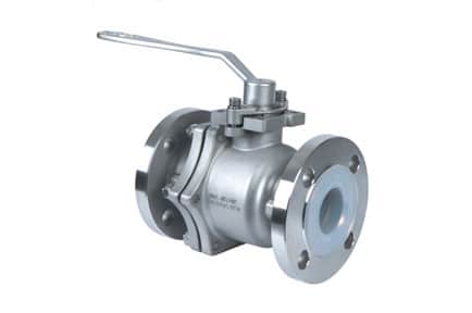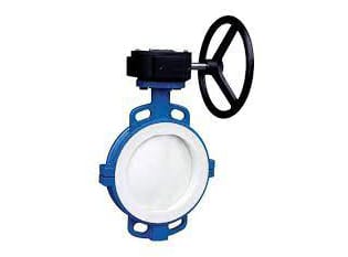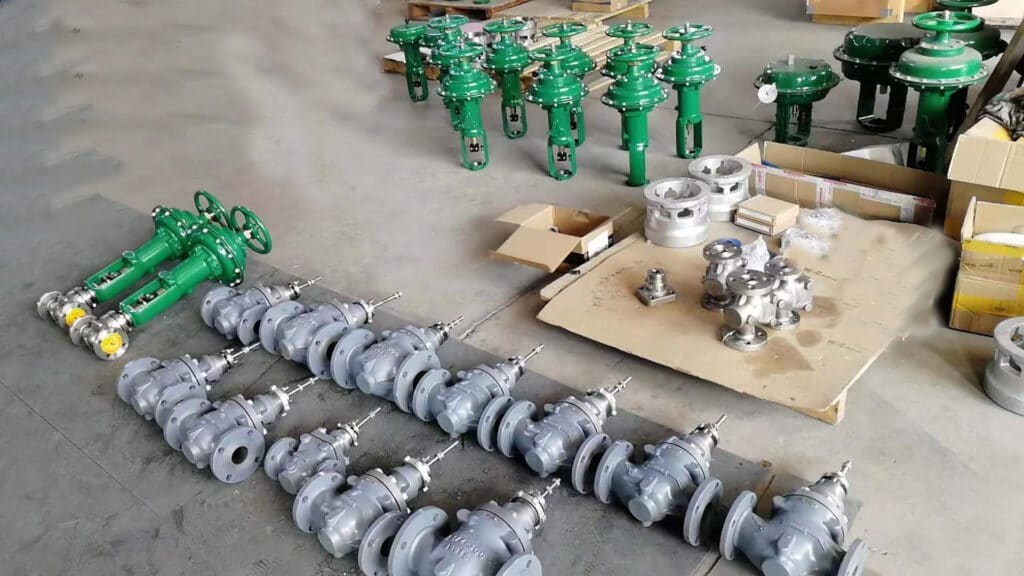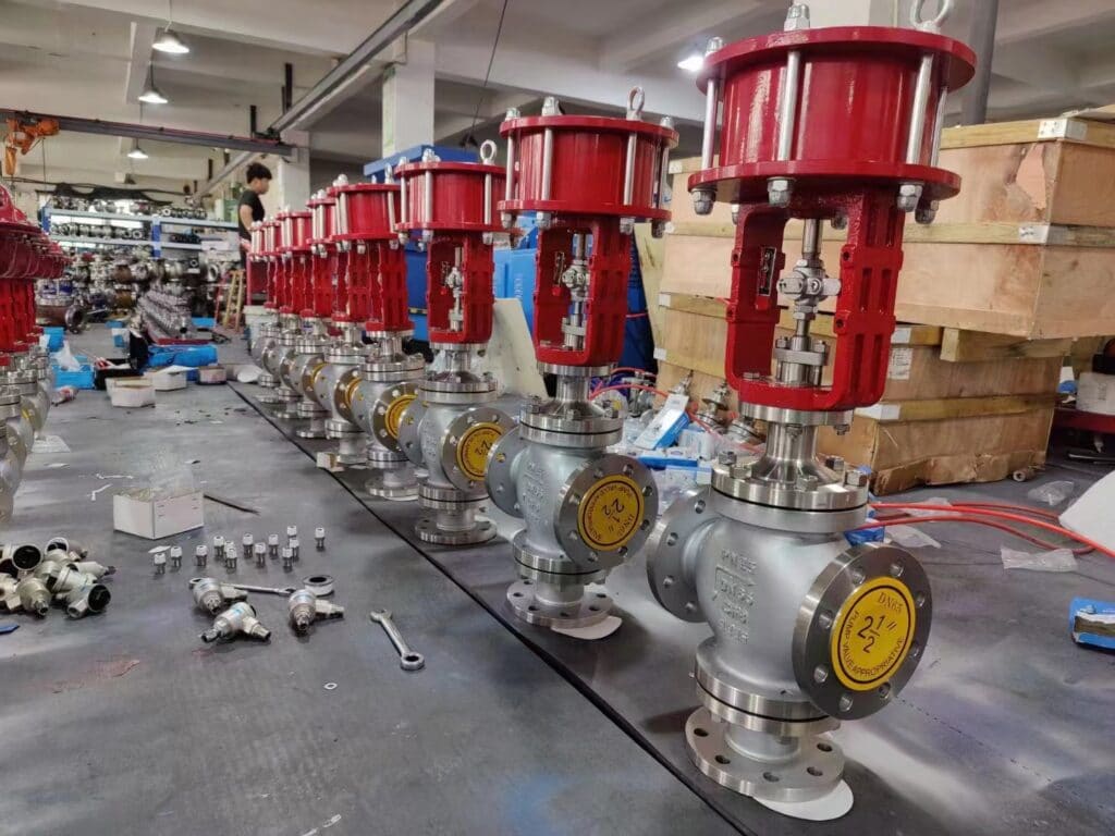
Chemical valve selection requires special consideration of the scientific nature of the valve material. Usually, there is a misunderstanding that stainless steel is a “universal material”, regardless of what media and environmental conditions are using stainless steel valves, which is incorrect. In the following sections, we will analyze the selection of materials for common chemical media and other factors to match a valve to the chemical processing.
Valve Material Selection
Valve for Sulfuric Acid
As one of the strong corrosive media, sulfuric acid is a very wide range of important industrial raw materials. Different concentrations and temperatures of sulfuric acid have varying effects on the corrosion of materials. For concentrations above 80%, the temperature is less than 80 ℃ of concentrated sulfuric acid, it is a high-speed flow of sulfuric acid, carbon steel and cast iron are not suitable as valve materials, ordinary stainless steel such as 304 (0Cr18Ni9), 316 (0Cr18Ni12Mo2Ti) on the sulfuric acid medium corrosion resistance is also very limited. Therefore, industrial valves for conveying sulfuric acid are usually made of high silicon cast iron (but casting and processing are very difficult), and high alloy stainless steel (#20 alloy). The most reliable is to choose valves lined with fluorine material, because fluorine plastic has better resistance to sulfuric acid, and compared with high alloy stainless steel, fluorine lined valves are a more economical choice.
Valve for Hydrochloric Acid
Most metallic materials are not resistant to hydrochloric acid corrosion (including various stainless steel materials), and molybdenum-containing high-silicon iron can only be used for 50 ℃, 30% below hydrochloric acid. Contrary to metal materials, most non-metallic materials have good corrosion resistance to hydrochloric acid, so rubber-lined valves and plastic valves (such as polypropylene, fluorine plastic, etc.) are a better choice for conveying hydrochloric acid.
Valve for Nitric Acid
General metal materials in nitric acid will be rapidly corroded and destroyed, stainless steel in nitric acid-resistant materials has a wide range of applications. In different concentrations of nitric acid at room temperature, stainless steel has good corrosion resistance. Please note that the corrosion resistance of molybdenum-containing stainless steels (such as 316, 316L) to nitric acid is not only worse than that of ordinary stainless steels (such as 304, 321), but the performance is even inferior to that of stainless steels without molybdenum such as 304. And for high-temperature nitric acid, titanium and titanium alloy materials are usually required.
Valve for Acetic acid
Acetic acid is one of the organic acid corrosive substances, ordinary steel in different concentrations and temperatures of acetic acid will be serious corrosion, stainless steel is excellent acetic acid-resistant material, molybdenum-containing 316 stainless steel can also be applied to high temperature and dilute acetic acid vapor. For high temperature and highly concentrated acetic acid or containing other corrosive media and other demanding requirements, high alloy stainless steel valves or fluorine plastic valves can be used.
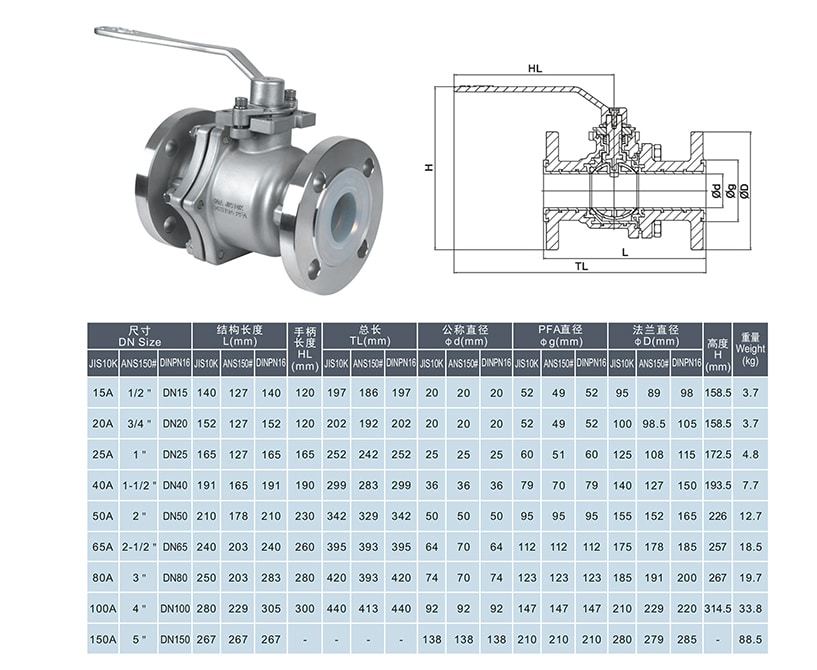
Chemical processes require valves to handle a variety of functions related to various liquids and gases, such as opening or closing flow, controlling flow rates, preventing backflow or backflow, and regulating pressure or relieving pressure.
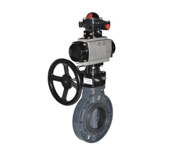
Valves can also be classified as linear or rotary depending on the movement of the closing components, such as globe valves (linear) and butterfly valves (rotary).
Valves can be classified according to the shape of their closing parts, such as gate valves, globe valves, plug valves, diaphragm valves, or butterfly valves.
Depending on the application and pressure and temperature conditions, such as the need for fire-resistant valves. Some valves only require manual actuation. Power actuators are used if the valve is located far from the mechanism, needs a frequent operation, or must automatically respond to the dynamic parameters of the control system, such as adjustment of flow, temperature, or pressure.
Valve Parts
Valve Body
The valve body houses all the internal working parts of the valve and includes the flange. Inside the valve body, the shutoff element moves to adjust the flow of fluid through the valve. To shut off the fluid, the mating surface of the shutoff element is pressed against the valve seat to achieve a tight shutoff. The seat is usually attached to the valve body, and most valves have a metal closure element that seals against a flexible, resilient seat. Sometimes the seat may also be metal, which is selected depending on the service conditions. The distance that the closure element travels from fully open to fully closed is called the valve stroke.
Valve Stem
The stem is the part that connects the valve’s actuator to the closing element. The stem can pass through the bonnet (protected from leakage by the stem packing box) and then connect the closing element for movement. However, many valves (such as rotary plugs and some ball designs) do not have a bonnet.
Bonnet
Bonnets are usually screwed or bolted semi-permanently to the valve body. Different valves have different bonnet designs. The bonnet usually needs to be removed if routine maintenance or servicing is required.
Packing Box
The packing box is the internal area between the valve stem and the bonnet that contains the packing that seals the stem to prevent leakage to the outside of the valve. The packing nut on the bonnet is usually used to compress the packing.
In many valve designs, the bonnet has a back seat to seal the stem to avoid leakage into the packing when the valve is in the fully open position. A bushing on the stem provides the mating surface. The back seat also prevents the stem from ejecting from the valve if the packing begins to leak.
Different fluid characteristics can also affect valve operation. For example, the lubricity of the fluid will determine the actual operating torque of the valve. Gases usually do not require lubrication to be considered. In particular, fluids carrying solids can clog the moving gap between the stem and other components, thus greatly increasing the torque required, sometimes by twice or more than a clean fluid. Over time, rusted internal parts can also increase resistance, so we need to maintain the valve on a regular basis to ensure consistent operating performance.
For fire safety, some valves need to be designed with resilient metal seats so that even if the valve’s first soft seal is melted in a fire, the valve’s second metal seat can still compensate for the seal and keep the valve closed properly. In addition, in consideration of fail-safe operation, the actuator and valve accessories need to be selected to meet the need to keep the valve in a safe position in the event of loss of power or air supply.
Actuator Selection
The power source of the valve actuator should have a sufficient safety margin over the required torque. The operating torque of a valve depends on valve size, pressure rating, valve characteristics, and the type of seat. Valves operating at full rated pressure typically require more torque than valves at lower pressures.
In general, the actual maximum torque plus an appropriate safety margin is used when selecting an actuator for on/off. For valves that require a quarter turn, calculating torque is often more complicated because additional torque is required to balance the turbulent flow of the fluid. For smooth operation, the torque output of the actuator should greatly exceed the operating torque.
Torque calculations are usually performed at ambient temperatures and require greater operating torque at high and low temperatures. Fluid temperatures above 140°C may require a special operating and mounting assembly, usually stem design extension type. Even in normal environmental conditions, actuators located outdoors may require special consideration.
Another important consideration is the cycling rate. For electric actuators, if the cycling frequency exceeds 10% of their duty cycle, an extended duty motor is required. Otherwise, the rapid cycling rate can damage the valve and actuator components. Pneumatic and hydraulic actuators are also considered to have a high operating rate when cycling more than 30 times per hour. Pneumatic actuators can increase torque by adding a quick exhaust valve, increasing the size of the air source tube pipeline, or a larger actuator size.
One easily overlooked but important consideration in piping design systems is the direction of the valve stem. Stem misalignment can lead to stem seal leakage or galling due to side thrust caused by overhanging loads on the actuator. The use of heavy-duty couplings and mounting brackets can minimize these problems.
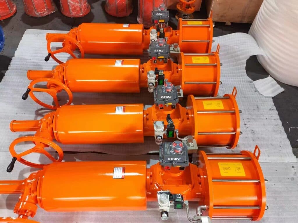
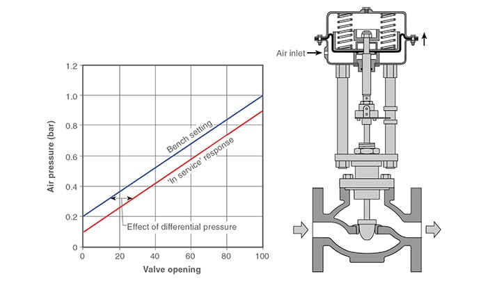
Pneumatic actuators are used in a wide variety of valves and are particularly well suited for service conditions requiring frequent operation and fast response. Depending on the system selected, these pneumatic actuated valves typically operate in the 2-10 bar range, with 4-6 bar air power being the most common. The compressed air supply is typically provided by an instrument air compressor package to ensure clean and dry air. There are two types of pneumatic actuators: piston type and diaphragm type. The piston type pneumatic actuator can have a long stroke, suitable for large size valves and its torque is relatively high compared to the diaphragm type. Most pneumatic piston type actuators will be used for valves that are operated on and off.
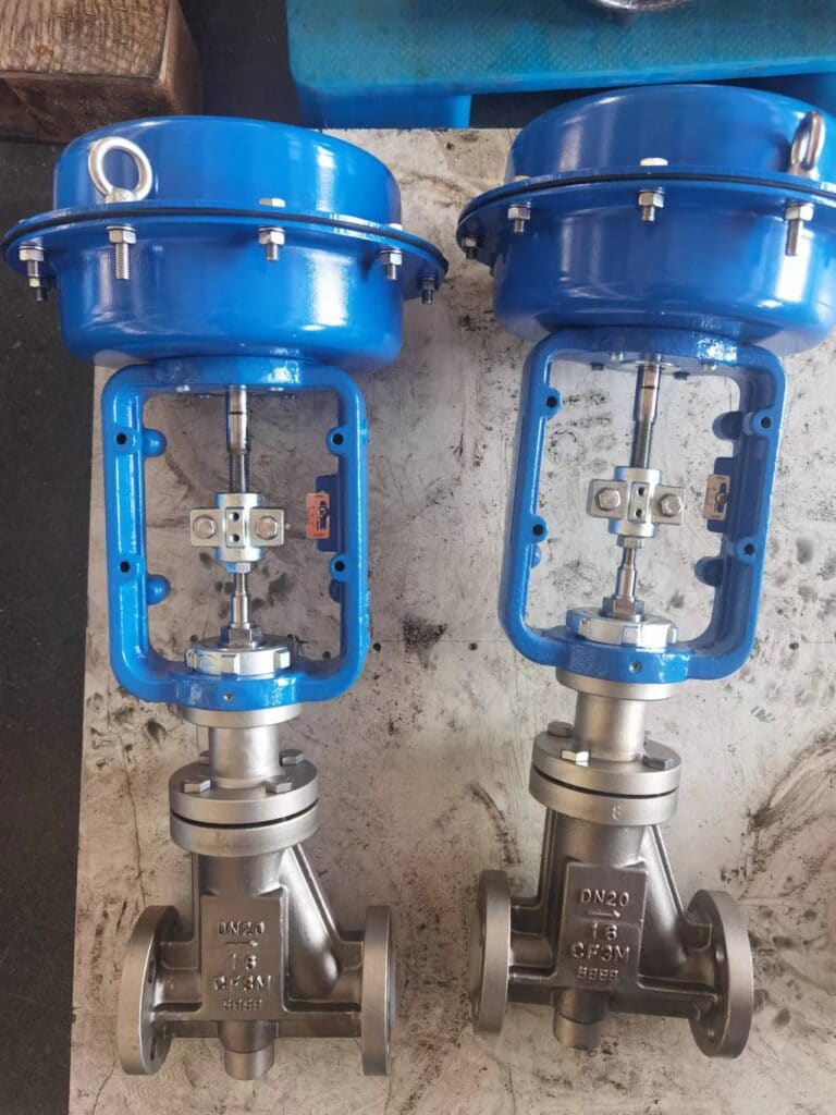
Diaphragm pneumatic actuators are usually suitable for regulating services, such as installation on control valves such as globe valves, eccentric plug valves, v-notch ball valves, butterfly valves, etc. However, their short stroke limits the size of valves that can be used. Pneumatic actuators are relatively large and require frequent maintenance because air can leak over time (especially with piston types), and diaphragm pneumatic types can suffer from diaphragm deterioration, among other problems.
Electric actuators are also often selected for valve operation, especially in power stations, where the use of electric valves tends to have the lowest total installed cost because field power is usually readily available and wiring and control instrumentation are relatively simple. However, with electric actuators that increase torque through large gear reducers, the response and action of the valve are often unwieldy and slow. Also, considering that power outages or electrical system failures are possible, we need to design an emergency plan for electric valves to ensure that the valves are safe in the event of a failure.
Hydraulic actuators are applied in less working conditions, but they are preferred for some special valves. Especially large size valves with high pressure which need frequent cyclic action to generate huge torque by hydraulic oil.
Valve Rating
The pressure rating of a valve indicates the ability of the valve to withstand pressure within a certain temperature range. The standard pressure ratings are well established, and we can refer to ratings in accordance with ASME/ANSI B16.34. The pressure rating is followed by the designation “WSP” for working steam pressure, and “WOG” for water, oil & gas. If a valve is used primarily for water service, a common designation is “WWP” or Water Working Pressure, indicating the ability to handle cold water.
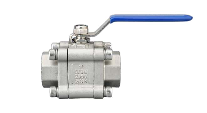
For example, 1000 WOG means 1000 psi pressure rating for water, oil, and gas. Class 300LB indicates a valve with a nominal pressure of 300 psig.
High temperature or high pressure service can cause a valve to have a lower pressure rating, and most industrial valves have temperature limits based on the capacity of the seat and trim material. Material selection is generally made by the working temperature but not pressure drop, so the suitability of the material is primarily based on temperature.
In some cases, the pressure drop must be kept to a minimum, and precise determination of the pressure drop through the valve is also necessary for the valve selection. Usually, we use the valve flow rate to measure the standard, the rated flow factor “Cv”, which indicates the flow rate through the valve at the maximum opening for a given pressure drop. Valve manufacturers usually determine this coefficient value by actual flow testing.
In Conclusion
When selecting chemical valves, the first factor to understand the chemical properties of the medium, and then the factors to consider are temperature and pressure. The properties, concentration, and temperature of the fluid are critical to the selection of corrosion-resistant materials. The valve body, plug, and operating components should be able to withstand the highest temperatures under continuous normal and transient operating conditions, as well as withstand the highest transient pressures expected. The final consideration is the degree to which the valve will shut off and should meet the field requirements for leakage. Manufacturers perform a bubble seal test before the valve leaves the factory, by testing the resilient seat of the valve for significant leakage. Other key parameters include flow speed, valve function (on/off or modulating), whether fire safety is required, and other additional functional requirements. Hope this article can help you a little about valve selection during chemical processing. Meanwhile if you are interested in more information about different types of control valves, you can read this article.
