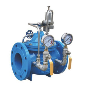
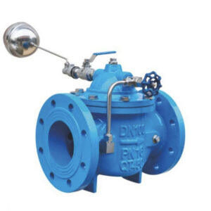
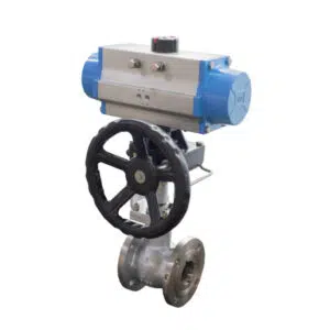
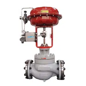
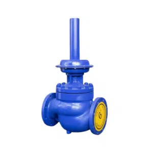
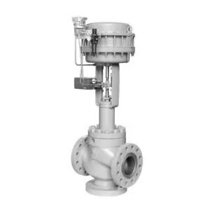
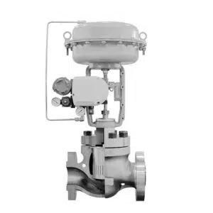
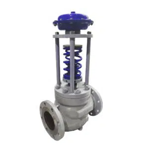
In the complex world of liquid piping systems, the secret weapons ensuring optimal performance are air release valves. These valves, including varieties like automatic air release valves and air/vacuum valves, play a pivotal role in maintaining efficiency. Acting as watchful guards, air valves automatically release entrapped air, preventing issues like headloss, flow reduction, and structural damage. In this blog we will dive into the workings of these essential components, exploring the diverse types, functions, and the crucial role they play in protecting liquid pipelines.
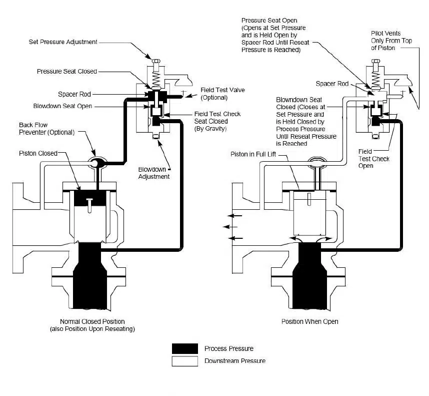
Function of Air Relief Valves
Significance in Preventing Inefficiencies
Air relief valves emerge as hidden protectors, keeping away inefficiencies that could plague liquid piping systems. Their crucial role lies in the efficient removal of trapped air and: wastewater gases, ensuring seamless operation. The consequences of neglecting trapped air—decreased water flow and heightened energy consumption for pumping—underscore the indispensable role of these valves in maintaining system efficiency.
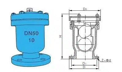
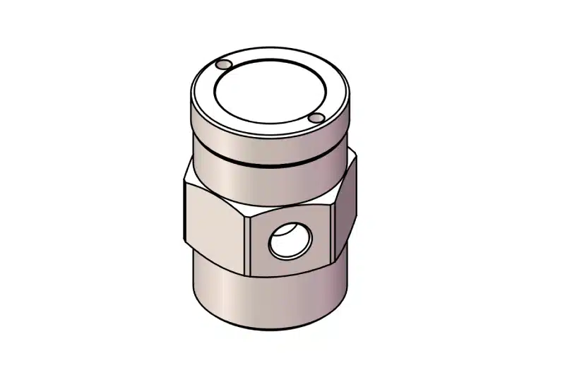
| DN(mm) | D (mm) | D1 (mm) | D2 (mm) | Φ (mm) | H (mm) |
| 15 | 95 | 65 | 45 | 135 | 210 |
| 20 | 105 | 75 | 55 | 135 | 210 |
| 25 | 115 | 85 | 65 | 135 | 210 |
| 40 | 145 | 115 | 85 | 150 | 210 |
| 50 | 160 | 125 | 100 | 150 | 210 |
| Note: This data is for reference only and is subject to the actual product. It is subject to change without prior notice. | |||||
Timely Removal of Trapped Air and Wastewater Gases
The efficiency of liquid piping systems hinges on the timely extraction of air and wastewater gases, a task diligently undertaken by air relief valves. As these valves automatically release accumulated air, they prevent issues like decreased water flow and increased energy consumption. Their strategic placement at key points in the pipeline, such as high points, long runs, and areas adjacent to mainline valves, ensures a continuous and smooth flow, mitigating potential inefficiencies.
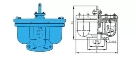
| Model | Size | Dimensions(mm) | ||||||
| D | D1 | D2 | L | Z-φd | Medium | Valve Body Material | ||
| TQB2-10 | 40 | 145 | 110 | 85 | 430 | 4-φ18 | Water | Cast Iron, Carbon Steel, Stainless Steel |
| TQB2-10 | 50 | 160 | 125 | 100 | 430 | 4-φ18 | Water | |
| TQB2-10 | 75 | 195 | 160 | 135 | 470 | 4-φ18 | Water | |
| TQB2-10 | 100 | 215 | 180 | 155 | 500 | 4-φ18 | Water | |
| TQB2-10 | 150 | 280 | 240 | 210 | 540 | 8-φ20 | Water | |
| TQB2-10 | 200 | 335 | 295 | 265 | 700 | 8-φ20 | Water | |
Types of Air Valves
i. Air-Release Valves
Air-release valves serve as the frontline defenders, automatically releasing air or gas at full operating pressure. Their mechanism, with small orifices, weighted floats, and leverage systems, ensures effective air expulsion during water entry. However, their limited orifice diameter restricts capacity for air intake and discharge.
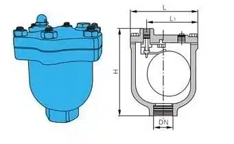
| DN(mm) | Inlet Size | Outlet Size | Vent Port(mm) | L x W x H(mm) |
| 15 | 1/2″(15m/m) | 1/4″ | 1.6 | 102 х 86 х 127 |
| 20 | 3/4″(20m/m) | 1/4″ | 1.6 | 102 х 86 х 127 |
| 25 | 1″(25m/m) | 1/4″ | 1.6 | 102 х 86 х 127 |
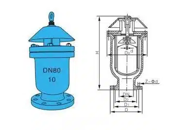
| DN | H | D | D1 | D2 | Z-Фd |
| mm | mm | mm | mm | mm | |
| 50 | 490 | 165 | 125 | 205 | 4-Ф18 |
| 80 | 590 | 200 | 135 | 270 | 8-Ф18 |
| 100 | 750 | 220 | 180 | 285 | 8-Ф18 |
| 150 | 820 | 285 | 240 | 340 | 8-Ф22 |
| 200 | 1000 | 340 | 295 | 400 | 8-Ф22 |
| 250 | 1200 | 395 | 350 | 465 | 12-Ф22 |
| Note: This data is for reference only and is subject to the actual product. It is subject to change without prior notice. | |||||
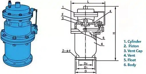
| Model | DN | D | D1 | D2 | Z-d | L | H |
| TTSP1.0 | 16,25,32,45,52 | 195 | 160 | 135 | 4-18 | 300 | 620 |
| 80 | 195 | 160 | 135 | 8-18 | 500 | 620 | |
| 100 | 215 | 180 | 155 | 8-18 | 500 | 620 | |
| 150 | 280 | 240 | 210 | 8-23 | 620 | 740 | |
| 200 | 340 | 295 | 266 | 8-23 | 620 | 780 | |
| 250 | 395 | 350 | 319 | 12-23 | 620 | 820 | |
| 300 | 445 | 400 | 370 | 12-23 | 620 | 850 | |
| 400 | 565 | 515 | 480 | 16-25 | 700 | 910 |
ii. Air/Vacuum Valves
Air/vacuum valves boast a full-size orifice, ranging from half an inch to 20 inches, allowing efficient release of large air volumes during pump startup. They play a critical role in preventing vacuum conditions in pipelines and aiding in drainage. These valves, normally open, automatically shut off as water levels rise, maintaining optimal system conditions.
Need for Air Valves
Dissolved Air and Gases in Water
Water naturally contains around 2% dissolved air or gases under standard conditions. In wastewater systems, this percentage increases due to the decomposition of waste matter. Understanding the presence of these elements is crucial for effective air valve implementation.
Factors Leading to Accumulation
Changes in pressure, temperature fluctuations, and the decomposition of waste matter contribute to the constant dissolution and release of air and gases. These elements, once released, tend to accumulate in high points of the piping system, forming air pockets.
Consequences of Air Pockets in Liquid Piping Systems
Air pockets in liquid piping systems can have far-reaching consequences. They increase headloss, reduce flow rates, interrupt water supply, amplify surge pressures, cause structural damage to pipes, decrease pump efficiency, promote corrosion, and result in increased energy costs. Recognizing these consequences emphasizes the critical role of air valves in maintaining system efficiency.
Applications of Air Valves in Water Systems
Strategic Placement for Optimal Performance
Automatic air release valves, including combination air valves, are strategically placed along pipelines to ensure the smooth and efficient operation of water systems. These valves, such as the automatic air release valve, play a crucial role in maintaining system integrity by effectively exhausting air pockets and preventing disruptions in the flow of water.
AWWA Recommendations for Enhanced Functionality
Following American Water Works Association (AWWA) standards, these valves are recommended at key locations within the pipeline, including high points, long horizontal runs, descents, ascents, positions adjacent to mainline valves, downstream of pumps, and areas with changes in slope. This placement adheres to industry guidelines and enhances the overall effectiveness of air release valves in water systems, ensuring optimal performance and preventing disruptions caused by air pockets.
Working Mechanism of Air Relief Valves
Air relief valves, also known as air release valves, are used in piping systems to automatically release trapped air or gas. These valves are crucial for the efficient operation and protection of the system. Here’s how they work:
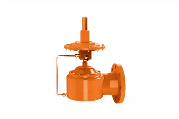
The working principle of the air compressor pressure relief valve is very simple. It is composed of a spring and a valve plug. When the compressed air line pressure exceeds the set value, the spring is compressed and the valve plug moves upward, thereby opening the valve and releasing excess air. When the pressure drops below the set value, the spring returns to its original position and the plug closes the valve and stops releasing air.
The set pressure of the air compressor pressure relief valve is determined based on the rated pressure of the air compressor and the usage requirements of the pipeline. Under normal operating conditions, the air compressor pressure relief valve is usually closed. Only when the pipeline pressure is too high, the pressure relief valve will automatically open to release excess air. The design and installation of the pressure relief valve should pay attention to the direction and flow rate of air to ensure its normal operation.
When using an air compressor pressure relief valve, regular inspection and maintenance are required to ensure its well operation. The inspection content includes: whether the sealing performance and spring elasticity of the pressure relief valve are regular working, and whether the valve and pipeline are damaged or worn. If the pressure relief valve is found to be malfunctioning or unable to close properly, it should be replaced or repaired in time.
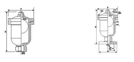
Threaded Ends Air Relief Valve NPT
| DN(mm) | ZG | Φ | H |
| 15 | 1/2″ | 135 | 205 |
| 20 | 3/4″ | 135 | 205 |
| 25 | 1″ | 135 | 205 |
| 40 | 11/2 | 150 | 205 |
| 50 | 2″ | 150 | 205 |
Flanged Ends Air Relief Valve RF/FF
| DN(mm) | D | D1 | D2 | Φ | H |
| 15 | 95 | 65 | 45 | 135 | 210 |
| 20 | 105 | 75 | 55 | 135 | 210 |
| 25 | 115 | 85 | 65 | 135 | 210 |
| 40 | 140 | 115 | 80 | 150 | 210 |
| 150 | 160 | 125 | 100 | 150 | 210 |
Location and Purpose
Air relief valves are typically installed at high points in a piping system where air naturally accumulates. Their primary purpose is to release trapped air that collects at these points, which can otherwise lead to inefficiencies, flow obstruction, increased pressure, or even system failure.
Automatic Operation
The valve operates automatically. It is designed to sense the difference between air (or gas) and liquid within the system.
Internal Float Mechanism
Most air relief valves use a float mechanism. When there is no air present, the liquid in the system lifts the float, which in turn keeps the valve closed.
Accumulation of Air
As air accumulates in the system and enters the valve, the water level inside the valve drops, causing the float to descend.
Valve Opening
The descending float opens a small orifice or vent, allowing the accumulated air to escape. This is typically a passive process, meaning it relies on the natural buoyancy of the float and doesn’t require external energy.
Valve Closing
Once the air is released and liquid begins to fill the valve again, the float rises, closing the orifice and preventing the liquid from escaping.
Continuous Operation
This cycle of opening and closing continues automatically as air accumulates and is released, ensuring that the system remains efficient and protected from the problems that trapped air can cause, such as water hammer, corrosion, and reduced flow capacity.
Different Types for Different Needs
There are various types of air relief valves designed for specific needs:
i. Small Orifice Valves
Designed to release small amounts of air continuously during normal system operation.
ii. Large Orifice Valves
Used to release large volumes of air when a system is filled, and to allow air back into the system when it is drained.
iii. Combination Valves
Incorporate both small and large orifices to handle air release under both operational and transient conditions.
Importance of Air Valves in Preventing Issues
Mitigating Headloss and Enhancing
Flow Air release valves, including the automatic air release valve, play a pivotal role in mitigating headloss and enhancing the flow rate within liquid piping systems. By efficiently releasing trapped air and gases, these valves contribute to the reduction of headloss ensuring an uninterrupted and optimal flow of water. The design of the valve body further facilitates their ability to exhaust air, promoting smooth and efficient system operation.
Ensuring Continuous Water Supply
The strategic placement and operation of air valves, such as the automatic air release valve, are crucial in preventing interruptions in water supply. These valves work diligently to eliminate air pockets that could otherwise impede the consistent delivery of water, ensuring a continuous and reliable water supply. The valve body’s design is tailored to address air pocket concerns, ensuring a reliable and efficient water distribution system.
Safeguarding Against
Surge Pressure and Structural Damage Automatic air release valves play an important role in the overall integrity of water systems by addressing issues related to surge pressure and potential structural damage. Their role in preventing air-related surges helps safeguard the structural components of pipes, pumps, and other system elements, ensuring the longevity and efficiency of the entire water distribution system. The exhaust of air from the system is a critical function of these valves, minimizing the risk of structural damage due to excessive pressure and promoting a secure and reliable water infrastructure.
Summary
In conclusion, air relief valves, particularly automatic air release valves, play a crucial role in liquid piping systems by efficiently releasing trapped air and ensuring smooth operation. Their strategic placement prevents interruptions in water supply, safeguards against surge pressure, and enhances the overall integrity of the system. Recognizing the importance of these valves is essential for maintaining optimal flow, preventing inefficiencies, and ensuring the longevity of liquid piping systems. Please do not hesitate to contact us if you have any questions about air relief valves. THINKTANK‘s engineers always be here to happy serve you.


