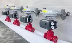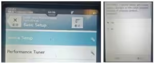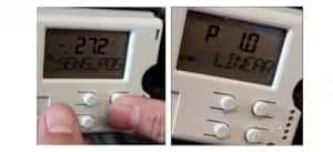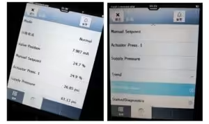
This quick guide explains how to perform an automatic travel calibration of a Fisher FIELDVUE DVC6200 digital valve controller using an Emerson AMS Trex communicator.
Before You Start
Make sure that:
- The DVC6200 is correctly mounted on the actuator.
- The travel feedback linkage or magnetic array is correctly installed.
- Instrument air and the 4–20 mA signal are available.
- The actuator and relay configuration are correct.
- The valve can safely move through its full travel.
Warning: Auto calibration moves the valve through its full stroke. Isolate the valve from the process and release or equalize process pressure before starting.
DVC6200 Auto Calibration Procedure
| Step | Procedure |
|---|---|
| 1. Connect the AMS Trex | Connect the Trex HART leads to the DVC6200 signal terminals or to a suitable HART connection point in the 4–20 mA loop. |
| 2. Connect to the Positioner | Select HART on the Trex and tap Connect. Select the DVC6200 and enter the Online menu. |
| 3. Check the Valve and Actuator Setup | Go to Configure → Manual Setup → Valve and Actuator. Confirm the actuator type, travel sensor motion, valve action and installed relay type. |
| 4. Place the DVC6200 Out of Service | Go to Configure → Manual Setup → Mode and Protection → Change Instrument Mode. Select Out of Service and confirm. Set instrument protection to None when required. The DVC6200 must be Out of Service and unprotected before communicator-based calibration. |
| 5. Open Auto Travel Calibration | Go to Configure → Calibration → Travel Calibration → Auto Calibration. Menu wording may differ slightly depending on the HART and device-description version. |
| 6. Start the Calibration | Follow the instructions displayed on the Trex. Confirm that the valve is safe to stroke, then start the calibration. The DVC6200 will move the valve through its travel range and determine the calibrated travel limits. |
| 7. Complete Relay Adjustment, If Requested | For a double-acting actuator using Relay A, the Trex may ask whether relay adjustment should be performed. Follow the on-screen instructions or select No to continue when the relay has already been correctly adjusted. |
| 8. Confirm the Calibration Result | Wait until the Trex reports that auto calibration has been completed successfully. Select OK or Done to exit the calibration procedure. |
| 9. Return the Positioner to Service | Go to Mode and Protection → Change Instrument Mode and select In Service. This allows the DVC6200 to resume normal control from the 4–20 mA input signal. |
| 10. Verify Valve Operation | Apply several input signals, such as 0%, 25%, 50%, 75% and 100%. Confirm that the actual valve travel follows the commanded position and that no active calibration or travel alerts remain. |
Relay Type Selection
The relay setting entered in the Trex must match the relay physically installed in the DVC6200.
| Relay Type | Application |
|---|---|
| Relay A | Double-acting actuators or single-acting direct applications |
| Relay B | Single-acting reverse applications |
| Relay C | Single-acting direct applications |
For a single-acting direct configuration, actuator pressure is connected to Output A. For a single-acting reverse configuration using Relay B, actuator pressure is connected to Output B.
Important: Do not select Relay A, B or C only according to the required fail-open or fail-close action. Check the relay label, pneumatic output connection and actuator configuration before calibration.
Checking the Last Calibration Result
To review the previous automatic calibration result, go to:
Configure → Calibration → Travel Calibration → Last AutoCal Status
The calibration menu may also include:
- Manual Calibration
- Calibration Record
- Calibration Type
- Calibration Time
- Calibrator
Available items depend on the DVC6200 HART version and device configuration.
Common Calibration Problems
Auto Calibration Does Not Start
Check whether:
- Instrument Mode is set to Out of Service.
- Instrument protection is set to None.
- The DVC6200 has sufficient loop current.
- HART communication is stable.
- Supply air pressure is sufficient.
- The valve is free to move.
Valve Moves in the Wrong Direction
Check:
- Relay type.
- Output A or Output B tubing connection.
- Actuator type.
- Travel sensor motion setting.
- Zero-power condition.
- Valve opening direction.
Calibration Fails Before Reaching Full Travel
Possible causes include:
- Insufficient supply pressure.
- Incorrect actuator size or spring range.
- Mechanical obstruction.
- Excessive valve friction.
- Incorrect feedback installation.
- Travel sensor moving outside its valid range.
- Incorrect relay adjustment.
Quick Menu Path
Connect → Online → Configure → Manual Setup → Mode and Protection → Out of Service
Then:
Configure → Calibration → Travel Calibration → Auto Calibration
After calibration:
Mode and Protection → In Service
After returning the instrument to service, verify positioner error and deadband against the project’s calibration criteria; a completed Auto Calibration status alone does not confirm full positioning performance.