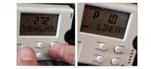
This guide explains how to configure and automatically initialize a CHUANYI HVP3 smart valve positioner using the local three-button interface.
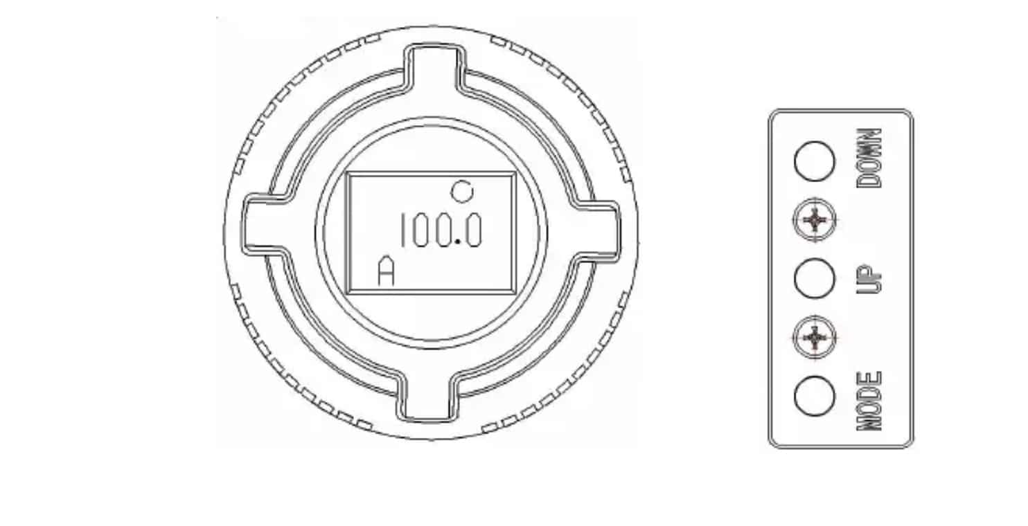
Button Functions
| Button | Function |
|---|---|
| MODE | Confirm a selection, switch operating modes, or enter and exit a special function |
| UP | Move upward through the menu, increase a value, or move the valve in manual mode |
| DOWN | Move downward through the menu, decrease a value, or move the valve in manual mode |
A short press means pressing a button for less than four seconds. A long press means pressing and holding it for more than four seconds.
Unlocking the Keypad
When the lock symbol appears in the upper-right corner of the display:
- Press UP and DOWN simultaneously.
- Hold both buttons for approximately one second.
- Release the buttons when the keypad is unlocked.
The positioner will not respond to normal button commands while the keypad is locked.
Before Calibration
Confirm that:
- The positioner is correctly mounted.
- The feedback lever or rotary coupling is correctly installed.
- The pneumatic tubing is correctly connected.
- Clean and sufficient instrument air is available.
- The electrical input signal is connected.
- The valve can safely travel through its full operating range.
- The
YFCTactuator setting is correct.
Warning: Automatic initialization moves the valve through its operating range. Isolate the valve from the process before starting.
Recommended One-Touch Auto Calibration
The one-touch method is the fastest commissioning procedure for the HVP3.
| Step | Procedure |
|---|---|
| 1. Confirm the Actuator Type | Check that YFCT is set to Lin for a linear actuator or nLin for a rotary actuator. |
| 2. Select Automatic Mode | Make sure the display shows AUTO. Briefly press MODE to switch between automatic and manual modes when required. |
| 3. Set the Input Current | Apply an input signal of 10.0 ± 0.1 mA. |
| 4. Start Initialization | Press and hold the DOWN button for more than four seconds. |
| 5. Wait for Completion | The positioner automatically detects the valve travel and control parameters. The procedure normally takes approximately three to six minutes. |
| 6. Return to Operation | After successful initialization, the positioner automatically returns to normal automatic control. |
| 7. Verify Valve Travel | Apply several input signals and confirm that the valve moves in the required direction and reaches both end positions. |
According to the HVP3 manual, the one-touch initialization method requires automatic mode and a control current within 10.0 ± 0.1 mA. Moving the valve manually to 50% is not specified as part of this method.
Calibration Through the AUTE Menu
Use this method when the mechanical feedback installation needs to be checked before initialization.
Step 1: Enter the Function Menu
- Press and hold MODE.
- Wait until the function-selection menu appears.
- Use UP or DOWN to select:
3 AUTE
- Briefly press MODE to enter the initialization function.
The main function menu includes 1 CONF, 2 ANSH, 3 AUTE, 4 FBCA and RET.
Step 2: Check the Mechanical Feedback Range
Linear Actuator
Use UP and DOWN to move the valve between its fully closed and fully open positions.
The total feedback-shaft rotation should be:
25° to 70°
When the measured angle is below 25° or above 70°, adjust the sliding pin position on the feedback lever.
Rotary Actuator
Use DOWN to move the valve to its fully closed position.
The displayed feedback angle at the closed position should normally be:
−40° to −60°
When it is outside this range, adjust the rotary feedback coupling.
Step 3: Start Initialization
After completing the installation-position check:
- Briefly press MODE three times.
- Wait while the positioner performs automatic initialization.
- Do not interrupt the air supply or input signal.
- Wait until the display indicates that initialization is complete.
- Press and hold MODE to return to automatic control.
Initialization normally requires approximately three to six minutes.
Parameter Configuration
Entering the Configuration Menu
- Press and hold MODE.
- Select
1 CONFusing UP or DOWN. - Briefly press MODE to enter parameter configuration.
- Use UP or DOWN to select a parameter.
- Briefly press MODE. The current setting flashes.
- Use UP or DOWN to change the setting.
- Briefly press MODE again to confirm.
- Press and hold MODE to return to automatic control.
Main Configuration Parameters
| No. | Parameter | Available Settings | Function |
|---|---|---|---|
| 1 | YFCT | Lin, nLin | Selects linear or rotary actuator feedback |
| 2 | SDIR | riSE, FALL | Sets the relationship between the input signal and commanded position |
| 3 | YDIR | riSE, FALL | Sets the direction of the LCD position indication |
| 4 | SFCT | Lin, 1:50, 50:1, FrEE | Selects linear, equal-percentage, quick-opening or custom characterization |
| 5 | AFCT | OFF, ON, LASt, POS | Selects the positioner response to a detected control fault |
| 6 | MA4 | 3.8–20.0 mA | Sets the lower input-signal limit |
| 7 | MA20 | 3.8–20.0 mA | Sets the upper input-signal limit |
| 8 | DEBA | Auto, 0.1–10% | Sets the positioner deadband |
| 9 | SPRA | 0–25% | Sets the lower travel limit |
| 10 | SPRE | 75–100% | Sets the upper travel limit |
| 11 | SCUA | 0–100% | Sets the lower signal cut-off point |
| 12 | SCUE | 0–100% | Sets the upper signal cut-off point |
| 13 | SHUT | 0–100% | Sets the shutoff threshold |
| 14 | YCLS | ALL, UP, dN, NO | Selects pneumatic tight shutoff at both ends, upper end, lower end or neither end |
| 15 | DEFT | YES, NO | Restores the factory settings |
| 16 | RET | — | Returns to the previous menu |
The standard factory settings include YFCT = Lin, SDIR = riSE, YDIR = riSE, SFCT = Lin, MA4 = 4 mA, MA20 = 20 mA, DEBA = 0.4%, SPRA = 0% and SPRE = 100%.
Actuator Type — YFCT
| Setting | Application |
|---|---|
| Lin | Linear-stroke actuator |
| nLin | Rotary or part-turn actuator |
For globe control valves with a conventional feedback lever, select:
YFCT = Lin
For ball valves, butterfly valves and other part-turn valves, select:
YFCT = nLin
Important:
YFCTmust match the actual mounting arrangement. Using a linear setting on a rotary installation may prevent successful initialization. Using a rotary setting on an incompatible linear installation may damage the positioner’s mechanical feedback assembly.
Input Signal Direction — SDIR
The SDIR parameter determines how the commanded valve position changes as the input signal increases.
| Setting | 4 mA | 20 mA |
|---|---|---|
| riSE | 0% | 100% |
| FALL | 100% | 0% |
When 0% is defined as valve closed:
SDIR = riSE
- 4 mA = valve closed
- 20 mA = valve open
SDIR = FALL
- 4 mA = valve open
- 20 mA = valve closed
SDIR does not determine the mechanical fail-open or fail-close position. The actual fail position also depends on the actuator spring direction and pneumatic arrangement. The parameter only reverses the relationship between the electrical input signal and the commanded position.
Display Direction — YDIR
The YDIR parameter controls how actual valve travel is shown on the LCD.
| Setting | Actual Travel | LCD Indication |
|---|---|---|
| riSE | 0% → 100% | 0% → 100% |
| FALL | 0% → 100% | 100% → 0% |
Changing YDIR reverses the position display. It does not reverse the actual relationship between the 4–20 mA input and the valve movement. Use SDIR to reverse the control direction.
Output Characterization — SFCT
| Setting | Characteristic |
|---|---|
| Lin | Linear |
| 1:50 | Equal-percentage or logarithmic |
| 50:1 | Quick-opening |
| FrEE | User-defined characteristic |
For normal initial commissioning, select:
SFCT = Lin
When FrEE is selected, the output characteristic can be configured through a 21-point table from 0% to 100%.
Fault Response — AFCT
| Setting | Electronic Fault Response |
|---|---|
| OFF | Move toward the 0% position |
| ON | Move toward the 100% position |
| LASt | Hold the last controlled position |
| POS | Move to a manually specified position |
This parameter controls the response to a detected electronic or control fault. It should not be treated as the only definition of the valve’s fail-safe position because loss of instrument air is governed by the actuator and pneumatic configuration.
Automatic and Manual Modes
Briefly press MODE to switch between:
AUTO— the valve follows the incoming control signalMAN— the valve can be moved locally with UP and DOWN
In manual mode:
- Press UP to increase the valve position.
- Press DOWN to decrease the valve position.
In automatic mode:
- Press DOWN to display the current input signal.
- Press UP to review temperature information.
Factory Reset
Use factory reset only when the existing configuration is no longer suitable.
- Press and hold MODE.
- Select
1 CONF. - Briefly press MODE.
- Use UP or DOWN to select
15 DEFT. - Briefly press MODE until the setting flashes.
- Select
YES. - Briefly press MODE to confirm.
- Verify
YFCTand all required project settings. - Perform a new automatic initialization.
Factory reset restores the configured parameters to their default values, so the positioner must be checked and recalibrated before being returned to service.
Final Function Check
After initialization, apply the following input signals:
| Input Signal | Expected Position with SDIR = riSE |
|---|---|
| 4 mA | 0% |
| 8 mA | 25% |
| 12 mA | 50% |
| 16 mA | 75% |
| 20 mA | 100% |
Confirm that:
- The valve moves in the correct direction.
- The displayed position agrees with the actual valve position.
- The valve reaches both end positions.
- Valve movement is smooth and stable.
- The positioner returns to
AUTO. - No active alarm code remains.
Quick Setup Sequence
For most standard linear control valves:
Unlock keypad → YFCT: Lin → AUTO mode → Input: 10.0 ± 0.1 mA → Hold DOWN → Wait 3–6 minutes → Verify 4–20 mA travel
For most rotary control valves:
Unlock keypad → YFCT: nLin → AUTO mode → Input: 10.0 ± 0.1 mA → Hold DOWN → Wait 3–6 minutes → Verify rotation