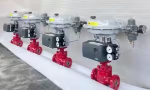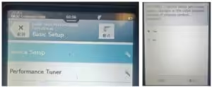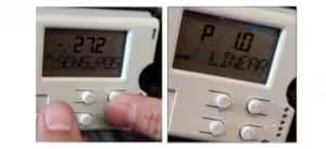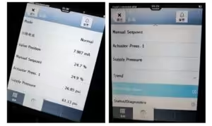
This guide explains how to perform automatic setup on an Azbil Smart Valve Positioner 300 Series, including models AVP300, AVP301 and AVP302.
The same basic procedure also applies to the corresponding remote-mounted AVP200 Series models.
Before Auto-Setup
Confirm that:
- The positioner is correctly mounted on the actuator.
- The feedback lever and connecting pin are securely installed.
- At approximately 50% valve travel, the feedback lever is close to horizontal.
- Pneumatic tubing is connected correctly.
- Clean instrument air is available.
- The electrical input signal is connected.
- The internal A/M switch is set to AUTO.
- The valve can safely travel through its complete stroke.
Warning: Auto-setup moves the valve from fully closed to fully open. Isolate the valve from the process and keep clear of moving parts before starting.
Auto-Setup Procedure
| Step | Procedure |
|---|---|
| 1. Confirm the Valve Action | Confirm that the configured valve action matches the actual valve, actuator and feedback-lever movement. Incorrect valve-action settings may cause reversed operation or incorrect zero and span values. |
| 2. Apply the Input Signal | Set the input signal to 18 ± 1 mA DC. |
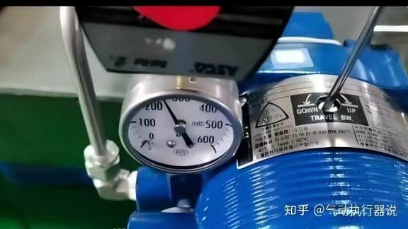
| 3. Start Auto-Setup | Insert a non-magnetic flat-blade screwdriver into the external zero/span adjustment switch. Rotate the switch 90° clockwise toward UP and hold it for approximately three seconds. |
| 4. Release the Switch | When the valve begins moving in the direction that releases actuator air pressure, release the switch and remove the screwdriver. |
| 5. Wait for Auto-Setup | The valve automatically moves between fully closed and fully open two times. It then moves to approximately 50% travel. The complete procedure normally takes about three to four minutes. |
| 6. Save the Settings | When the valve begins responding normally to the input signal, auto-setup is complete. Keep the input signal at 4 mA or higher for at least 30 seconds so the settings are saved in non-volatile memory. |
| 7. Verify Valve Operation | Change the input signal through several points and confirm that the valve position follows the command correctly. |
This process automatically determines the valve zero and span, actuator direction, input range, actuator-size control parameters and packing-friction characteristics.
Standard UP Direction
For standard AVP300, AVP301 and AVP302 installations:
Turn the adjustment switch clockwise to UP and hold for approximately three seconds.
Do not describe the procedure as:
Select UP for air-to-open and DOWN for air-to-close.
That rule is incorrect. The switch direction used to initiate auto-setup is not selected solely according to whether the valve is air-to-open or air-to-close.
When Is the DOWN Direction Used?
The counterclockwise DOWN direction is a special procedure used for specific Azbil VFR control valves equipped with VR or RSA actuators.
For most standard linear and rotary control-valve installations, use:
UP — clockwise
For a special VFR valve with the applicable VR or RSA actuator, use:
DOWN — counterclockwise
Important: Do not use DOWN only because the actuator is air-to-close. Confirm the valve and actuator model before using the special DOWN procedure.
Valve Action Configuration
The configured valve action must match the actual feedback-lever movement.
| Valve Movement | Feedback-Lever Movement | Valve Action Setting |
|---|---|---|
| Closed to open | Lever moves downward | Reverse |
| Open to closed | Lever moves downward | Direct |
For a reverse-close arrangement, where the fully closed valve position is at the upper end of the actuator travel, configure the valve action correctly before starting auto-setup.
Auto-setup detects actuator action, but the valve-action parameter should be checked beforehand to prevent reversed zero and span settings.
What Happens During Auto-Setup?
During the procedure, the positioner automatically:
- Detects the fully closed position.
- Detects the fully open position.
- Adjusts zero and span.
- Determines actuator operation.
- Sets the 4–20 mA input direction.
- Selects an actuator-size control parameter.
- Estimates valve-packing hysteresis.
- Moves the valve close to 50% travel.
- Returns control to the external input signal.
The valve does not need to be manually held at 50%. The movement to approximately 50% is part of the automatic sequence.
Final Function Check
After auto-setup, apply the following input signals:
| Input Signal | Expected Valve Position* |
|---|---|
| 4 mA | 0% |
| 8 mA | 25% |
| 12 mA | 50% |
| 16 mA | 75% |
| 20 mA | 100% |
*This example applies when 4 mA is configured as the closed position and 20 mA as the open position.
Confirm that:
- The valve moves in the correct direction.
- The valve reaches its fully closed and fully open positions.
- The response is smooth and stable.
- The valve position corresponds to the input signal.
- The feedback lever does not contact the positioner body or mounting bracket.
- No hunting or continuous oscillation occurs.
Pressure-Gauge Check
The supply-pressure and output-pressure gauges do not need to display the same pressure.
The output pressure changes according to:
- The input signal
- Valve position
- Actuator spring load
- Process force
- Valve friction
Use the gauges to confirm that supply air is available and that the output pressure changes normally. Do not adjust the positioner merely to make both gauge readings equal.
If Auto-Setup Does Not Start
Check the following:
- Input signal is within 18 ± 1 mA.
- The A/M switch is set to AUTO.
- Supply air pressure is sufficient.
- Pneumatic tubing is connected correctly.
- The electronics module is properly seated.
- The screwdriver is not magnetic.
- The external adjustment switch is held for approximately three seconds.
- The valve is mechanically free to move.
Azbil specifically warns that a magnetic screwdriver may interfere with operation of the external adjustment switch.
If the Valve Hunts After Auto-Setup
Possible causes include:
- Incorrect actuator-size parameter
- Excessive booster-relay sensitivity
- Incorrect packing-friction setting
- Air leakage
- Excessive valve friction
- Incorrect feedback-lever geometry
- Speed controllers restricting the air line
When a speed controller is installed, open it fully before running auto-setup. Adjust the valve speed only after auto-setup has finished.
Quick Setup Sequence
Check mounting and valve action → Set A/M switch to AUTO → Apply 18 ± 1 mA → Turn switch clockwise to UP → Hold 3 seconds → Wait 3–4 minutes → Keep signal above 4 mA for 30 seconds → Verify 4–20 mA travel