High-Pressure Hydrogen Control, Liquid-Ammonia Letdown, FAT and Repeat-Build Valve Packages
A modular ammonia synthesis unit does not need a collection of unrelated valve quotations.
It needs a coordinated valve package in which every included valve tag has a defined:
- Process duty;
- Pressure boundary;
- Flow and control requirement;
- Material specification;
- Actuator configuration;
- Inspection method;
- Documentation requirement.
This is especially important for pilot plants, catalyst test units and repeat-build modular process skids.
A valve may appear small on a preliminary valve list but still be responsible for:
- Controlling an extremely low flow of hydrogen-rich gas at high pressure;
- Maintaining the hydrogen-to-nitrogen feed ratio;
- Reducing liquid-ammonia pressure into a lower-pressure separator;
- Isolating high-pressure process inventory;
- Depressurizing part of the unit during a shutdown event;
- Protecting a compact skid from leakage, vibration or integration problems.
The most important engineering question is therefore not:
Which standard valve model matches the line size and pressure class?
The more useful question is:
How should each valve tag be selected, documented, integrated and tested so that the first module can be manufactured successfully and the approved configuration can be repeated on future modules?
THINKTANK can begin this review from a preliminary valve list, selected P&ID extracts or tag-specific datasheets. A complete proprietary process package is not normally required during the initial stage.
From this information, we can identify the highest-risk valve tags, issue technical clarifications, prepare preliminary constructions for budget pricing and establish a route to final sizing, drawings, FAT and repeat-build production.
Three Valve Problems That Commonly Create Disproportionate Risk
In a modular ammonia unit, three valve duties deserve particular attention.
1. An Oversized High-Pressure Hydrogen Control Valve
A DN6 or DN10 connection does not mean the valve requires a standard DN6 or DN10 control trim.
When the required Cv is extremely small, a conventional trim may operate close to the seat, where packing friction, stem tolerances, positioner resolution and pneumatic deadband can dominate the valve response.
The result may be:
- Poor low-flow resolution;
- Unstable hydrogen-to-nitrogen ratio control;
- Stick-slip movement;
- Excessive sensitivity to friction;
- Inability to reproduce the required test condition.
2. A Liquid-Ammonia Valve Selected Without a Flashing Review
A liquid-ammonia valve cannot be selected from upstream pressure alone.
The downstream pressure, inlet temperature, liquid subcooling and receiving-vessel condition determine whether the fluid:
- Remains liquid;
- Experiences cavitation and pressure recovery;
- Begins vaporizing inside the valve;
- Leaves the valve as a flashing two-phase stream.
A generic “anti-cavitation trim” does not solve a genuinely flashing application.
3. An Actuator Sized from a Bench Stroke Test
A valve that strokes successfully at atmospheric pressure may still fail to close or seat against the actual process differential pressure.
Actuator sizing must consider:
- Maximum shut-off differential pressure;
- Required fail action;
- Seat and packing forces;
- Available air-supply pressure;
- Required stroking time;
- Engineering safety margin.
These are not minor details. They can determine whether the completed module passes FAT and whether it performs correctly after installation.
Valve Systems Commonly Included within the Agreed Module Boundary
A pilot-scale catalyst test unit, demonstration skid and commercial modular ammonia plant do not necessarily contain the same process sections.
The final valve scope must therefore be based on the customer’s valve list and agreed module boundary.
| Process area | Typical valve duties | Typical valve categories | Main engineering questions |
|---|---|---|---|
| Hydrogen feed | Flow control, pressure reduction, isolation and reverse-flow prevention | Low-Cv control valves, regulators, isolation valves and check valves | What are the minimum, normal and maximum flows? Can stable control be achieved at low travel? |
| Nitrogen feed | Flow control, ratio control, isolation and purging | Control valves, regulators, isolation valves and check valves | How accurately must the H₂-to-N₂ ratio be maintained? |
| Feed compression, where included | Compressor isolation, recycle, bypass and depressurization | Automated isolation valves, recycle valves, check valves and blowdown valves | What differential pressure exists during start-up, trip and shutdown? |
| Reactor or catalyst-test section | Feed distribution, isolation, bypass, sampling and purging | High-pressure control valves, block valves, needle valves and sample valves | Will the unit operate under multiple test conditions or catalyst campaigns? |
| Synthesis-gas recycle, where included | Recycle control, purge control and inert removal | Control valves, low-Cv purge valves, isolation valves and check valves | Which operating case governs the valve sizing? |
| Ammonia condensation and separation | Separator level control, liquid letdown, drain and isolation | Level control valves, angle valves, isolation valves and check valves | Will liquid ammonia flash across the valve? |
| Product-ammonia section | Transfer, pressure reduction, isolation and emergency shutdown | Control valves, ESD valves, block valves and check valves | What phase and temperature will exist downstream? |
| Nitrogen and argon utilities | Inerting, purging, analyser service and testing | Regulators, micro-flow valves, solenoid valves and needle valves | Is the required flow too low for a standard trim? |
| Instrument air | Actuator supply and pneumatic control | Filter regulators, solenoid valves and isolation valves | Is sufficient air pressure and flow available during valve movement? |
| Vent, drain and sampling | Controlled depressurization, draining and maintenance isolation | Blowdown valves, needle valves, root valves and double-block arrangements | Where will released ammonia, hydrogen or two-phase fluid be routed? |
| Pressure protection | Overpressure and trapped-liquid thermal protection | Safety valves and thermal relief valves | Has the governing relief basis been provided by the responsible process designer? |
| Emergency shutdown | Isolation of hazardous process inventory | Automated ball, globe or butterfly valves | What fail action, shut-off differential pressure and stroking time are required? |
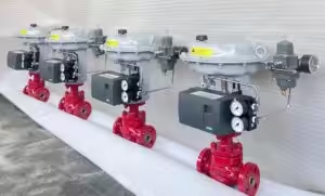
A coordinated package may therefore include control valves, automated on-off valves, manual isolation valves, check valves, regulators, safety valves, thermal relief valves, solenoid valves and valve-mounted accessories.
It does not mean that the valve supplier automatically assumes responsibility for every valve, piping component or process function within the complete skid.
Pilot Plants and Repeat-Build Modules Have Different Valve Priorities
A pilot-scale ammonia unit is not simply a smaller commercial plant.
Pilot plants and catalyst test units may operate across a wide experimental range. Process engineers may change pressure, flow, temperature, gas composition, catalyst loading or recycle conditions between campaigns.
A commercial repeat-build module normally has a more clearly defined operating envelope but places greater emphasis on reliability, availability, standardization and lifecycle cost.
| Engineering consideration | Pilot plant or catalyst-test unit | Commercial repeat-build module |
| Operating envelope | Wide and frequently adjusted | More clearly defined |
| Minimum flow | May be extremely low | Usually more predictable |
| Turndown | Frequently critical | Important but more stable |
| Start-stop cycles | Potentially frequent | Based on the operating philosophy |
| Trim flexibility | Interchangeable micro-flow trims may be valuable | Standardized trim codes are preferred |
| Sampling points | Often extensive | More limited and standardized |
| Instrumentation | Optimized for data collection | Optimized for dependable operation |
| Design changes | Expected during development | Controlled after design freeze |
| Spare parts | May require interchangeable trims | Common spares across multiple modules |
| Acceptance testing | May simulate different operating modes | Should follow a repeatable FAT procedure |
| Documentation | Must preserve experimental changes | Must preserve the repeat-build baseline |
For a pilot unit, the valve package should provide flexibility without creating uncontrolled variation.
For repeat-build production, the objective should be to freeze an approved valve architecture covering:
- Body and bonnet materials;
- Trim codes;
- Packing systems;
- Actuator sizing rules;
- Positioner and solenoid models;
- Accessory orientations;
- Inspection points;
- FAT procedures;
- Drawings and 3D-model revisions;
- Recommended spare parts.
Which Valve Tags Normally Represent the Highest Risk?
Not every valve requires the same level of engineering review.
A routine instrument-air isolation valve should not receive the same engineering effort as a high-pressure hydrogen control valve or a flashing liquid-ammonia letdown valve.
The valve list should therefore be classified according to technical severity and consequence.
Typical categories include:
Critical Severe-Service Tags
- High-pressure hydrogen control valves;
- Synthesis-gas letdown valves;
- Flashing liquid-ammonia valves;
- Reactor depressurization valves;
- Compressor recycle valves.
High-Consequence Isolation Tags
- Emergency shutdown valves;
- Reactor isolation valves;
- Compressor discharge isolation valves;
- Valves containing trapped liquid ammonia;
- Isolation valves associated with pressure-protection functions.
Control-Critical Tags
- Hydrogen-to-nitrogen ratio valves;
- Separator level control valves;
- Low-flow purge valves;
- Catalyst-test feed control valves.
Routine Process and Utility Tags
- Instrument-air isolation valves;
- Argon utility valves;
- Standard nitrogen isolation valves;
- Non-critical vents and drains.
The classification determines the required level of calculation, material review, inspection, testing and documentation.
1. High-Pressure, Low-Cv Hydrogen and Synthesis-Gas Control Valves
A small line size does not mean a simple control-valve duty.
Hydrogen and nitrogen feed lines in pilot and modular units may use DN6 or DN10 connections while requiring an extremely small flow coefficient.
Selecting the control trim according to the pipe size can result in a valve that operates within only the first few percent of its travel.
At very low travel, valve response may be dominated by:
- Packing friction;
- Stem and guide tolerances;
- Positioner resolution;
- Pneumatic deadband;
- Minimum controllable trim area;
- Seat and plug geometry;
- Actuator stiffness.
The required trim should therefore be calculated at minimum, normal and maximum flow—not only at the maximum design flow.
IEC 60534-2-1 provides sizing equations for compressible and incompressible flow under installed conditions and includes considerations for multistage pressure reduction.
For a high-pressure hydrogen-rich gas control valve, the review should include:
| Required review | Why it matters |
| Gas composition | Determines density, compressibility and valve-sizing inputs |
| Minimum, normal and maximum flow | Confirms turndown and controllable travel |
| Inlet and outlet pressure | Determines pressure ratio and choked-flow status |
| Operating and design temperature | Affects materials and pressure-temperature rating |
| Required Cv | Determines the actual trim size |
| Predicted valve travel | Shows whether the valve will operate within a stable range |
| Outlet velocity | Identifies excessive gas velocity and possible erosion |
| Noise prediction | Identifies aerodynamic noise risk |
| Maximum shut-off ΔP | Determines the required actuator thrust |
| Seat-leakage requirement | Affects plug, seat and actuator design |
| Fail action | Determines actuator and spring configuration |
| External-leakage requirement | Determines the stem-sealing arrangement |
A forged high-pressure globe valve with a reduced-flow or micro-flow trim may be an appropriate starting architecture.
It is not a final selection until the Cv, predicted travel, pressure ratio, pressure-temperature rating, shut-off load and external-leakage requirements have been verified.
The governing project piping code may be ASME B31.3, ASME B31.12, EN 13480 or another project-specified code. The applicable code and contractual edition must be defined by the customer or responsible project designer.
2. Liquid-Ammonia Level and Letdown Valves
Liquid-ammonia pressure reduction is one of the most easily underestimated duties in a modular synthesis unit.
The principal question is not simply:
What is the upstream pressure?
The more important question is:
What happens to the ammonia as its pressure falls through the valve and into the downstream system?
If the local pressure inside the valve falls below the liquid vapour pressure and then recovers, cavitation may occur.
If the downstream thermodynamic condition requires part of the ammonia to remain as vapour, the outlet will contain a flashing, two-phase stream.
These conditions are different and should not receive the same generic solution.
A genuinely flashing stream cannot be returned to single-phase liquid merely by installing a trim described as “anti-cavitation.”
For a flashing-ammonia duty, the valve review should consider:
- Where vaporization begins;
- Predicted flash fraction;
- Outlet temperature;
- Two-phase outlet velocity;
- Direction of the outlet jet;
- Body and trim erosion;
- Valve and piping vibration;
- Downstream piping geometry;
- Mechanical loads on the valve outlet;
- Required actuator force;
- Material and sealing performance at the resulting temperature.
The minimum process information normally includes:
| Process data | Engineering purpose |
| Minimum, normal and maximum liquid flow | Determines Cv and operating travel |
| Ammonia purity and composition | Identifies contaminants and property assumptions |
| Upstream pressure and temperature | Establishes the inlet thermodynamic condition |
| Available liquid subcooling | Indicates proximity to vaporization |
| Downstream pressure | Determines whether flashing continues downstream |
| Start-up and shutdown conditions | Identifies severe temporary operating cases |
| Separator or receiving-vessel pressure | Defines the downstream condition |
| Inlet and outlet pipe sizes | Supports velocity and layout review |
| Pipe schedule | Supports interface and outlet-velocity calculations |
| Allowable noise and vibration | Defines acceptance criteria |
| Maximum shut-off ΔP | Supports actuator sizing |
| Leakage requirement | Determines seat and stem-sealing design |
Depending on the calculated condition, the solution may involve:
- An angle-pattern body;
- An enlarged outlet connection;
- Staged pressure reduction;
- Hard-faced trim;
- An erosion-resistant flow path;
- A replaceable seat and trim assembly;
- A revised downstream piping arrangement.
The final selection should be based on the calculated thermodynamic and hydraulic condition, not solely on the service description “liquid ammonia.”
3. Emergency Isolation and Depressurization Valves
An emergency shutdown valve should be evaluated as part of the shutdown philosophy rather than treated as a conventional automated block valve.
The engineering review should establish:
- What event commands the valve to move;
- Whether it must fail open, fail closed or remain in position;
- The maximum differential pressure during the emergency;
- Whether it must close against compressor discharge pressure;
- Whether it must open against vessel pressure;
- The required stroking time;
- Whether rapid movement could create surge or process instability;
- Whether tight shut-off is required after repeated cycles;
- Whether position feedback is required;
- Whether partial-stroke testing is required;
- Which components belong to the safety function.
Actuator sizing must be based on the governing differential pressure and specified fail action.
A successful atmospheric stroke test demonstrates that the valve can move.
It does not demonstrate that the actuator can close and seat the valve against the actual process differential pressure.
4. External Leakage and Material Compatibility
Ammonia is hazardous by inhalation and contact, while liquid ammonia can cause cold injury.
An ammonia valve specification should therefore not stop at:
Body material: 316 stainless steel.
Where relevant, the specification should define:
- Body and bonnet material;
- Casting or forging specification;
- Stem material;
- Plug, cage and seat material;
- Hardfacing;
- Bolting;
- Packing;
- Gaskets;
- Soft-seat material;
- Wetted instrument fittings;
- Valve-mounted tubing.
Copper-containing and galvanized wetted components should generally be excluded from ammonia service unless a documented exception is explicitly approved under the project material specification.
Compatibility of plastics, elastomers and coatings must be evaluated by specific material grade, ammonia composition, temperature and pressure.
The stem-sealing arrangement should be selected according to the required leakage performance, operating pressure, temperature, stroke and cycle life.
Possible arrangements include:
- Qualified low-emission packing;
- Live-loaded packing;
- Double-packing arrangements;
- A monitoring or purge connection;
- Bellows-seal construction.
A bellows seal should not be specified automatically for every ammonia valve.
It introduces additional considerations, including:
- Pressure capacity;
- Stroke;
- Fatigue life;
- Torsion protection;
- Secondary sealing;
- Inspection and replacement requirements.
Bellows construction should be selected when the required external-leakage performance and operating cycle justify it.
ISO 15848-1 defines type-testing and classification procedures for external leakage from valve stem seals and body joints. ISO 15848-2 addresses production acceptance testing where fugitive-emission requirements are specified.
5. Pressure Class Cannot Be Selected from Pressure Alone
A process pressure of 200 bar does not automatically prove that a particular ASME pressure class is acceptable.
The selected valve must be checked against:
- Design pressure;
- Design temperature;
- Body material;
- Valve construction;
- End connection;
- Applicable piping class;
- Bolting;
- Corrosion allowance, where specified;
- Project code;
- Pressure-temperature rating.
ASME B16.34 addresses pressure-temperature ratings, materials, testing and marking for applicable valve constructions.
The project specification should define the contractual code edition.
“Class 1500 stainless steel valve” is therefore not a complete technical selection.
Illustrative RFQ Example: 5 Control-Valve Tags
Consider an early-stage RFQ containing five control-valve tags.
| Tag | Preliminary duty | Initial risk level | Information required before final selection |
| TV-1 | DN10, H₂ + N₂, approximately 200 bar | Critical | Composition, flow range, P1, P2, temperature, Cv, choked-flow status, noise and shut-off ΔP |
| LV-1 | DN6, liquid NH₃, approximately 200 bar | Critical | Inlet liquid condition, downstream pressure, flash fraction, outlet temperature, two-phase velocity and erosion risk |
| LV-2 | DN6, liquid NH₃, approximately 50 bar | High | Downstream pressure, liquid subcooling, Cv, flashing condition and outlet arrangement |
| TV-2 | DN10, instrument air, approximately 3 bar | Routine | Flow range, P1, P2, control accuracy and minimum controllable Cv |
| FV-4 | DN6, argon, approximately 3 bar | Routine | Minimum, normal and maximum flow, pressure ratio and required trim range |
This information is sufficient to identify the principal risks.
It is not sufficient to release five final valve models for manufacture.
TV-1
The DN10 connection defines the mechanical interface.
It does not define the control trim.
The calculated Cv may be substantially smaller than the flow area of a standard DN10 valve. THINKTANK would therefore evaluate minimum, normal and maximum flow, predicted travel, pressure ratio, gas velocity, noise, seat leakage and actuator thrust.
LV-1
The principal risk is not only the 200-bar upstream pressure.
The critical issue is the phase behaviour of the ammonia as its pressure is reduced. Downstream pressure, inlet temperature and liquid condition are required before the body pattern, outlet size, trim and actuator can be finalized.
LV-2
A lower upstream pressure does not automatically mean mild service.
A 50-bar liquid-ammonia valve discharging to a low-pressure receiver may still experience extensive flashing and a severe two-phase outlet condition.
TV-2 and FV-4
Instrument air and argon are relatively straightforward media, but the required flow may still be too low for a standard trim.
The supplier must confirm the controllable Cv range rather than select the valve according to its DN6 or DN10 connection.
What THINKTANK Would Return
Instead of immediately guessing five complete valve models, THINKTANK would return:
- A tag-by-tag technical clarification register;
- A risk classification separating critical and routine duties;
- A list of missing process inputs;
- Preliminary valve constructions for budget pricing;
- Identification of tags that must remain on engineering hold;
- Final sizing calculations after data confirmation;
- Valve datasheets and general arrangement drawings;
- Configuration-specific 3D models after order confirmation;
- Material and accessory schedules;
- FAT and inspection requirements;
- A controlled configuration for future repeat production.
This is the difference between quoting five valves and engineering part of a modular ammonia valve package.
What Information Does THINKTANK Need?
Modular skid manufacturers may need to protect process design, catalyst arrangements, control philosophy and equipment layout as proprietary information.
A valve-package review does not normally require disclosure of the complete proprietary process.
The review can begin from any practical combination of:
- A preliminary valve list;
- Redacted or partial P&ID extracts;
- Relevant P&ID sections only;
- Individual valve datasheets;
- A line-list or piping-class extract;
- Process conditions for critical valve tags;
- Control signal and fail-action requirements;
- Hazardous-area requirements;
- Applicable codes and certification requirements;
- Installation orientation or space limitations;
- First-unit schedule;
- Expected quantity of future modules.
For some projects, the valve list and tag-specific process-condition sheets are sufficient.
For others, a small P&ID section showing the relevant reactor, separator, recycle or utility loop may help clarify the function of a critical control valve.
The objective is to obtain the minimum information necessary for reliable valve selection without requesting unrelated proprietary information.
How THINKTANK Develops the Valve Package
Step 1: Define the Agreed Valve Scope
The first step is to establish which valve tags are included in the supply scope and what is included with each tag.
Depending on the purchase specification, the package may include:
- Valve assemblies;
- Pneumatic, electric or hydraulic actuators;
- Positioners;
- Solenoid valves;
- Limit switches;
- Air filter regulators;
- Valve-mounted tubing and brackets;
- Tag plates and flow-direction markings;
- Datasheets and sizing calculations;
- General arrangement drawings;
- Configuration-specific 3D models;
- Material certificates and inspection records;
- FAT procedures and reports;
- Installation and maintenance manuals;
- Recommended spare parts.
Unless specifically included in the purchase order, the valve package would not normally include:
- Skid interconnecting piping;
- Piping-spool fabrication;
- Pipe supports;
- Skid structural design;
- Mating flanges;
- Line gaskets and piping bolting;
- Thermal insulation;
- Heat-tracing systems;
- Field installation;
- Site piping work;
- Complete process commissioning;
- Plant start-up.
These items normally remain under the responsibility of the skid manufacturer, EPC contractor or end user.
Step 2: Build a Controlled Master Valve Register
Every included valve tag should be entered into a controlled master valve register.
A typical register contains:
| Register field | Purpose |
| Tag number | Links the valve to the customer’s system |
| Service description | Explains the actual valve duty |
| Medium and composition | Supports sizing and material review |
| Minimum, normal and maximum flow | Supports control-valve selection |
| Upstream and downstream pressure | Supports Cv and severity analysis |
| Operating and design temperature | Supports rating and material review |
| Line size and schedule | Defines mechanical interfaces |
| Piping class | Defines rating and connection requirements |
| Valve type | Records the selected construction |
| Fail action | Defines actuator configuration |
| Control signal | Defines positioner or actuator input |
| Hazardous-area requirement | Defines electrical-accessory compliance |
| Seat-leakage requirement | Defines closure performance |
| External-leakage requirement | Defines packing or bellows requirements |
| Inspection requirement | Defines ITP and FAT scope |
| Engineering status | Shows whether the tag is clarified, held or approved |
The register becomes the common reference for the customer’s process engineer, skid designer, procurement team and THINKTANK’s engineering and manufacturing teams.
Step 3: Issue Tag-by-Tag Technical Clarifications
Missing process information should not be hidden inside an assumed final valve selection.
For each incomplete tag, the clarification register should identify:
- What information is missing;
- Why it affects the valve selection;
- Whether a preliminary assumption can be used for budget pricing;
- Whether the tag remains on engineering hold;
- What must be confirmed before manufacturing release;
- Which party is responsible for confirmation.
A typical clarification might read:
LV-101: Downstream separator pressure has not been provided. This value is required to determine whether the ammonia remains liquid, experiences cavitation or exits the valve as a flashing two-phase stream. The preliminary valve construction is for budget purposes only and cannot be released for manufacture until the downstream pressure and inlet temperature are confirmed.
This approach allows the customer to receive a structured budget proposal without allowing temporary assumptions to become uncontrolled final design inputs.
Step 4: Complete Sizing and Mechanical Selection
After the critical process data have been confirmed, THINKTANK completes the tag-by-tag engineering review.
Control-Valve Review
The review may include:
- Cv at minimum, normal and maximum flow;
- Predicted valve travel;
- Installed rangeability;
- Choked-flow review;
- Cavitation review;
- Flashing review;
- Outlet-velocity review;
- Noise prediction where required;
- Valve characteristic;
- Body and trim selection;
- Pressure-temperature rating;
- Seat-leakage class;
- Stem and packing selection;
- Maximum shut-off differential pressure;
- Actuator sizing;
- Fail action;
- Stroking time;
- Positioner and solenoid configuration.
Isolation-Valve Review
The review may include:
- Full-port or reduced-port requirement;
- Pressure drop;
- Maximum shut-off differential pressure;
- Seat design;
- Body-cavity pressure relief;
- Directionality;
- Fire-safe requirement where applicable;
- Anti-static requirement where applicable;
- Stem-sealing arrangement;
- Actuator torque;
- Emergency fail action;
- Maintenance access.
Check-Valve Review
The review may include:
- Reverse-flow scenario;
- Cracking pressure;
- Minimum velocity;
- Pressure drop;
- Installation orientation;
- Disc stability;
- Slam risk;
- Seat-leakage requirement.
Safety-Valve Review
The protected equipment, governing relief case, required relieving capacity, set pressure, allowable accumulation, back pressure and discharge routing must be defined before a safety valve is selected.
The governing relief scenario and disposal-system basis must be provided or approved by the responsible process or relief-system designer.
A safety valve should not be selected only from line size and set pressure.
Step 5: Provide Configuration-Specific 3D Models
For a modular skid builder, correct material, pressure rating and Cv are only part of the requirement.
The complete valve assembly must also fit inside a compact skid layout.
A technically correct valve can still create integration problems when:
- The actuator interferes with the skid frame;
- The positioner clashes with adjacent piping;
- The total height exceeds the module envelope;
- The solenoid or filter regulator cannot be accessed;
- The cable entry faces an obstruction;
- Pneumatic connections are positioned against a wall or pipe;
- A handwheel cannot be operated;
- There is insufficient space to remove the actuator;
- Packing or trim maintenance requires removal of unrelated equipment;
- Centreline or end-to-end dimensions do not match the piping model.
These problems are less expensive to correct during 3D design than after skid piping has been fabricated.
Following order confirmation and approval of the principal valve, actuator and accessory configuration, THINKTANK can issue the first configuration-specific 3D models for the agreed valve tags within seven days, subject to the approved model-delivery schedule.
The models can represent the actual ordered assembly, including:
- Valve body;
- End connections;
- Face-to-face or end-to-end dimensions;
- Valve centreline;
- Bonnet and stem extension;
- Actuator size and orientation;
- Positioner;
- Solenoid valve;
- Limit-switch box;
- Air filter regulator;
- Manual override;
- Principal pneumatic connections;
- Principal electrical-entry positions;
- Overall equipment envelope.
The customer can insert the models into its own skid assembly and perform system-level clash detection.
The customer does not need to send THINKTANK its complete skid model.
Where an interference is identified, the customer may provide only:
- A local screenshot;
- Available installation envelope;
- Required actuator orientation;
- Restricted-access dimension;
- Preferred connection direction.
THINKTANK can then revise the valve arrangement without receiving the complete proprietary skid design.
The skid manufacturer remains responsible for complete skid layout, pipe stress, supports, structural design, maintenance strategy and system-level integration.
THINKTANK’s responsibility is to provide accurate valve geometry and revise the valve configuration where an agreed valve-interface issue is identified.
Step 6: Establish FAT Requirements
A useful FAT must connect each test to a specified requirement.
Depending on the valve type and project specification, the FAT may include:
- Visual inspection;
- Dimensional inspection;
- Nameplate and tag verification;
- Material-certificate review;
- Traceability review;
- Positive material identification;
- NDE-record review;
- Hardness-record review;
- Shell pressure testing;
- Closure or seat-leakage testing for isolation valves;
- Control-valve seat-leakage testing to the specified leakage class;
- Full-stroke testing;
- Fail-action verification;
- Positioner calibration;
- Solenoid de-energization testing;
- Limit-switch verification;
- Stroking-time measurement;
- Manual-override testing;
- Pneumatic-accessory leakage testing;
- Cleanliness and dryness inspection;
- Port protection;
- Packing and preservation inspection;
- Final-documentation review.
IEC 60534-4 addresses inspection and routine-testing requirements for control valves within its stated scope and limitations.
ISO 5208 addresses pressure-boundary integrity and closure-tightness testing for metallic industrial valves.
It is important to distinguish between different test results.
A Shell Pressure Test Demonstrates
- Pressure-boundary integrity under the specified test condition.
It does not demonstrate:
- Stable process control;
- Suitable Cv;
- Correct fail action;
- Adequate actuator thrust under operating differential pressure.
An Atmospheric Stroke Test Demonstrates
- That the valve assembly can move.
It does not demonstrate:
- That the actuator can close against maximum process differential pressure;
- That the valve will meet its stroking time under process load;
- That the selected trim will control the actual operating flow.
A Positioner Calibration Demonstrates
- Correct response to the test signal.
It does not demonstrate:
- Process-loop stability;
- Correct tuning of the customer’s control system;
- Performance of the complete skid after installation.
These distinctions should be stated clearly in the FAT procedure and acceptance criteria.
Step 7: Freeze the Repeat-Build Configuration
The first module should be treated as a design-qualification and manufacturing-baseline project rather than as an ordinary one-off valve order.
Before manufacturing release, the customer should normally review or approve:
- Final valve datasheets;
- Control-valve sizing calculations;
- General arrangement drawings;
- Configuration-specific 3D models;
- Actuator and accessory configurations;
- Accessory orientations;
- Material schedules;
- Electrical and pneumatic interfaces;
- Compliance matrix;
- Inspection and test plan;
- Technical deviation register;
- Document-submittal schedule.
Once the first module has been accepted, the approved configuration can become the manufacturing baseline for future units.
The repeat-build package may include:
- Frozen master valve schedule;
- Approved datasheets;
- Approved drawings;
- Controlled 3D-model library;
- Standard bills of material;
- Locked body and trim codes;
- Approved actuator and accessory models;
- Standard packing systems;
- Standard inspection and test plan;
- Standard FAT report;
- Common spare-parts matrix;
- Preservation and packaging procedures;
- Serial-number traceability rules;
- Controlled deviation procedure;
- Project-specific option list.
Project-specific differences may still exist, including:
- Electrical voltage;
- Hazardous-area classification;
- Local certification;
- Ambient temperature;
- Cable-entry standard;
- Instrument-air connection;
- End-connection standard.
These should be managed as controlled options while the core valve architecture remains unchanged.
Standardization should eliminate unnecessary variation.
It should not force fundamentally different duties into the same valve construction merely to reduce the number of models.
A 3-bar argon valve and a 200-bar flashing-ammonia valve should not follow the same design logic simply because both have DN6 connections.
Engineering Deliverables
A valve-package order should define both the physical products and the engineering deliverables.
| Deliverable | What it enables the customer to verify |
| Master valve register | Process data, scope and engineering status are controlled |
| Technical clarification register | Missing, assumed and unresolved inputs are visible |
| Completed valve datasheets | Process, mechanical and accessory requirements are agreed |
| Control-valve sizing sheets | Cv, predicted travel and governing operating case are verified |
| Flashing and cavitation review | Liquid-ammonia letdown has been evaluated correctly |
| Actuator-sizing calculation | The valve can move and seat at the governing differential pressure |
| Material and accessory schedule | Exact pressure-containing, trim, packing and accessory materials are defined |
| General arrangement drawings | Dimensions, weights, flow direction and interfaces are controlled |
| Configuration-specific 3D models | The valve assembly can be checked in the skid model |
| Compliance matrix | PED, ATEX and other responsibilities are defined |
| Inspection and test plan | Hold, witness and document-review points are agreed |
| FAT procedures and reports | Tests and acceptance criteria are documented |
| Manuals and spare-parts list | Installation, maintenance and spare requirements are defined |
| Repeat-build configuration record | The approved baseline is preserved for future modules |
For European projects, the responsibility matrix should clearly define the applicable PED and ATEX scope.
An ATEX-certified positioner or solenoid does not, by itself, establish the compliance of every component in the complete valve assembly.
The compliance review should identify, where applicable:
- Component manufacturer;
- Model;
- Marking;
- Certificate or declaration;
- Gas group;
- Temperature class;
- Equipment category;
- Ambient-temperature range;
- Cable-entry arrangement;
- Responsibility boundary.
What Should a Procurement Engineer Check Before Awarding the Valve Package?
The lowest initial unit price does not necessarily produce the lowest completed-skid cost.
A technically weak valve package can create additional costs through:
- Skid-layout changes;
- Piping rework;
- Actuator replacement;
- Unstable control;
- Leakage;
- Delayed FAT;
- Missing certification;
- Incorrect accessory orientation;
- Inability to repeat the approved design.
Before awarding the order, the procurement and engineering teams should verify the following.
Has the Supplier Identified Missing Data?
A responsible supplier should issue technical clarifications rather than hide assumptions inside a quotation.
Are the Control Valves Sized at All Operating Conditions?
The calculation should show minimum, normal and maximum cases.
A maximum-Cv calculation alone does not prove that the valve will control accurately during turndown or pilot operation.
Has Flashing Ammonia Been Evaluated as a Thermodynamic Duty?
The supplier should not use “anti-cavitation trim” as a generic answer without checking the downstream phase condition.
Is the Actuator Sized for the Governing Differential Pressure?
The calculation should show:
- Required thrust or torque;
- Available actuator output;
- Spring direction;
- Safety margin;
- Air-supply pressure;
- Fail action.
Are Pressure Class and Material Connected to Design Temperature?
“Class 1500” and “316 stainless steel” are not complete specifications.
Is the Complete Accessory Scope Clear?
The quotation should define whether it includes:
- Actuator;
- Positioner;
- Solenoid valve;
- Limit switch;
- Air filter regulator;
- Mounted tubing;
- Brackets;
- Manual override;
- Cable glands;
- Hazardous-area certificates.
Will the Supplier Provide Accurate 3D Models?
The customer should verify:
- When the models will be delivered;
- Whether they represent the actual ordered configuration;
- Whether actuator and accessory orientation are included;
- How revisions will be controlled;
- Whether the final model matches the approved drawing.
THINKTANK can provide configuration-specific 3D models for all ordered valves within seven days after order confirmation and confirmation of the principal technical configuration.
Does the FAT Verify the Required Functions?
The FAT should not be limited to shell pressure testing.
It should verify the agreed combination of:
- Pressure integrity;
- Seat leakage;
- Valve movement;
- Fail action;
- Positioner calibration;
- Solenoid operation;
- Limit-switch feedback;
- Stroking time;
- Accessory configuration;
- Documentation.
Can the Supplier Preserve the Configuration for Repeat Production?
For a modular product, repeatability is part of the commercial value.
The supplier should control:
- Bills of material;
- Drawings;
- 3D models;
- Trim codes;
- Actuator models;
- Accessory orientation;
- FAT procedures;
- Spare parts;
- Design revisions.
Start with Your Critical Valve Tags
You do not need to disclose the complete proprietary skid design to begin the valve-package review.
Send THINKTANK any available combination of:
- A preliminary valve list;
- Redacted or partial P&ID extracts;
- Available valve datasheets;
- Process conditions for critical tags;
- Piping class and connection details;
- Minimum, normal and maximum flow cases;
- Control and fail-action requirements;
- Hazardous-area requirements;
- Applicable project codes;
- Installation orientation or space limitations;
- First-unit schedule;
- Expected quantity of future modules.
Our engineering team can then identify:
- Which valve tags represent the highest technical risk;
- Which process data remain missing;
- Which valves require micro-flow, high-pressure or flashing-service review;
- Which preliminary constructions can be used for budget pricing;
- Which tags must remain on engineering hold;
- Which documents and tests should be included in the final valve package;
- How the first-unit configuration can be controlled for future repeat production.
The objective is not to produce another one-off valve quotation.
It is to establish a valve package that is:
Manufacturable. Verifiable. Integrable. Documented. Repeatable.