From high-temperature molten salt to data center cold storage, THINKTANK enables zero-loss energy transfer.

Preface: Why TES Has Become a Non-Negotiable Need in Modern Energy Systems
The energy transition is fundamentally reshaping the rules of industry. When photovoltaic panels go silent at nightfall, when wind farms cannot generate during calm weather, a critical contradiction emerges: there is a natural temporal mismatch between energy supply and demand.
The intermittency of renewable energy is its core physical characteristic and simultaneously its greatest commercial challenge. Solar PV peaks at noon, while electricity demand typically peaks in the evening; wind power generation is unpredictable, while industrial processes require stable thermal energy input. This traditional generate-and-consume model is being systematically rewritten by Thermal Energy Storage (TES) technology.
On a parallel track, the explosive growth of data centers presents a different yet equally urgent challenge. A hyperscale data center can consume hundreds of millions of kWh annually, with cooling systems accounting for 30%-40%[^1] of total energy consumption. When grid power fails or chilled water plants require routine maintenance, how can IT equipment be protected from overheating-induced downtime? The answer again points to TES—using pre-stored cold capacity to seamlessly take over cooling duties during emergencies.
TES systems are essentially time-shifted energy porters. They store energy when it is abundant and cheap, then release it when energy is scarce or demand peaks.
Valve selection and maintenance quality directly determine the TES system’s energy conversion efficiency, response speed, and long-term reliability. A poorly designed valve can cause more than 15% energy efficiency loss; a critical valve failure can prevent the entire storage system from discharging on schedule.
This is the fundamental reason THINKTANK focuses on TES fluid control. We do not just provide valve products—we provide a capability: the systematic ability to achieve zero-loss energy transfer across the time dimension.
High-Temperature Thermal Storage vs Low-Temperature Cold Storage: Technical Differences and Core Challenges
Although both fall under the broad framework of thermal energy storage, high-temperature thermal storage and low-temperature cold storage are entirely different technological worlds. They face distinct media characteristics, operating conditions, and failure modes—and correspondingly, valve selection logic must be tailored to each.
High-Temperature End: Solar Thermal (CSP) and Industrial Waste Heat Recovery
In Concentrated Solar Power (CSP) applications, the core medium for TES systems is molten salt. Using nitrate mixtures as an example, operating temperatures typically range from 290℃ to 565℃, with the high-temperature end reaching 565C or higher. The primary challenge this presents is high-temperature corrosion and oxidation.

Molten salt, particularly chloride and nitrate salts, exhibits significant oxidative activity at high temperatures. Ordinary rubber sealing materials fail rapidly above 300C; even metal seals require specific high-temperature alloys (such as Inconel or Hastelloy series). Valve stems, seats, and sealing faces are all exposed to the high-temperature medium environment—any weak link can lead to medium leakage, potentially causing safety incidents.
The second challenge is thermal shock. Solar power plants follow a charge-by-day, discharge-by-night operational model, experiencing one or even several extreme temperature cycles daily. When a molten salt valve rapidly switches from 565C operating state to low-temperature environments, thermal stress may cause valve body deformation or seat cracking. This demands exceptional thermal shock resistance design from valves, incorporating special features such as bellows seals and thermal stress relief mechanisms.

The third challenge is medium crystallization. Some molten salt formulations crystallize as temperature drops; crystallized salt may deposit in the gaps between valve seats and discs, causing valves to seize or fail to open or close normally. This is an extremely tricky problem in CSP TES systems—THINKTANK solutions are discussed in detail below.

The core valve requirements for high-temperature thermal storage systems can be summarized in three points: ultra-high temperature resistance, bellows-sealed structure (zero leakage), and thermal shock resistance design.
Low-Temperature End: Data Centers and District Cooling
In contrast to the high-temperature end is the low-temperature cold storage scenario—most typified by data center emergency cooling and large district cooling systems. The working media here are typically chilled water (5C to 12C) or glycol solutions (-5C to 5C)—media temperatures far below freezing, but operating pressures are relatively low.
The core characteristics of low-temperature cold storage systems are high flow rates and low viscosity. A typical water storage tank may have circulation flow rates of several thousand cubic meters per hour; system design emphasizes low pressure drop. The reasoning is direct: a data center cooling system electricity consumption already accounts for 30%-40% of total energy consumption; if valve pressure drops are too excessive, pump power consumption increases significantly, thereby raising PUE (Power Usage Effectiveness). Industry data shows that for every 5% increase in valve pressure drop, pump power consumption increases by 5%-8%—an invisible cost that cannot be ignored.
The second characteristic is high-frequency operation. In data center emergency cold source switching scenarios, the storage tank charge/discharge cycle may occur several times daily; valves require frequent opening and closing. This places stringent requirements on valve operating life—hundreds of thousands to even millions of failure-free operating cycles are the basic threshold.
The third characteristic is fail-safe requirements. When grid power fails abruptly, data centers must switch to storage tank cooling within seconds or even milliseconds. If valves rely on electric actuation without backup solutions, a brief power outage can cause IT equipment to overheat and shut down, resulting in irreversible data loss and economic damage. Therefore, fail-safe (automatic return on power failure) or pneumatic actuation becomes a key consideration in low-temperature valve selection.
The core valve requirements for low-temperature cold storage systems can also be summarized in three points: low pressure drop design (energy efficiency priority), high-frequency operating life, and fail-safe capability.
THINKTANK Core Solutions: Valve Selection Guide
Based on a deep understanding of the technical differences between high-temperature thermal storage and low-temperature cold storage, THINKTANK provides customized valve solutions for three typical application scenarios.
Scenario 1: Data Center Emergency Cold Source Switching
When the main chiller fails or requires maintenance, data centers must switch to storage tank cooling within a millisecond-level time window. Any delay may cause cabinet temperatures to surge, triggering protective shutdown of IT equipment.
Recommended Product: High-Performance Triple Eccentric Electric/Pneumatic Butterfly Valve

Triple eccentric butterfly valves are the ideal choice for this scenario. Their core advantages include:
- Millisecond-level response speed: THINKTANK matched triple eccentric butterfly valves can achieve full open/close response within 50ms, ensuring seamless storage tank takeover the moment the chiller stops
- Low torque design: Optimized disc geometry reduces operating torque, minimizing actuator load
- Bidirectional sealing performance: Zero-leakage sealing guaranteed regardless of media flow direction
- Long-life sealing pair: Multi-layer composite sealing structure, tested for 1 million operating cycles
During specific selection, key focus should be placed on valve CV value (flow coefficient) matching with the piping system. Excessively high CV values may cause unstable flow control at small openings; insufficient CV values cannot meet peak flow demands. Professional hydraulic calculation software is recommended for system analysis—THINKTANK technical team provides free selection support.
Scenario 2: Molten Salt Circuit in Concentrated Solar Power
Molten salt TES systems represent the core competitiveness of CSP and also the highest difficulty TES application scenario.
Recommended Product: Dedicated Bellows Sealed Globe Valve + Hard-Sealed High-Temperature Ball Valve
Molten salt valve selection must address three core problems:
Problem 1: High-temperature medium leakage.
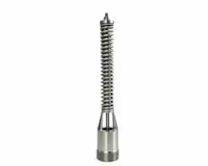
THINKTANK bellows sealed globe valves employ a multi-layer bellows seal structure, completely isolating the valve stem from high-temperature medium contact paths, eliminating leakage risks of traditional packing seals at high temperatures. Bellows materials use Inconel 625 or Hastelloy alloys, capable of withstanding temperatures above 600℃.

Problem 2: Medium crystallization causing seizure.
This is the number one killer of molten salt CSP systems. THINKTANK solution is body heating design: electric heating jackets or thermal oil circulation circuits are installed in the valve seat area, keeping the seat surface temperature always above the molten salt crystallization temperature. Even during system cooldown and shutdown, key valve areas remain warm, fundamentally preventing crystallized salt from seizing valves.
Problem 3: Thermal shock fatigue.
THINKTANK hard-sealed high-temperature ball valves employ a metal-to-metal hard seal plus elastic compensation element combination design. Metal sealing faces can withstand high temperatures without aging; elastic elements (such as springs or bellows) can absorb stress changes caused by thermal expansion/contraction, preventing seat deformation and seal failure.
Project Case: Northwest China 100MW CSP Plant
This power plant configures an 8-hour molten salt TES system, with Solar Salt (60% sodium nitrate plus 40% potassium nitrate) as the storage medium, operating at 290℃ to 565℃. THINKTANK provided a total of 86 bellows sealed globe valves and high-temperature hard-sealed ball valves for the molten salt circuit, covering key nodes such as cold salt pump outlets, hot salt pump inlets, and molten salt heater inlets/outlets. Since the system was commissioned in 2021, valve failure rate is zero, with no unplanned shutdowns caused by valve issues.
Scenario 3: Stratified Water Storage System
Stratified water storage is the mainstream technical approach for large data centers and district cooling systems. Its principle uses precise control of inlet flow velocity and direction to form a stable temperature stratification in the storage tank (warmer return water in the upper layer, colder supply water in the lower layer), thereby maximizing effective cold capacity storage[^3].
Recommended Product: Electric Proportional-Integral Control Valve (Three-Way/Two-Way)
The core challenge of stratified storage systems is: high-precision flow control at small openings. If the control valve precision is insufficient, colder water may mix with upper-layer warm water, causing temperature layer confusion in the storage tank and significant effective cold capacity attenuation.

THINKTANK electric proportional-integral control valves offer the following core advantages:
- Exceptional small opening precision: Control precision can reach within plus/minus 0.5%, ensuring stable temperature layer in the storage tank
- Excellent control characteristics: Equal percentage characteristic curve adapts to water system resistance, achieving smooth regulation across the full flow range
- Low leakage rate: Soft seal structure achieves less than or equal to 0.01% leakage rate in closed state, preventing cold capacity bypass losses
- Smart positioner integration: Supports 4-20mA analog signals or Profibus/Modbus digital communication, capable of integration with BMS building management systems for remote monitoring and automatic control
During selection, special attention should be paid to valve rangeability parameters. Ideal rangeability should exceed 50:1 to ensure good regulation characteristics under low-flow conditions. Additionally, valve shut-off pressure differential must match system pump capacity to prevent water hammer or cavitation.
Deep Analysis: Three Hidden Pitfalls
In practical TES engineering, there are three easily overlooked yet far-reaching issues. THINKTANK, combining extensive project experience, analyzes each in detail.
Pitfall 1: Flow Coefficient (Cv/Kv) Impact on PUE
Data center PUE is the core metric for measuring energy efficiency levels. Ideal PUE approaches 1.0 (all electricity used for IT equipment); actual large-scale data center PUE typically ranges from 1.1 to 1.4. Cooling system electricity consumption accounts for 30%-40% of total energy consumption, meaning every component resistance loss is amplified.
Valves, as local resistance components in piping systems, have their flow coefficient directly determining pump power consumption. The industry commonly uses CV value (imperial) or KV value (metric) to describe valve flow capacity. CV value is defined as: the number of gallons per minute flowing through the valve at 1 psi pressure drop. The larger the CV value, the smaller the valve resistance.
However, a common misconception exists in engineering practice: over-pursuing large CV values. When valve CV value far exceeds what the piping system requires, it can cause deteriorated regulation characteristics and unstable flow at small openings. The correct approach is through systematic hydraulic calculations to determine the minimum required CV value, then select the valve specification closest to that value.
THINKTANK recommendation: In data center TES system valve selection, require suppliers to provide complete CV value curves (actual flow coefficients at different openings) and conduct system-level pump power sensitivity analysis.
Pitfall 2: Thermal Stress-Induced Internal Leakage
TES system operating conditions require valves to withstand frequent temperature cycles. Taking CSP as an example, with daily charge-discharge cycles, valve metal seats undergo repeated thermal expansion and contraction, potentially causing the following failure modes:
- Seat surface microcracks, gradually developing into leakage channels
- Clearance changes between seat and body due to thermal expansion, causing insufficient sealing specific pressure
- Spring or elastic element failure due to thermal fatigue, losing compensation capability
THINKTANK solution is bimetal seal plus elastic compensation structure:
- Stellite alloy seat: Stellite cobalt-based hard alloy welding on seat sealing surface, providing wear resistance, corrosion resistance, and high-temperature resistance
- Disc spring compensation: Disc spring groups installed in seat support structure to compensate for thermal expansion-induced clearance changes
- Finite element thermal analysis: Customized thermal stress analysis for critical valves, ensuring reliability under extreme operating conditions
Pitfall 3: Intelligent Trend—From Valves to Smart Terminals
TES systems are moving toward a more intelligent operating model, shifting from passive execution to active perception. In traditional systems, valves mainly serve as actuation components. In the future, however, smart valves integrated with sensing, communication, and edge-level data processing capabilities are expected to play a much bigger role in TES system operation and maintenance.
At THINKTANK, this is one of the directions we are actively developing. Our target smart valve solution is planned around several key functions:
a. Integrated temperature and pressure sensing
Real-time monitoring of temperature and pressure conditions at critical valve points, with data transmitted to SCADA or BMS platforms
b. Predictive maintenance support
Using operating history and sensor data to help evaluate valve condition and support remaining-life assessment
c. Fault detection and alarm capability
Identifying abnormal signals such as unusual vibration, sealing degradation, or actuator timeout, and generating warnings
d. Remote tuning and parameter adjustment
Enabling engineers to optimize valve settings through digital communication interfaces without relying entirely on field intervention
Smart valves should not be understood as a simple hardware upgrade. More importantly, they represent a change in TES operation and maintenance philosophy. The long-term goal is to help TES systems move from reactive maintenance toward condition-based and data-driven management.
Conclusion: THINKTANK—More Than Just Valve Sales
Over the past decade, THINKTANK has deeply participated in dozens of TES project constructions domestically and internationally, accumulating rich experience across multiple scenarios including CSP, data centers, district cooling, and industrial waste heat recovery. We understand that TES system success depends not only on individual valve performance but more importantly on system-level fluid control strategies.
THINKTANK full lifecycle service system:
- Selection consultation: Free valve selection calculations and solution optimization based on your specific operating conditions
- Product customization: Support for special materials, special connection methods, and special actuation forms
- On-site services: Professional engineering team providing installation guidance, debugging support, and on-site training
- Spare parts reserve: Localized storage of critical valve spare parts, shortening maintenance response time
- Operation training: Regular user training classes to improve customer team operation capabilities
Engineering Selection Recommendations
- Data center emergency cold source scenario: Prioritize triple eccentric butterfly valves, focusing on response time (less than or equal to 50ms) and operating life (greater than or equal to 1 million cycles); require CV value curves and pump power sensitivity analysis
- CSP molten salt circuit: Must use bellows sealed valves, focusing on whether body heating function is equipped; seat material recommends Stellite alloy or Inconel 625; require supplier thermal shock test reports
- Stratified water storage system: Select electric proportional-integral control valves, focusing on small opening precision (within plus/minus 0.5%) and rangeability (greater than or equal to 50:1); confirm building system communication protocol support
- All TES projects: Recommend involving valve supplier technical participation in early project stages for system-level fluid calculation and optimization, avoiding later retrofit costs
The freezing and releasing of energy is the core proposition of modern energy systems. THINKTANK is committed to being the most trusted fluid control partner in this process—not just selling valves, but providing you with systematic guarantees for zero-loss energy transfer.
For further technical exchange or project consultation, please contact THINKTANK technical team.
FAQ (Frequently Asked Questions)
Q1: What is a TES Thermal Energy Storage System?
A1: A TES (Thermal Energy Storage) system is a system that stores heat or cold for use later. In simple terms, you produce thermal energy at one time, keep it in a storage medium, and release it later when the process or power system needs it.
Q2: Why are valves so important in TES systems?
A2: Valves are the traffic police of TES systems, determining thermal media flow direction, flow rate, and switching timing. Valve selection directly impacts system energy efficiency (up to 15% loss) and reliability.
Q3: How do valve requirements differ between high-temperature storage and low-temperature cold storage?
A3: High-temperature end requires ultra-400C resistance, bellows sealing, and thermal shock design; low-temperature end requires low pressure drop (energy saving), high-frequency operating life, and fail-safe capability.
Q4: What is the most common problem with molten salt circuit valves?
A4: The biggest issue is medium crystallization causing valve seizure. THINKTANK solution is body heating design, keeping valve seat temperature always above the crystallization temperature.
Q5: How to select valves for data center emergency cold source switching?
A5: Recommend globe type control valves or triple eccentric butterfly valves, response time less than or equal to 50ms, operating life greater than or equal to 1 million cycles, require CV value curves for pump power analysis.
Q6: How to select valves for CSP projects?
A6: Must use bellows sealed valves, seat recommends Stellite alloy or Inconel 625, require supplier thermal shock test reports and body heating function.
Q7: What are the key parameters for stratified water storage system control valves?
A7: Focus on small opening precision (within plus/minus 0.5%) and rangeability (greater than or equal to 50:1), confirm support for building system communication protocols (Modbus/Profibus).
Q8: What is the value of valve intelligence in TES systems?
A8: Smart valves enable built-in temperature/pressure sensing, predictive maintenance, fault self-diagnosis, and remote debugging, transforming O&M from fix after problems to intervene before problems.
Q9: Which typical applications are TES used for?
- CSP plants: store solar heat in molten salt so power can still be generated after sunset
- HVAC/building systems: make chilled water or ice at night and use it during the day
- Industrial plants: recover waste heat and reuse it later in the process
- District heating/cooling and some long-duration energy storage concepts
References
[^1]: IEA (International Energy Agency) – World Energy Outlook 2024
Link: https://www.iea.org/reports/world-energy-outlook-2024
Supports: Data center cooling systems account for 30%-40% of total energy consumption and PUE-related data
[^2]: U.S. Department of Energy (DOE) – Thermal Energy Storage Technologies Report
Link: https://www.energy.gov/eere/thermal-energy-storage-technologies
Supports: Technical difficulty descriptions of CSP molten salt TES systems and high-temperature operating conditions
[^3]: GB/T 51048-2025 – Technical Standard for Electrochemical Energy Storage System Thermal Management
Link: https://openstd.samr.gov.cn/
Supports: Stratified water storage temperature layer control and temperature difference requirements (within 3C)