This guide explains the basic automatic calibration and parameter setup procedure for an ABB fieldbus valve positioner.
Before commissioning, confirm that the valve, actuator, feedback linkage, air supply, and electrical connections are installed correctly.
Step by Step For ABB Fieldbus Valve Positioner Automatic Calibration
Step 1: Enter the Main Setup Menu
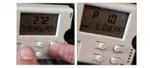
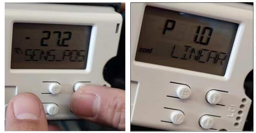
Press and hold the ↑ and ↓ arrow buttons, then press the E button.
Continue holding the ↑ and ↓ buttons for approximately three seconds until the positioner enters the setup menu.
Menu navigation:
- Press and hold M, then press ↑ or ↓ to switch between submenu items.
- Press and hold M and E together, then press ↑ or ↓ to switch between the main menu groups.
Step 2: Set the Action Direction and Start Calibration
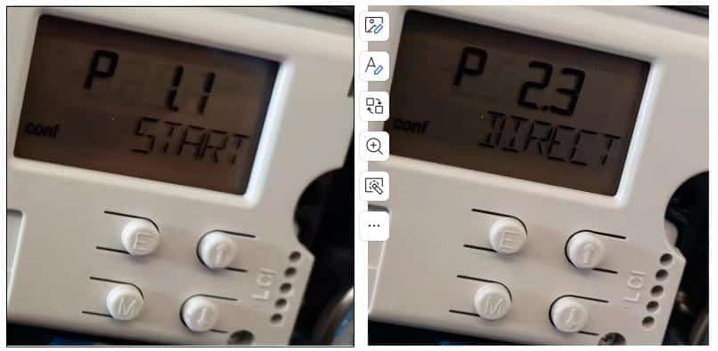
P1.1 — Automatic Calibration
Enter menu P1.1.
Press and hold the E button to start the automatic calibration procedure.
During calibration, the positioner will operate the valve automatically. Keep clear of all moving parts.
P2.3 — Direct or Reverse Action
Enter menu P2.3 to select the required operating direction:
- Direct action
- Reverse action
Confirm that the selected direction matches the valve and actuator fail action.
Step 3: Set the Lower and Upper Operating Limits
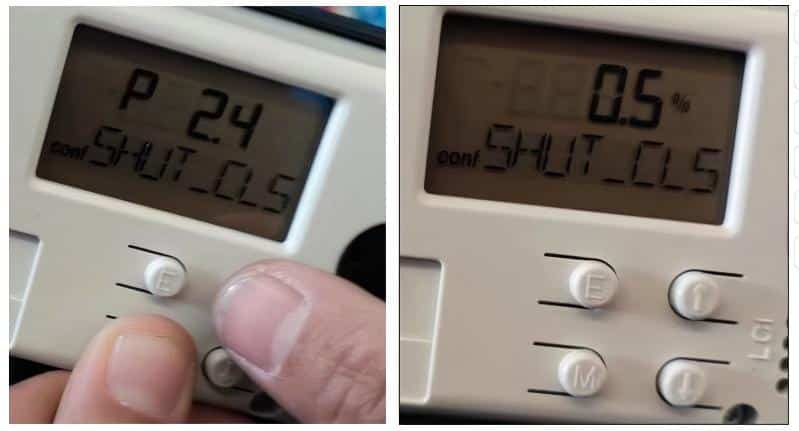
P2.4 — Initial Action Signal
Menu P2.4 sets the input signal at which the positioner begins to operate the valve.
The normal workshop setting is:
0.5%
P2.5 — Forced Full-Open Signal
Menu P2.5 sets the input signal at which the positioner forces the valve to the fully open position.
The normal workshop setting is:
99.5%
These settings help ensure that the valve reaches its required end positions.
Step 4: Configure the Input Signal and Deadband
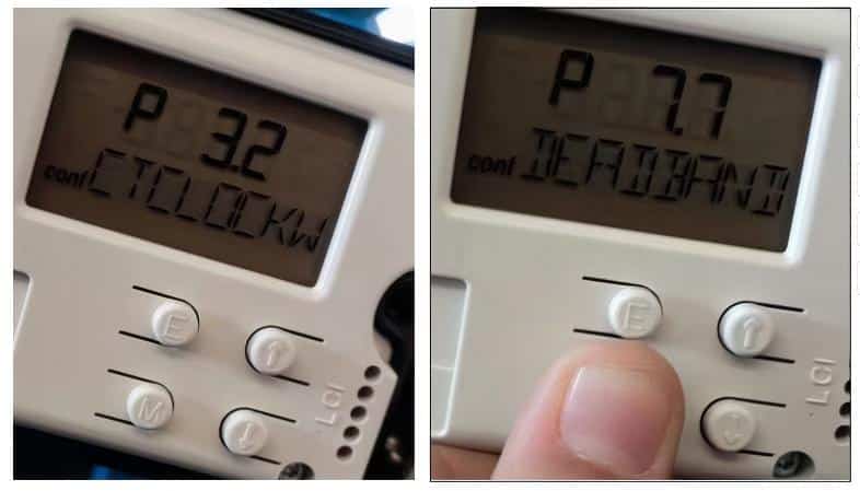
P3.2 — Input Signal Direction
Menu P3.2 is used to select the input signal direction:
- 4–20 mA
- 20–4 mA
Select the signal direction according to the control system requirements and the required valve action.
P7.7 — Deadband Setting
Menu P7.7 is used to adjust the positioner deadband.
Under normal operating conditions, this parameter should not be changed.
When the valve shows hunting, oscillation, or frequent small movements around the target position, the deadband may be increased appropriately.
Avoid setting the deadband excessively high, as this may reduce positioning accuracy.
Step 5: Configure the Feedback Signal or Restore Factory Settings
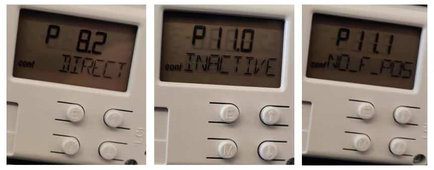
P8.2 — Feedback Signal
Menu P8.2 is used to configure the valve position feedback signal when the positioner is equipped with a feedback output function.
Modify this parameter only when the feedback signal direction or output configuration needs to be changed.
P11.0 and P11.1 — Factory Reset
Menus P11.0 and P11.1 are used to restore the positioner to its factory settings.
Complete and save both menu operations according to the positioner display prompts.
After restoring the factory settings, all required parameters must be checked and the automatic calibration must be performed again.
Step 6: Complete Calibration and Return to Operating Mode
After all required parameters have been configured, return to menu:
P1.1
Press and hold the E button to perform the automatic calibration.
Wait until the complete calibration process has finished.
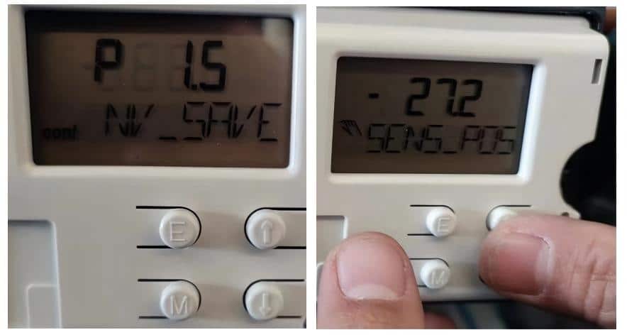
Then enter:
P1.5
Save the configured parameters and calibration results.
After returning to the menu, press and hold the M button and use the ↑ or ↓ arrow button to switch to:
P1.0
The positioner is now in normal operating mode and can be controlled using the input signal or fieldbus command.
Final Functional Check
After calibration, apply several control signals and verify the valve response.
Confirm that:
- The positioner is in P1.0 operating mode.
- The valve action direction is correct.
- The valve reaches the fully closed and fully open positions.
- The actual valve position follows the command signal.
- The feedback signal is correct, if fitted.
- The valve moves smoothly without hunting or abnormal oscillation.
- All modified parameters and calibration results have been saved.
Need Support with Control Valve Selection or Replacement?
THINKTANK is a professional control valve manufacturer with more than 30 years of industry experience.
In addition to valve positioner setup and troubleshooting support, our engineering team can help you select complete control valve assemblies based on the actual process conditions, including the valve body, trim, actuator, positioner, and accessories.
If you are looking for an alternative to an existing ABB, Fisher, Masoneilan, Flowserve, Samson, or other branded control valve, please send us the valve nameplate, datasheet, operating conditions, or current model number.
We can review the original valve specification and provide a technically compatible replacement solution with reliable performance, shorter delivery time, and a more competitive total cost.
Contact THINKTANK for control valve selection, troubleshooting, or replacement support.