This quick guide explains how to configure and automatically initialize a Siemens SIPART PS2 valve positioner using the local three-button interface. Before initialization, verify that the 2.YAGL setting matches the physical 33°/90° transmission ratio selector inside the positioner.
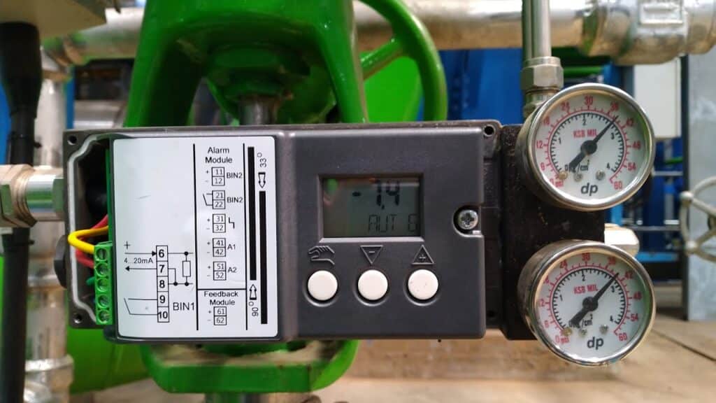
Button Functions
| Button | Function |
|---|---|
| Operating Mode Button | Select the operating mode, enter configuration and move to the next parameter |
| Decrement Button – | Decrease a value or move the actuator in manual mode |
| Increment Button + | Increase a value or move the actuator in manual mode |
To enter configuration mode, press and hold the Operating Mode button for at least five seconds. Pressing the Operating Mode button briefly moves to the next parameter. The + and – buttons change the selected parameter value.
Before Initialization
Make sure that:
- The positioner is correctly mounted.
- The feedback lever and carrier pin are correctly installed.
- The pneumatic tubing is connected correctly.
- Clean and sufficient instrument air is available.
- The electrical input signal is connected.
- The valve can safely move through its complete travel.
- The transmission ratio selector is set correctly.
Warning: Automatic initialization moves the valve through its full operating range. Isolate the valve from the process before starting.
Automatic Initialization Procedure
| Step | Procedure |
|---|---|
| 1. Check the Transmission Ratio Selector | Before switching on the positioner, confirm that the internal selector is set to 33° or 90° according to the actuator stroke. |
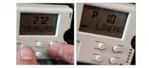
| 2. Position the Valve Near Mid-Travel | Use the + and – buttons in P-manual mode to move the valve near 50% travel. The displayed potentiometer value should preferably be between approximately P48.0 and P52.0. |
| 3. Enter Configuration Mode | Press and hold the Operating Mode button for at least five seconds. The display enters parameter configuration and shows 1.YFCT. |
| 4. Select the Actuator Type | Set parameter 1.YFCT according to the valve and actuator arrangement. |
| 5. Confirm the Feedback Angle | Open parameter 2.YAGL and confirm that the selected value matches the physical 33°/90° transmission ratio selector. |
| 6. Set the Linear Stroke Range | For a linear actuator, set parameter 3.YWAY according to the carrier-pin position shown on the feedback lever scale. |
| 7. Open Automatic Initialization | Move to parameter 4.INITA. |
| 8. Start Initialization | Press and hold the + button for at least five seconds until initialization starts. |
| 9. Wait for Completion | The positioner automatically runs through RUN1 to RUN5. Do not interrupt the air supply or electrical signal. |
| 10. Exit Configuration | When FINISH appears, press and hold the Operating Mode button for at least five seconds to exit configuration mode. |
| 11. Verify Operation | Apply several input signals and confirm that the valve moves in the correct direction and reaches both end positions. |
Siemens recommends starting initialization with the actuator near its mid-position. For units with a friction clutch, adjusting the displayed potentiometer value close to P50.0 improves stroke detection accuracy.
Step 1: Select the Actuator Type — 1.YFCT
The 1.YFCT parameter identifies the actuator and feedback arrangement.
| Setting | Application |
|---|---|
| WAY | Standard linear actuator with the carrier pin mounted on the feedback lever |
| -WAY | Linear actuator with inverted feedback direction |
| turn | Standard part-turn or rotary actuator |
| -turn | Part-turn actuator with inverted feedback direction |
| FWAY | Linear actuator with the carrier pin mounted directly on the actuator spindle |
| LWAY | Linear actuator using an external linear potentiometer |
For most globe control valves with a conventional feedback lever, select:
1.YFCT = WAY
For most ball valves and butterfly valves with direct rotary mounting, select:
1.YFCT = turn
Use the minus settings only when the mechanical feedback direction is inverted. For example, -turn is used when the valve closes as the positioner shaft rotates counterclockwise instead of clockwise.
Step 2: Set the Feedback Angle — 2.YAGL
After entering Configuration mode, briefly press the Operating Mode button to move to parameter 2.YAGL.
Select the feedback angle according to the actuator type and travel:
| Actuator and Travel | 2.YAGL Setting |
|---|---|
| Linear actuator, 5–20 mm travel with short lever | 33° |
| Linear actuator, 25–35 mm travel with short lever | 90° |
| Linear actuator, 40–130 mm travel with long lever | 90° |
| Rotary actuator | 90° |
Important: The
2.YAGLparameter must match the physical 33°/90° transmission ratio selector inside the positioner. A mismatch may cause incorrect position feedback or initialization failure.
Step 3: Set the Linear Stroke — 3.YWAY
The 3.YWAY parameter is used for linear actuators.
Read the value indicated by the carrier pin on the positioner lever scale and select the corresponding value.
Available settings commonly include:
5,10,15or20 mmwith the short lever and 33° setting25,30or35 mmwith the short lever and 90° setting40,50,60,70,90,110or130 mmwith the long lever and 90° setting
Select:
3.YWAY = OFF
when displaying the calculated actuator stroke in millimetres is not required.
3.YWAY is not simply an approximate valve stroke entry. It should correspond to the feedback pin position on the lever scale.
Step 4: Start Automatic Initialization — 4.INITA
- Press the Operating Mode button briefly until
4.INITAappears. - Confirm that the valve can move freely.
- Press and hold the
+button for at least five seconds. - Release the button after the initialization sequence starts.
- Wait until the display shows
FINISH.
Depending on the actuator size and travel time, initialization can take several minutes.
Initialization Sequence
| Display | Function |
|---|---|
| RUN1 | Determines the actuator and valve direction of action |
| RUN2 | Determines the valve travel and both mechanical end positions |
| RUN3 | Measures the opening and closing travel times and performs a leakage-related check |
| RUN4 | Determines the minimum controller increments |
| RUN5 | Optimizes the transient and control response |
| FINISH | Automatic initialization has been completed |
Some newer device configurations may include an additional RUN6 for diagnostic functions such as Valve Signature.
Setpoint Direction — 7.SDIR
The 7.SDIR parameter determines how the valve responds to an increasing input signal.
| Setting | Function |
|---|---|
| riSE | An increasing input signal moves the valve toward the open position |
| FALL | An increasing input signal moves the valve toward the closed position |
For a standard 4–20 mA control signal:
riSE
- 4 mA = valve closed
- 20 mA = valve open
FALL
- 4 mA = valve open
- 20 mA = valve closed
The factory setting is normally riSE. The correct selection depends on the project control logic and required valve action.
Display and Position Feedback Direction — 38.YDIR
The 38.YDIR parameter changes the direction of:
- The position value shown on the local display
- The analogue position feedback signal, when fitted
| Setting | Display Direction |
|---|---|
| riSE | Displayed position increases as the valve moves toward the defined open position |
| FALL | Displayed position decreases in the opposite direction |
Important:
38.YDIRdoes not reverse the actual input-signal control action. Use7.SDIRwhen the relationship between the input signal and valve movement must be reversed.
Manual and Automatic Modes
Manual Mode
After initialization, briefly press the Operating Mode button to switch from automatic mode to manual mode.
Use:
+to move the actuator in one direction–to move the actuator in the opposite direction+and–together to move more quickly toward an end position
In manual mode, the valve does not automatically follow the external setpoint.
Automatic Mode
Briefly press the Operating Mode button again to return to automatic mode.
In automatic mode, the positioner follows the incoming 4–20 mA or communication setpoint.
Canceling Initialization
Automatic initialization can be canceled by pressing the Operating Mode button.
After cancellation:
- The display returns to
INITA. - Press and hold the Operating Mode button for at least five seconds to leave configuration mode.
- Correct the mechanical, pneumatic or parameter problem.
- Restart initialization.
The settings determined before cancellation may remain stored unless the initialization parameters are reset through PRST.
Factory Reset
The parameter number for factory reset depends on the SIPART PS2 version:
| Device Version | Typical Parameter |
|---|---|
| Older SIPART PS2 | 55.PRST |
| Newer HART SIPART PS2 | 50.PRST |
| PROFIBUS PA version | May use a different number |
| Foundation Fieldbus version | May use a different number |
Always search for the parameter name:
PRST
rather than relying only on the parameter number.
Factory Reset Procedure
- Enter configuration mode.
- Move to the
PRSTparameter. - Select the required reset group.
- Press and hold the
+button. - Continue holding until the display shows
oCAY. - Release the button.
- Reconfigure and reinitialize the positioner.
Possible reset selections may include:
| Setting | Function |
|---|---|
| ALL | Resets initialization, application and diagnostic parameters |
| Init | Resets only the initialization parameters |
| PArA | Resets application parameters |
| diAg | Resets diagnostic parameters |
After selecting ALL or Init, a new valve initialization must be performed.
Common Initialization Problems
Initialization Stops at RUN1
Check:
- Instrument air pressure
- Pneumatic tubing
- Blocked restrictors
- Actuator freedom of movement
- Whether initialization was started from an end position
Initialization Stops at RUN2
Check:
- Whether
2.YAGLmatches the 33°/90° selector - Whether the feedback lever length is correct
- Whether the carrier pin is correctly positioned
- Whether the actuator can reach both end stops
- Whether the actual stroke is suitable for the selected lever
Initialization Does Not Reach FINISH
Check:
- Excessive valve friction
- Air leakage
- Insufficient supply pressure
- Incorrect mechanical mounting
- Excessively slow actuator movement
- Incorrect actuator or feedback settings
These are among the common causes identified in Siemens SIPART PS2 initialization troubleshooting instructions.
Final Function Check
After initialization, apply the following input signals:
| Input Signal | Expected Position with 7.SDIR = riSE |
|---|---|
| 4 mA | 0% |
| 8 mA | 25% |
| 12 mA | 50% |
| 16 mA | 75% |
| 20 mA | 100% |
Confirm that:
- The valve moves in the correct direction.
- The displayed position matches the actual valve position.
- The valve reaches both end positions.
- The movement is stable without continuous hunting.
- The positioner returns to automatic mode.
- No active fault message remains.
Quick Setup Sequence
For a standard linear control valve:
Check selector → P50 mid-position → 1.YFCT: WAY → 2.YAGL → 3.YWAY → 4.INITA → Hold + → FINISH
For a standard rotary valve:
Selector: 90° → Mid-position → 1.YFCT: turn → 2.YAGL: 90° → 4.INITA → Hold + → FINISH