Engineering Design, Material Science, and Global Application Overview
In the global energy transition and decarbonization process, Long-Duration Energy Storage (LDES) technologies are considered a core means of addressing the intermittency of renewable energy. Molten salt Thermal Energy Storage (TES) has become a standard configuration for Concentrating Solar Power (CSP) and next-generation nuclear power systems due to its high energy density, long lifespan, low cost, and superior safety compared to existing power battery systems. As the core carrier of this system, the design and construction of molten salt storage tanks involve complex structural mechanics, and are deeply coupled with high-temperature material science, electrochemical corrosion kinetics, and thermal fluid dynamics. This report provides a comprehensive analysis of molten salt storage tanks across dimensions such as thermophysical foundations, structural engineering design, material science challenges, global commercial applications, and future technological evolution.
Thermophysical Foundations and Operational Principles
The core logic of molten salt energy storage lies in utilizing the sensible heat storage characteristics of inorganic salts in their liquid state. Unlike Latent Heat Storage (PCM), sensible heat storage achieves energy absorption and release by changing the temperature of the medium, a method that is more mature and lower in cost for engineering implementation.1
Thermodynamic Quantitative Analysis of Storage Capacity
The total heat storage $Q$ of a molten salt system follows the law of conservation of energy, calculated as:

In practical engineering, the energy storage density of the system is jointly limited by the specific heat capacity Cp, density ρ, and the operational temperature difference △T. Taking the mainstream “Solar Salt” (binary nitrate) as an example, under a typical working window of 290℃ to 565℃, its volumetric heat capacity can reach approximately 200 kWh/m³ 2. This high energy density enables large-scale energy storage within a relatively small footprint.
Comparative Thermophysical Properties of Molten Salt Media
The choice of molten salt directly determines the design limits of the storage tank. Currently, the most widely used commercial salt is a mixture of 60% sodium nitrate NaNO3 and 40% potassium nitrate KNO3. Additionally, specialized salts for different temperature ranges are under research and demonstration.
| Trait | Binary Nitrate (Solar Salt) | Ternary Nitrate (with LiNO3) | Hitec Salt | Chloride Salts (Gen3 Target) |
| Melting Point ($^{\circ}C$) | ≈ 240 | ≈ 124 | ≈ 142 | ≈ 450-500 |
| Stability Limit ($^{\circ}C$) | ≈ 565-600 | ≈ 550 | ≈ 538 | ≈ 800+ |
| Viscosity (at $300^{\circ}C$, cP) | ≈ 4-7 | ≈ 7-8 | ≈ 3-4 | Low (at high temp) |
| Cost Level | Low | Extremely High (due to Li) | Medium | Medium |
| Main Application | Commercial CSP Tower/Trough | LDES Research | Trough CSP / Industrial Heat | Next-gen Supercritical Systems |
Research indicates that although lithium-bearing ternary salts have extremely low melting points, which can effectively reduce anti-freeze energy consumption, their specific heat capacity decreases from 1.794 J/g · K to 1.409 J/g · K over long-term operation (approximately 15,000+ hours). This is mainly due to the decomposition of LiNO_3 and the formation of precipitates from the reaction of lithium oxides with impurities.3
Structural Engineering and System Configurations
The design of molten salt tanks must overcome stress creep, thermal expansion/contraction, and heavy liquid column pressure in extreme high-temperature environments. Current engineering practices have evolved into several forms, including two-tank systems and single-tank thermocline systems.
Two-Tank Systems: Stability Analysis of the Commercial Benchmark
The dual-tank configuration is the only large-scale commercially verified technology, consisting of a “cold tank” (maintained at approximately 290℃ and a “hot tank” (usually at 565℃. The core advantage of this design lies in the “complete decoupling of power and capacity”: increasing storage duration only requires increasing the tank size and salt volume, without needing to increase the power of heat exchangers.4
During the charging cycle, cold salt is pumped from the cold tank, through a solar receiver or waste heat boiler to be heated, and then stored in the hot tank. The discharging cycle is the reverse, where hot salt passes through a steam generator to produce supercritical steam that drives a turbine for electricity. This system maintains a constant outlet temperature, which is highly valuable for grid dispatch and steam turbine longevity.5
Thermocline and Filler Storage: Paths to Cost Reduction
To reduce capital expenditure (CAPEX) by approximately 35%, the academic and engineering communities are working on single-tank systems. In a single tank, the natural stratification of the fluid is utilized (hot salt with lower density at the top, cold salt with higher density at the bottom), forming a thermocline transition layer several meters thick.6
- Solid Filler Technology: To further reduce costs, the tank can be filled with 50%-75% inexpensive solid media (such as pebbles or ceramic bricks), with molten salt acting only as the heat transfer fluid in the pores. The challenges of this design lie in the mechanical lateral pressure of the solid filler on the tank walls and maintaining thermocline stability during charge/discharge cycles.7
- Floating Barrier Design: Another innovative solution involves placing a floating disc or barrier with a density between that of hot and cold salt to physically reduce thermal convection and mixing.8
Tank Foundation Design and Thermal Management
Tank foundations must not only carry loads of tens of thousands of tons but also possess extreme thermal management capabilities to prevent soil drying/cracking or concrete failure. Modern large-scale molten salt tanks (with diameters up to 40 meters and salt volumes of 30,000 tons) typically use multi-layer composite foundations.9
| Foundation Layer | Common Materials | Core Function |
| Tank Bottom Contact | Alumina Silicate Fiber / Firebrick | Thermal insulation; reduces heat flow to concrete |
| Load-bearing Insulation | Foam Glass / Lightweight Concrete | Provides structural support while limiting heat loss |
| Cooling System | Active Ventilation / Water Cooling | Maintains concrete temperature within 60-80℃ |
| Structural Support | Pile-Raft Foundation | Reduces uneven settlement; enhances geological adaptation |
Studies show that using a pile-raft foundation can reduce the center settlement of the foundation’s top surface by 380.1 mm compared to traditional modes, significantly improving the safety of large tanks in complex geological conditions.
High-Temperature Material Science: Corrosion, Creep, and Life Prediction
At working temperatures of 565℃ and above, molten salts are not only highly oxidative, but their physical properties also pose severe challenges to the mechanical strength of materials.
Performance Characterization of Key Candidate Materials
Material selection requires a balance between high-temperature creep strength, corrosion resistance, and economy. For cold tanks (< 400℃), carbon steel (such as ASTM A516 Gr70) can meet a 30-year lifespan with appropriate corrosion allowance (approx. 0.078 mm/year). However, hot tanks must use high-performance stainless steels or nickel-based alloys.10
- AISI 347H Stainless Steel: Currently the primary material for hot tanks, featuring good high-temperature strength. However, it is sensitive to “Stress Relaxation Cracking” (SRC), which can easily lead to cracks in weld heat-affected zones.11
- AISI 316L and 321H: Common alternatives that, while slightly lower in strength than 347H, exhibit better ductility and corrosion stability in specific salt environments.
- Nickel-based Alloys (Inconel 625 / Hastelloy N): The only choices for chloride salt systems (> 700℃). While their performance is excellent, their cost (exceeding 20/kg) severely limits their application in large-scale storage tanks.12
Corrosion Kinetics and Micro-mechanism Analysis
Molten salt corrosion is a complex physicochemical process influenced by temperature gradients, oxygen content, and salt purity.
- Static Corrosion and Oxide Layer Growth: In static molten salt, steel surfaces form protective iron oxide (Fe2O3) or spinel-structured (Fe3O4) layers. However, long-term thermal cycling causes these layers to spall, exposing fresh metal surfaces and leading to continuous corrosion.
- Impact of Impurities: Chloride ion (Cl-) impurities are the primary culprits in accelerating corrosion, as they can penetrate oxide layers to cause pitting. Additionally, magnesium salt impurities can decompose upon heating to produce NO2 gas, which is environmentally hazardous and enhances salt corrosivity.
- Electrochemical Corrosion: Acting as an electrolyte, molten salt generates galvanic currents at the junction of different metals or in areas with temperature differences, leading to rapid localized loss of metal elements.
Auxiliary Systems and Key Component Engineering
A molten salt tank does not exist in isolation; its efficient operation depends on precise pumps, valves, and monitoring systems.
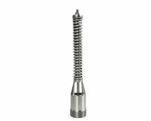
Design Constraints of Molten Salt Pumps
Vertical centrifugal pumps are the standard for molten salt tanks. Limited by the aspect ratio of the shaft and vibration control at high temperatures, the depth of molten salt tanks is typically restricted to 14 meters. This is because longer shafts are highly prone to thermal creep deformation and dynamic balance failure at 565℃. Furthermore, pump sealing systems must withstand salt spray and potential salt crystal wear.
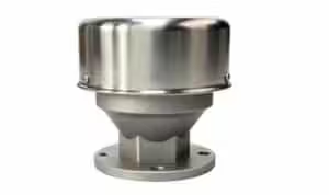
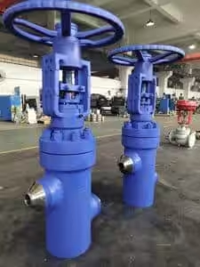
Technical Challenges of High-Temperature Molten Salt Valves
Achieving “zero leakage” at extreme temperatures is a major engineering challenge. Molten salt valves must address the following key issues:
- Anti-freeze Design: Valves are usually integrated with electric heat tracing systems to ensure the internal temperature remains above the salt’s solidification point (e.g., 240℃) to prevent the valve stem from “freezing”.
- Stuffing Box Sealing: Traditional graphite packing oxidizes above 500℃. Modern designs often use extended bonnets to move the seals away from the heat source and combine them with composite materials like PBI fibers.
- Thermal Stress Mitigation: Valve bodies must undergo Finite Element Analysis (FEA) to ensure that seat distortion does not occur during frequent thermal start-ups and shutdowns.
Commercial Project Lessons and Failure Analysis: The Case of Crescent Dunes
The Crescent Dunes project (110 MW) in Nevada, USA, as the world’s first large-scale commercial tower-type CSP plant with molten salt storage, has provided invaluable lessons for the industry.
Root Cause Analysis of Tank Floor Leaks
Since its commissioning in 2015, the project experienced four major hot salt tank leaks, leading to long-term shutdowns and eventual bankruptcy.
- Tank Floor Buckling: Due to the massive diameter of the hot tank and the large operational temperature difference, the steel floor plates generated enormous compressive stress when thermal expansion was restricted, eventually leading to upward buckling and deformation.
- Welding Residual Stress Interaction: Failure analysis by NREL pointed out that initial residual stresses generated during field welding were a “fingerprint” of the failure. During operation, these combined with thermal cycle stresses to exceed the yield strength of the 347H stainless steel, triggering fatigue cracks.
- Inadequate Mixing: If the inflow of hot salt does not mix adequately with the existing salt inventory, sharp temperature gradients can form at the tank floor. This non-uniform thermal load is a primary trigger for cracking.
As a countermeasure, the plant eventually had to reduce its operating temperature from the designed 565℃ to approximately 450−480℃, which resulted in a power output drop of about 45%, severely undermining the project’s economic viability.
Global Molten Salt Storage Landscape: The Rise of China
Globally, China has become the most active market for molten salt storage technology, with project scales and technological iteration speeds leading the world.
Overview of China’s CSP and LDES Market
By the end of 2025, China has built 27 CSP systems with a cumulative installed capacity of 1,738.2 MW, representing a 107% increase compared to 2024.
| Company / Project | Technology Route | Scale / Storage Duration | Status |
| Cosin Solar | Molten Salt Tower | 350 MW (Golmud) | World’s largest single unit, under construction |
| Shouhang High-Tech | Molten Salt Tower | 100 MW (Dunhuang) | In operation, broke multiple records |
| CHN Energy (Anhui Suzhou) | Coal + Molten Salt Storage | 1,000 MWh | Largest domestic coal plant flexibility project |
| CSSC New Energy | Molten Salt Trough | 100 MW (Urad Middle Banner) | Generated 301 million kWh in 2025 |
China’s leadership is reflected not only in capacity but also in innovative scenarios such as “Coal + Storage.” By adding molten salt storage tanks to existing coal-fired power plants, thermal-electric decoupling can be achieved, providing coal units with 100 MW-level deep-peaking capability and enabling the consumption of approximately 128 million kWh of wind and solar power annually.
Standardization Process: From API to ASME TES-1
Due to the limitations of traditional standards, the molten salt storage field is entering an era of dedicated codes. The release of ASME TES-1 (2020/2023) Safety Standard for Thermal Energy Storage Systems: Molten Salt marks the industry’s shift from empiricism to standard-driven design. This standard specifies requirements across the full lifecycle—from design, manufacturing, and installation to decommissioning—covering every technical aspect of tanks, pumps, valves, and heat exchangers. Chinese companies like Cosin Solar are also leading the preparation of multiple national standards for molten salt thermal storage, further solidifying the industry’s technical foundation.
Diversified Applications and Future Outlook
The application of molten salt storage tanks is expanding from CSP to nuclear energy, industrial heating, and hydrogen production.
Molten Salt Reactors (MSR): The Future of Nuclear Energy
In MSRs, molten salt acts not only as a coolant but often as the solvent for the nuclear fuel.
- Safety Advantages: MSRs operate at atmospheric pressure, eliminating the explosion risks associated with high-pressure light water reactors. The fuel salt naturally expands when overheated, creating a negative feedback effect that slows the reaction.
- Waste Management: Liquid fuel allows for online reprocessing, converting long-lived actinides into fuel and significantly reducing the half-life requirements for nuclear waste (from tens of thousands of years to approximately 300 years).
Industrial Process Heat and Hydrogen Integration
Molten salt tanks can serve as “thermal batteries,” providing stable high-temperature process heat for hard-to-abate heavy industries such as steel, ceramics, and chemical processing.
- Green Hydrogen: Utilizing the high-temperature heat stored in molten salts can drive High-Temperature Steam Electrolysis (SOEC) or thermochemical cycles for hydrogen production, with efficiencies much higher than low-temperature electrolysis.
- Waste Heat Recovery: Industrial waste heat can be stored in molten salt tanks and converted into electricity or industrial steam during peak demand periods, achieving efficient cascaded energy utilization.
Technological Evolution Trends
In the next decade, the development of molten salt storage tanks will focus on three major directions:
- Ultra-High Temperature (Gen3) Challenges: Chloride salt systems will push working temperatures above 700℃. This will completely transform tank design, shifting from “load-bearing metal” to “internal ceramic insulation + external metal support” structures.
- Digital Twins and Predictive Maintenance: Utilizing Fiber Bragg Grating (FBG) sensing and Digital Image Correlation (DIC) technologies to monitor tank strain in real-time, building physics-based models to identify fatigue cracks early.
- Novel Coatings and Surface Modification: Developing corrosion-resistant ceramic coatings or multi-layer composite liners on inexpensive steel surfaces holds the promise of maintaining a 30-year lifespan while significantly reducing material costs.
In conclusion, the molten salt storage tank is not only a mature engineering technology but also a continuously evolving frontier of scientific research. With breakthroughs in material science and the perfection of standardization, it will serve as an indispensable key link in building flexible, low-carbon power systems globally.
Reference
- Thermal energy storage – Wikipedi
- Molten Salt Storage for Power Generation
- Long-Term Evaluation of a Ternary Mixture of Molten Salts in Solar Thermal Storage Systems: Impact on Thermophysical Properties and Corrosion – PubMed
- Molten Salts Tanks Thermal Energy Storage: Aspects to Consider during Design – MDPI
- https://rpow.es/energy-storage-solutions/molten-salt-energy-storage/
- The thermal stability of molten nitrite/nitrates salt for solar thermal energy storage in different atmospheres | Request PDF – ResearchGate
- overview and specific insight into nitrate salts for sensible and latent heat storage – PMC – PubMed Central
- Thermal Energy Storage in Molten Salts: Overview of Novel Concepts and the DLR Test Facility (TESIS)
- Structure chart of the molten salt tank. | Download Scientific Diagram
- 565 °C Molten Salt Solar Energy Storage Design, Corrosion, and Insulation – David Publishing
- Failure Analysis for Molten Salt Thermal Energy Storage Tanks for In-Service CSP Plants
- Application Study of High-Temperature Corrosive Media Valves in the International Market
1. What is the most commonly used molten salt medium in commercial systems?
The industry standard for large-scale energy storage is Binary Nitrate Salt, often referred to as “Solar Salt”. It consists of a non-eutectic mixture of 60% sodium nitrate (NaNO3) and 40% potassium nitrate (KNO3). This mixture remains in a liquid state between a minimum operating temperature of 290℃ and a maximum of approximately 565℃. While advanced ternary salts (with LiNO3) offer lower melting points, binary nitrates remain preferred due to their optimized balance of cost, thermal stability, and heat capacity.
2. Why are molten salt tanks prone to leakage and structural failure?
Recent failures in high-temperature tanks are primarily attributed to several engineering factors:
Tank Floor Buckling: Significant temperature differences across large tank diameters cause restricted thermal expansion, leading to high compressive forces that cause the steel floor plates to buckle or warp.
Stress Relaxation Cracking (SRC): Materials like AISI 347H stainless steel, commonly used in hot tanks, are highly susceptible to SRC in weld heat-affected zones during thermal cycling.
Thermal Gradients: Insufficient mixing between incoming hot salt and the existing salt inventory can create severe localized temperature gradients, which significantly exceed the material’s yield strength.
3. How do engineers select materials for different tank types?
Material selection is strictly dictated by the operating temperature and the resulting corrosion rates:
Cold Tanks (< 400℃): Inexpensive carbon steel (e.g., ASTM A516 Gr70) is the standard, as corrosion rates at these temperatures are manageable.
Hot Tanks (approx 565℃): Austenitic stainless steels, specifically AISI 347H, 316L, or 321H, are required for their superior high-temperature creep strength and resistance to molten nitrate oxidation.
Gen3 Systems (> 700℃): Only high-nickel alloys (such as Inconel 625 or Hastelloy N) can withstand highly corrosive chloride salts at these temperatures, though their high cost (approx. $20/kg) remains a barrier.
4. What are the key industry standards for molten salt tank design?
Historically, tanks were designed using general petroleum or pressure vessel codes like API 650 or ASME Section II, which proved limited for extreme thermal cycling. To address this, ASME released the TES-1 standard (Safety Standard for Thermal Energy Storage Systems: Molten Salt), with the latest edition published in 2023. This dedicated standard provides comprehensive requirements for the entire life cycle of the equipment—including design, construction, testing, and decommissioning.
5. What applications exist for molten salt tanks beyond solar power?
Molten salt storage is increasingly being applied to diversify the energy landscape:
Thermal Repowering of Coal Plants: By integrating molten salt tanks into existing coal plants, utilities can decouple heat production from electricity generation. For instance, the CHN Energy Suzhou plant demo project provides 1,000 MWh of storage to enhance grid peak-shaving flexibility.
Molten Salt Reactors (MSRs): In next-generation nuclear energy, molten salts act as both coolants and fuel solvents. These systems operate at atmospheric pressure with passive safety features, such as “freeze plugs” that drain the salt to a containment vessel if overheating occurs.
Industrial Process Heat: These tanks serve as “thermal batteries” to provide high-grade heat (600℃) for hard-to-decarbonize sectors like steel production, chemical manufacturing, and hydrogen production via high-temperature electrolysis.