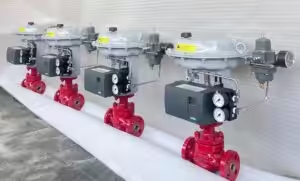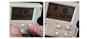
This quick guide explains how to configure and perform automatic stroke calibration on a Flowserve Logix 3200MD+ digital valve positioner using its local DIP switches and control buttons.
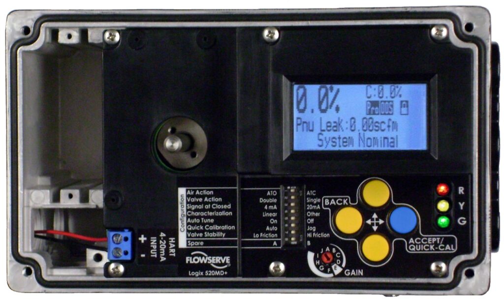
Button Functions
| Button | Function |
|---|---|
| ◄ BACK | Return to the previous menu or cancel an operation |
| ▲ UP | Move upward through the menu or increase a value |
| ▼ DOWN | Move downward through the menu or decrease a value |
| ► ACCEPT/QUICK-CAL | Confirm a selection or start stroke calibration |
The local interface also includes eight configuration switches, three status LEDs and a rotary GAIN selector.
Before Calibration
Make sure that:
- The positioner is correctly mounted on the actuator.
- The feedback linkage is correctly installed.
- Pneumatic tubing is connected correctly.
- Clean instrument air is available.
- The 4–20 mA input signal is connected.
- The valve can safely move through its full travel.
Warning: QUICK-CAL will move the valve to its fully closed and fully open positions. Isolate the valve from the process before starting calibration.
Step 1: Set the Configuration DIP Switches
| DIP Switch | Available Settings | Recommended Selection |
|---|---|---|
| Air Action | ATO / ATC | Select according to the pneumatic tubing and actuator movement. |
| Valve Action | Double / Single | Select Double for double-acting actuators or Single for single-acting actuators. |
| Signal at Closed | 4 mA / 20 mA | Select the input signal corresponding to the fully closed valve position. |
| Characterization | Linear / Other | Select Linear for standard commissioning unless another flow characteristic is specifically required. |
| Auto Tune | On / Off | Select On for automatic tuning during QUICK-CAL. |
| Quick Calibration | Auto / Jog | Select Auto when the valve has a mechanical stop at the fully open position. |
| Valve Stability | Lo Friction / Hi Friction | Use Lo Friction for most control valves. Use Hi Friction when additional stability is required. |
| Spare | Special function | Leave at the factory setting unless otherwise specified. |
The DIP-switch settings are applied when a stroke calibration is performed. Simply moving the switches without running QUICK-CAL does not activate the new configuration.
Air Action Setting
Select the air action according to the actual pneumatic connection:
- ATO — Air to Open: Increasing positioner output pressure causes the valve to open.
- ATC — Air to Close: Increasing positioner output pressure causes the valve to close.
Do not determine this setting only from the required fail-open or fail-close action. Check the actuator movement and pneumatic tubing first.
Signal at Closed
| Setting | Valve Response |
|---|---|
| 4 mA | Valve is closed at 4 mA and open at 20 mA. |
| 20 mA | Valve is closed at 20 mA and open at 4 mA. |
For most air-to-open control valves, 4 mA corresponds to the closed position. For many air-to-close applications, 20 mA corresponds to the closed position. The actual project control logic must always be confirmed.
Characterization Setting
Linear
Select Linear when valve travel should be directly proportional to the input signal.
For example:
- 4 mA = 0%
- 8 mA = 25%
- 12 mA = 50%
- 16 mA = 75%
- 20 mA = 100%
Other
Select Other when an equal-percentage, predefined or custom characterization curve is required.
The exact characterization curve must be selected or modified using a HART handheld communicator or Flowserve ValveSight DTM.
Step 2: Set the GAIN Selector
For normal initial commissioning, set:
Auto Tune = On
GAIN = E
Position E is the recommended starting point for most actuators.
| GAIN Setting | Response |
|---|---|
| B–D | More stable and slower response |
| E | Recommended default setting |
| F–J | Faster and more active response |
| A | Preserves manually configured custom gains |
GAIN should be selected according to the actual valve response, not only according to actuator size.
Step 3: Start Automatic Calibration
- Confirm that the Quick Calibration switch is set to Auto.
- Confirm that the valve has mechanical stops at both ends of travel.
- Press and hold ACCEPT/QUICK-CAL for approximately three seconds.
- Release the button when calibration begins.
- Allow the positioner to move the valve fully closed and fully open.
- Wait until the calibration is completed and the display returns to its normal status.
During QUICK-CAL, the positioner determines:
- Fully closed position
- Fully open position
- Valve stroke
- Stroke time
- Suitable control gains
After calibration, the positioner is ready for normal control. For a new installation, Flowserve recommends performing a second successful QUICK-CAL to optimize performance.
Calibration Completion
Calibration is complete when:
- The display returns to the normal operating screen.
- The LED status sequence begins with green.
- No active calibration error is displayed.
- The valve responds correctly to the command signal.
A green-first LED sequence indicates normal operation or a normal operating status.
Aborting QUICK-CAL
To stop calibration:
Briefly press the BACK button.
The previous calibration settings will be retained.
Jog Calibration
Select Jog when the fully open position does not have a mechanical stop and must be set manually.
Jog Calibration Procedure
- Set the Quick Calibration switch to Jog.
- Press and hold ACCEPT/QUICK-CAL for approximately three seconds.
- The positioner will close the valve and automatically register the 0% position.
- When the LEDs display G-R-R-R, use the UP and DOWN buttons to move the valve to approximately 100% open.
- Press ACCEPT/QUICK-CAL to confirm the fully open position.
- Wait for the calibration procedure to finish.
Jog calibration manually defines the span, but the closed position is automatically registered at the valve seat. An elevated zero requires a HART handheld communicator or ValveSight DTM.
Local Manual Valve Control
To move the valve manually from the local interface:
- Press and hold UP, DOWN and BACK simultaneously for approximately three seconds.
- Use UP and DOWN to move the valve.
- Briefly press ACCEPT/QUICK-CAL to exit local control.
During local manual control, the valve does not respond to external analog or digital commands.
Restore Analog 4–20 mA Control
When the positioner has accidentally been left in digital command mode:
- Hold the UP and DOWN buttons.
- Briefly press ACCEPT/QUICK-CAL.
- Release the buttons.
This resets the command source to analog 4–20 mA control.
This button combination does not switch the positioner into digital mode. Digital command control must be selected through HART communication or ValveSight.
Factory Reset
To restore factory defaults:
- Disconnect power from the positioner.
- Press and hold ACCEPT/QUICK-CAL.
- Restore power while continuing to hold the button.
- Release the button after the reset begins.
- Reconfigure the DIP switches.
- Perform a new QUICK-CAL.
A factory reset removes the previous calibration, tag information, valve data, alarm settings and user-configured limits. The positioner must therefore be reconfigured and recalibrated afterward.
Final Function Check
After calibration, apply the following command signals:
| Input Signal | Expected Valve Position* |
|---|---|
| 4 mA | 0% |
| 8 mA | 25% |
| 12 mA | 50% |
| 16 mA | 75% |
| 20 mA | 100% |
*This example applies when Signal at Closed = 4 mA and Characterization = Linear.
Confirm that:
- Valve movement follows the command signal.
- The valve moves in the correct direction.
- The valve reaches both end positions.
- There is no hunting or continuous oscillation.
- The display shows normal system status.
- No red alarm remains active.
Recommended Quick-Start Settings
For most standard control valves:
Air Action: According to actual tubing
Valve Action: Single or Double
Signal at Closed: 4 mA
Characterization: Linear
Auto Tune: On
Quick Calibration: Auto
Valve Stability: Lo Friction
GAIN: E