Control valves are indispensable in industrial automation, serving as the cornerstone for managing fluid flow and ensuring system integrity. As technology evolves, the selection and application of control valves have become more diverse, necessitating a thorough understanding of installation and commissioning practices. This guide, informed by industry insights and the expertise of THINKTANK, elaborates on critical considerations for control valve deployment, aiming to enhance operational reliability and efficiency.

Control Valve Installation Guidelines
As an engineer at THINKTANK, I’ve come to appreciate the nuanced complexities involved in the successful installation and operation of control valves within industrial systems. Before proceeding with the installation of any control valve, it’s crucial to verify that its size, pressure rating, materials, and end connections are precisely matched to the operating conditions it will face. This foundational step is pivotal to ensure the valve performs optimally and withstands the rigors of its environment.
At THINKTANK, we pride ourselves on providing our clients with detailed guidance on the correct installation procedures for our equipment. This includes comprehensive instructions on setup, routine maintenance, and regular upkeep. Recognizing the importance of support beyond the sale, we often offer on-site commissioning services and the option for a regular maintenance contract, ensuring our equipment continues to function flawlessly.
Ensuring that piping upstream and downstream of the control valve remains clear and unobstructed is essential. A valve’s performance can be significantly hampered by stresses from line distortion. It is, therefore, imperative to ensure all flanged joints are aligned accurately and that the pipework is sufficiently supported to mitigate these stresses.
In my experience, control valves exhibit optimal performance when installed in horizontal pipelines, with the spindles positioned vertically. This orientation is not arbitrary; it is designed to promote the longevity and reliability of the valve’s operation.
Prior to operational use, it’s common practice to subject pipework systems to pressure testing, often at pressures exceeding normal working conditions. This necessitates that both the control valve and its internal components are engineered to endure these elevated pressures without compromise.
It’s important to recognize that control valves are, at their core, precision instruments. Their functionality can be severely impaired by the ingress of dirt or other abrasive materials. To prevent such occurrences, the installation of pipeline strainers upstream of the control valve is essential in most applications, a practice we strongly advocate at THINKTANK.
Furthermore, ensuring valves are accessible for routine maintenance tasks—such as gland repacking or internal component replacement—is critical. Employing full bore isolating valves on either side of the control valve can significantly reduce plant downtime during maintenance activities.
For plants requiring uninterrupted operation, even during control valve maintenance, the installation of a high-quality valved bypass is often necessary. This bypass should ideally comprise a characterised throttling valve or an additional control valve with the correct Kvs value to prevent any operational leakage from impacting the control system. It’s my professional stance that manual bypasses should be avoided to maintain system integrity.
Correct installation also involves ensuring the medium flows through the valve in the designated direction, typically indicated by a ‘direction of flow’ arrow on the valve body. Adequate flow capacity and an acceptable pressure drop are also non-negotiable requirements for the valve’s successful integration into the system.
In steam lines, the inclusion of a steam separator and/or a trapping point upstream of the valve is critical. This setup prevents condensate carryover, which could otherwise diminish the valve’s service life. Additionally, a condensate drain is vital to prevent waterhammer and potential damage upon valve activation, ensuring the system’s safe and efficient operation.
At THINKTANK, our commitment to engineering excellence is reflected in our meticulous approach to control valve installation and maintenance. By adhering to these best practices, we empower our clients to achieve unparalleled operational efficiency and reliability in their industrial processes.
Actuators/Sensors Guidance
Following the manufacturer’s guidelines is crucial when installing actuators and sensors. Typically, actuators are installed vertically above the control valve. However, unique configurations might be necessary for electric actuators coupled with valves managing high-temperature mediums, like steam.
It’s important to position actuators away from adverse conditions including excessive heat, high humidity, or corrosive environments to prevent premature component failure, notably in diaphragms or electronic parts. Manufacturers will provide the maximum ambient temperature their devices can withstand. For electric actuators at risk of internal condensation, models equipped with built-in heaters are advisable. In environments where harsh conditions are unavoidable, selecting actuators designed to withstand these specific challenges is essential.
Actuator and sensor enclosures are typically rated according to national electrical standards, indicating their resistance to dust and water ingress. Utilizing electric actuators with inadequate enclosure ratings in environments prone to water exposure, such as hose-down areas, is ineffective.
When installing sensors, ensure they are fully immersed to accurately perform their sensing tasks. Employing pockets allows for easy inspection or replacement without draining the system but may slow response times. Using heat-conducting paste in these pockets can help reduce response delays.
Power and Signal Lines
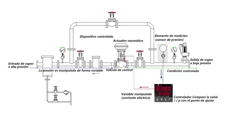
In pneumatic systems, it’s vital that compressed air and signal lines are dry, clean, and leak-free. Placing the pneumatic controller close to the valve and actuator reduces signal delay caused by line capacity and resistance.
Valves, actuators, and any associated positioners or converters are generally provided as a pre-assembled unit. If assembly is required, follow the manufacturer’s instructions carefully to ensure correct valve stroke and setup.
Electrical Wiring for Controls
Improper wiring is a common source of ‘control’ issues, such as connecting a 24 V motor to a 110 V supply, which can cause damage. Adhering to the manufacturer’s wiring instructions and local regulations is paramount.
Electrical ‘noise’ or interference can lead to operational challenges. Employing screened cables, separately earthed conduits, or using controllers designed to minimize interference can mitigate these issues. Additionally, cables should be safeguarded against mechanical damage.
Controllers
Typically, the application’s changes occur slower than the control system’s response time. This discrepancy necessitates tuning the controller’s parameters—proportional band or gain, integral time, and derivative time—to match the specific application.
Adjusting controller settings often involves mathematical calculations. Predicting control loop behavior is possible mathematically, but empirical measurements usually determine process characteristics, which can be complex. While design heat transfer ratios offer a method for adjustment, these techniques fall beyond this discussion’s scope.
Before tuning control parameters, understanding the implications of the control terms (P, I, and D) and the effects of various settings—too wide, too narrow, or correct—is beneficial for achieving optimal control performance.
Optimizing Proportional Bandwidth (P-band) Settings
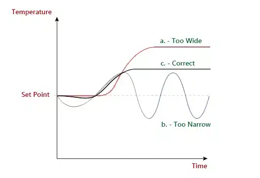
When configuring the Proportional (P) band in a control system, it’s essential to strike a delicate balance to ensure system stability and minimize offset. Referencing Figure 1 for visual guidance:
Wide P-band Settings
Employing a wider P-band can lead to significant offset, where the system’s response to changes is sluggish, resulting in a stable yet under-responsive operation (illustrated by curve a.). This setting, while making the system very stable, doesn’t provide the precision needed for most applications.
Narrowing the P-band
By reducing the P-band width, you can effectively decrease the offset, bringing the system’s output closer to the desired setpoint. This adjustment enhances control precision but must be approached with caution.
Excessively Narrow P-band
An overly narrow P-band setting introduces a high risk of instability and oscillation within the system (depicted by curve b.). This scenario is characterized by rapid fluctuations around the setpoint, which can lead to operational inefficiency and potential system wear.
Optimal P-band Setting
The ideal P-band setting, represented by curve c., is found just marginally wider than the threshold that induces permanent oscillations. This fine-tuning ensures the system maintains a balance between stability and responsiveness, optimizing performance without sacrificing control.
Achieving the optimum P-band requires careful observation and adjustment, tailoring the control system to respond efficiently to process variables while maintaining a stable operational state. This nuanced approach allows for precise control, ensuring the system operates effectively within its desired parameters.
| P-band Setting | Stability and Response | Offset |
|---|---|---|
| Optimal P-band | Good stability, good response | Some offset, manageable |
| Larger P-band | Better stability, slower response | Larger offset, less precise |
| Smaller P-band | Instability, quicker response | Smaller offset with oscillation |
Understanding Integral Action: Fine-tuning for Precision (Referencing Figure 2)
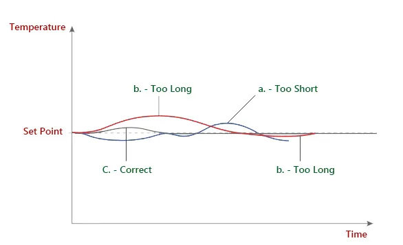
Short Integral Time
Behavior: When the integral time is set too short, the system’s temperature, as depicted by curve a, overshoots the desired setpoint. This premature reaction introduces oscillations, leading to instability within the control process.
Excessive Integral Time
Behavior: Setting the integral time too long causes a delayed response in temperature adjustment, as illustrated by curve b. This sluggishness prolongs the system’s return to the setpoint, compromising efficiency and control accuracy.
Optimal Integral Time
Behavior: The ideal integral time setting is showcased by curve c, where the system’s temperature correction is swift and precise, reaching the setpoint without any overshoot or oscillations. This setting exemplifies a well-calibrated control system, achieving rapid stabilization with impeccable accuracy.
This analysis underscores the importance of carefully adjusting the integral time to harmonize the system’s response with the setpoint, ensuring efficient and precise control without compromising stability.
| IAT Setting | Offset Elimination | System Response | Stability & Overshoot |
|---|---|---|---|
| Correct IAT | Yes | Balanced | Stable, no overshoot |
| Too Short IAT | Yes | Rapid, aggressive | Unstable, prone to overshoot |
| Too Long IAT | Yes | Delayed, sluggish | Stable, no overshoot |
Correct Integral Action Time IAT
A properly adjusted IAT effectively eliminates offset, ensuring a balanced response. The system remains stable with no overshoot, achieving optimal performance.
Too Short Integral Action Time IAT
While a shorter IAT also eliminates offset, it causes the system to respond too quickly. This can lead to instability, characterized by significant overshoot and potential control challenges.
Too Long Integral Action Time IAT
A longer IAT setting still manages to eliminate offset but results in a slower response from the system. Despite the sluggish reaction, this setting maintains stability without causing overshoot, making it suitable for processes where slower adjustments are preferable.
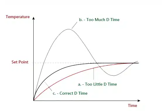
Optimizing Derivative Action for Temperature Control
The table below details the impact of derivative time adjustments on temperature control, as illustrated in Figure 3:
| Derivative Time Setting | Temperature Response | Stability Outcome | Illustration |
|---|---|---|---|
| Excessive | Rapid change, prone to overshoot | Oscillation | Curve b |
| Too Short | Slow to correct deviations | Deviates from set point | Curve a |
| Optimal | Quick correction to set point | Achieves good stability | Curve c |
Excessive Derivative Time
Setting the derivative time too high can lead to abrupt temperature changes, causing overshoot and subsequent oscillations in the system’s response (represented by curve b). This reactive setting can destabilize the process, making it challenging to maintain consistent control.
Too Short Derivative Time
Conversely, an overly short derivative time results in a sluggish reaction to deviations from the desired temperature set point (shown in curve a). This delay allows the temperature to stray from its target for an extended period, impacting the system’s efficiency and control accuracy.
Optimal Derivative Time
The ideal derivative time setting ensures that the temperature returns to the set point swiftly and maintains excellent stability across the system (depicted by curve c). This balanced approach minimizes overshoot and prevents oscillations, facilitating precise and reliable temperature control.
Commissioning: Optimal Controller Settings for Optimal Performance
Setting Up Controllers Practically
Customizing each controller to align with the unique dynamics of a specific system is paramount. Among various methods to achieve stable and efficient control, the Ziegler-Nicholls technique stands out for its efficacy.
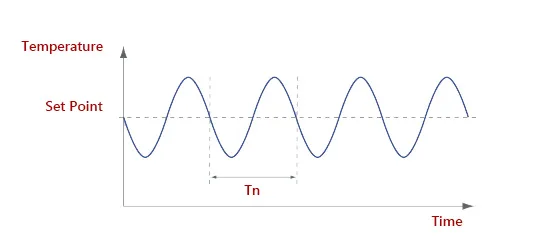
The Ziegler-Nicholls Method Explained
This method, also known as the critical oscillation method, is a robust strategy for fine-tuning controller settings to match the actual load. It involves using the controller as an amplifier to approach a point of instability, where the system exhibits constant amplitude fluctuations around the set point (refer to Figure 4). A slight increase in gain or a decrease in the proportional band can push the system into instability, causing the control valve to oscillate with growing amplitude. In contrast, expanding the proportional band enhances stability, gradually reducing oscillation amplitude. This process reveals the system’s characteristics under real operating conditions, capturing the dynamics of the heat exchanger, control valve, actuator, piping, and temperature sensor.
Ziegler-Nicholls Tuning Procedure
- Disable Integral Action: Increase the integral time (Ti) to its maximum to remove integral action from the controller.
- Disable Derivative Action: Set the derivative time (TD) to zero to eliminate the controller’s derivative action.
- Stabilize the Process: Wait for the process to stabilize.
- Identify Instability Point: Gradually reduce the proportional band (increase gain) until reaching the instability point.
- Measure and Register: Note the time period (Tn) of the temperature cycles and the proportional band setting at instability.
- Calculate Settings: Use these measurements as a basis to calculate optimal controller settings, as outlined in Figure 5.
| Control Strategy | Proportional Band Adjustment | Integral Time Setting | Derivative Time Setting |
|---|---|---|---|
| PID Control | P-band x 1.7 | Tn divided by 2 (Tn/2) | Tn divided by 8 (Tn/8) |
| PI Control | P-band x 2.2 | Tn divided by 1.2 (Tn/1.2) | Not applicable |
| P Control | P-band x 2.0 | Not applicable | Not applicable |
This table presents refined guidelines for setting Proportional (P), Integral (I), and Derivative (D) control parameters based on the Ziegler-Nicholls tuning method. These recommendations aim to optimize the performance of PID controllers by adjusting the Proportional band (P-band), Integral time (Ti), and Derivative time (Td) to suit different control strategies.
Key Terms:
- P-band: Proportional band setting, influencing the controller’s response to the error magnitude.
- Tn: Represents the natural period of the system’s oscillation, used as a baseline to determine I and D settings.
- Integral Time (Ti): Adjusts how quickly the controller responds to accumulated errors over time, aiming for zero steady-state error.
- Derivative Time (Td): Determines the controller’s response rate to changes in error, providing predictive action to mitigate overshoot and oscillation.
Adjustments to the controller settings may be further refined to enhance stability or response, with the effects illustrated in Figure 6.
| Adjustment | Effect on Stability | Effect on Response Time |
|---|---|---|
| Increase P Band | Enhanced Stability | Delayed Response |
| Increase Ti | Enhanced Stability | Delayed Response |
| Increase TD | Reduced Stability | Quicker Response |
Above table outlines the effects of adjusting Proportional (P) Band, Integral Time (Ti), and Derivative Time (TD) on system stability and response dynamics:
- Increasing Proportional Band (P Band): Elevating the P Band enhances the system’s overall stability, making it less prone to oscillations. However, this adjustment typically results in a slower response to changes, as the control action becomes more conservative.
- Increasing Integral Time (Ti): A higher Integral Time also contributes to improved system stability by gradually correcting offset errors over time. Like an increased P Band, this leads to a slower response as the system takes more time to adjust to setpoint deviations.
- Increasing Derivative Time (TD): Contrary to increasing P Band and Ti, boosting the Derivative Time decreases stability by making the system more sensitive to rate changes. This sensitivity can lead to faster responses to process disturbances but may also introduce a risk of overshooting and increased oscillation if not properly tuned.
Bumpless Transfer
A key feature in modern controllers is ‘bumpless transfer,’ allowing seamless switching between manual and automatic control without losing set levels. This functionality ensures matching outputs during transitions, facilitating smooth operation.
Self-tuning Controllers
Advancements in microprocessor technology have led to controllers capable of self-tuning. These devices temporarily switch to on/off control, analyzing response outcomes to autonomously calculate and set PID terms. Originally limited to initial setup, modern controllers now boast adaptive functions. They not only establish initial PID settings but also adjust them in response to ongoing process changes, ensuring sustained optimal performance. These self-tuning controllers are increasingly accessible and cost-effective, broadening their application across various control tasks.
Conclusion
The installation and commissioning of control valves are intricate processes that demand meticulous attention to detail. By adhering to best practices in inspection, testing, calibration, and installation, industrial facilities can significantly enhance the reliability and efficiency of their operations. THINKTANK’s expertise in control valve technology underscores the importance of precision and quality in every step of these processes, ensuring that industrial systems achieve optimal performance with minimal downtime. Through collaboration and adherence to stringent quality standards, the successful deployment of control valves can be achieved, contributing to the overall success and productivity of industrial projects.