Please enter the relevant terms or keywords you need to consult, and relevant articles will appear in the search results. If you can’t find the answer you need, please feel free to contact us and we will be happy to help. Or you can directly send an email to [email protected]
How Anti-Surge Valves Work: Pneumatic Control Logic, Failure Modes, and Engineering Design Considerations
Anti-surge valves are not just fast recycle valves. In real compressor service, they often have to modulate during normal operation and move quickly during upset conditions. This article explains how a typical pneumatic anti-surge valve package works, where field problems usually start, and what engineers should confirm before FAT or final approval.
Quick Take
Anti-surge valves are difficult because they must do two jobs at once: modulate during normal operation and move fast during upset conditions. In practice, many field problems do not come from the valve body alone, but from actuator sizing, pneumatic logic, accessory matching, and fail-action definition. This article explains what engineers should really check before approving an anti-surge valve package.
What This Article Covers
In this article, we cover:
why anti-surge duty is different from normal control valve duty
why high-performance butterfly valves and single-acting actuators are common
how the pneumatic control chain affects real valve behavior
why packages that look correct on paper still fail in the field
the most common anti-surge valve failure modes
what engineers should confirm before FAT or final approval
1. Anti-Surge Duty Is Not Just a Valve Sizing Problem
One of the most common mistakes in anti-surge projects is to treat the valve as a normal control valve with a fast opening requirement added on top. That usually leads to an incomplete review.
An anti-surge valve is part of compressor protection. That changes the design logic from the start.
A normal modulating control valve is mostly judged on controllability, rangeability, shutoff class, and long-term stability. A trip valve is mostly judged on its ability to move to the required end position under a defined failure condition. An anti-surge valve usually sits between those two worlds. It has to regulate during normal operation, but it also has to behave predictably and quickly when the protection system needs it.
That is why engineers cannot review anti-surge duty by asking only one question such as “Is Cv enough?” or “Can the valve open in two seconds?” Those are important questions, but they are not enough by themselves.
A valve may have sufficient Cv and still not perform well in anti-surge service. A fast stroke in shop testing does not guarantee the same response in the field. Even when fail action is correctly defined on the datasheet, the real protection logic can fail if the pneumatic switching chain is not properly reviewed.
Flow capacity is only one part of the review. In real projects, fail action, actuator margin, pneumatic switching logic, accessory quality, and field conditions often decide whether the package performs well or causes trouble later.
2. Why High-Performance Butterfly Valves Are Common in Anti-Surge Service
For many large recycle lines, high-performance butterfly valves are a practical choice. The reasons are familiar to most engineers.
First, they can provide high flow capacity in larger sizes without becoming excessively heavy or complex. In anti-surge duty, recycle capacity is not a secondary issue. If the valve opens but cannot pass enough flow, the compressor is not truly protected.
Second, quarter-turn movement makes it easier to build a fast package. That does not mean every butterfly valve is automatically suitable for anti-surge duty, but it does mean the architecture is often favorable when fast movement is required.
Third, high-performance butterfly valves are frequently paired with pneumatic actuators in a way that makes defined fail action more straightforward.
That said, it is important not to oversimplify the decision. A valve type is not suitable for anti-surge service just because it is a butterfly valve. What matters is whether the whole package fits the duty: valve body, actuator, accessories, pneumatic layout, control logic, and expected field conditions.
In practice, engineers should not ask only, “Why use a butterfly valve?” A better question is, “Why does this complete butterfly valve package make sense for this compressor protection duty?”
3. Why Single-Acting Pneumatic Actuators Are So Common
Many anti-surge valves use single-acting pneumatic actuators.
In protective service, engineers want predictable behavior during abnormal conditions. If air supply is lost, if power is lost, or if the circuit must switch into a protective state, the valve must move in the direction required by the compressor protection philosophy. A spring-return actuator makes that easier to define and easier to verify.
This is why phrases such as “fail open” are so common in anti-surge discussions. But it is worth being careful here. “Fail open” is not a universal truth. It is only correct when that action matches the actual protection logic of the system.
Engineers should not ask only whether anti-surge valves should fail open; they should ask what fail action is required to protect this compressor under the defined process philosophy.
In some projects, teams agree on the valve type and actuator style early, but the actual fail logic is not fully aligned between the compressor supplier, control team, packager, EPC, and valve vendor. When that happens, problems usually appear late, often during interlock review or functional testing.
From THINKTANK’s point of view, fail action should never be reviewed as a label only. It should be checked as a complete action chain:
what happens when power is lost
what happens when instrument air is lost
what happens when the solenoid changes state
what happens when ESD logic is activated
whether the actuator, switching logic, and valve movement all remain consistent with the compressor protection requirement
If that chain is not reviewed as a whole, the package is not really reviewed.
Fail action must be reviewed as a movement chain, not just a datasheet label: confirm how the solenoid changes state, how the actuator responds, and whether valve movement matches the compressor protection philosophy.
4. The Pneumatic Logic Often Decides Whether the Package Will Work Well or Not
Many engineers naturally begin with the valve body. That is understandable. But in anti-surge service, the pneumatic circuit often has just as much influence on performance as the valve itself.
A typical anti-surge package may include a filter regulator, solenoid valve, positioner, booster or quick exhaust device, limit switches, continuous position feedback, and various tubing connections and fittings. On paper, that may look like a routine accessory list. In practice, those items determine whether the package responds cleanly, tracks the control signal properly, and behaves correctly under protective action.
The filter regulator is more important than it looks. If the instrument air is unstable, dirty, wet, or oily, the rest of the package starts from a weak foundation. Slow response, sticky motion, drifting performance, and inconsistent repeatability often begin here.
The solenoid valve is another critical point. In many anti-surge packages, it is one of the main devices that defines the change between normal modulation and protective action. If the solenoid shifts slowly, sticks, or is poorly matched to the circuit, the entire fail-action philosophy becomes less reliable than it appears in the documentation.
The positioner matters because anti-surge valves are not usually idle devices waiting only for emergency action. They often need to modulate during normal operation. If the positioner setup is poor, the valve may move, but it may not track well, may drift at smaller openings, or may respond inconsistently under changing conditions.
Boosters and quick exhaust devices are often added when stroke-time targets are tight. These accessories can make a major difference, but they must be reviewed as part of the whole package. A booster is not a magic fix. It can improve speed, but if the actuator is undersized, if tubing is restrictive, or if the pneumatic logic is poorly arranged, the result may still be disappointing.
Table 1 — Where Many Anti-Surge Problems Actually Start
Component
Main Function
Common Problem in the Field
Filter regulator
Stabilizes and cleans instrument air
Dirty or unstable air causes slow, sticky, or inconsistent movement
Solenoid valve
Switches between normal control and protective action
Sticking, incorrect voltage, or weak switching can break fail action
Positioner
Controls valve movement during modulation
Poor setup can cause tracking error, drift, or unstable response
Booster / quick exhaust
Improves response speed
Helps speed, but cannot fix weak actuator sizing or poor circuit design
Continuous position feedback
Shows true valve position across the range
End switches alone do not show real modulating behavior
Tubing and fittings
Connect the pneumatic action chain
Small tubing, long runs, or restrictive layout can slow the whole package
Continuous valve position feedback is also frequently undervalued. In anti-surge service, knowing whether the valve once reached fully open or fully closed is not enough. Engineers usually need to know how the valve behaves across the operating range. That is why continuous position feedback is much more useful than simple open-close indication when evaluating actual anti-surge performance.
5. Why Packages That Look Correct on Paper Still Fail in the Field
This is one of the most important points in anti-surge engineering.
A package can look acceptable in the datasheet, pass a basic bench test, and still perform badly after installation. That happens more often than many teams expect.
One common reason is that stroke time is stated without realistic boundary conditions. A number such as “< 2 seconds” looks impressive, but it means very little unless engineers also know the air supply pressure, the actuator size, the tubing arrangement, the accessory setup, the starting valve position, and the actual load assumptions. A shop number without context is not the same as field performance.
Another common reason is that fail action is approved in wording but not in action logic. It is not enough to write “fail open” in a datasheet. Engineers must confirm how the solenoid changes state, how the actuator responds, and whether the entire pneumatic path actually delivers that movement under the failure mode that matters.
A third problem is that the accessory package is treated as routine rather than performance-critical. In normal valve procurement this sometimes works. In anti-surge duty, it usually does not. The difference between a stable package and an unreliable one often comes from the accessory choices, tubing layout, and actuator margin rather than from the valve body alone.
A fourth issue is that vibration, site conditions, and maintenance access are not reviewed seriously enough. A package may perform well in a controlled shop environment but behave very differently once mounted on a real line with vibration, limited access, less stable air conditions, and long-term operating wear.
This is why, in practice, anti-surge service should be reviewed as a package behavior problem, not only as a component selection problem.
A package can pass a basic shop test and still perform badly after installation. Stroke time, fail action, and control stability often change when real tubing layout, vibration, air quality, accessory restriction, and field wear are added to the picture.
In practice, many of these issues are not caused by the valve itself, but by how the test conditions differ from real operating conditions.
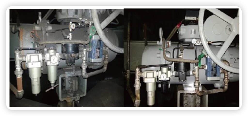
6. Case Study: Opening Delay in an Anti-Surge Valve Package
Project Background
In a compressor recycle system, a pneumatic spring-return anti-surge valve was installed to provide both modulation and surge protection.
The valve was designed to open quickly during surge events while maintaining stable control during normal operation.
However, during testing and early operation, the valve response did not meet expectations.
Problem Observed
The main issue was opening delay during surge-related action.
The valve did not move as quickly as required when the protection signal was triggered. A noticeable lag was observed between the command signal and the actual valve movement.
Under normal modulation, the valve could still operate, but the dynamic response was not reliable enough for anti-surge protection.
Root Cause Analysis
The problem was not related to the valve body itself, but to the pneumatic action chain.
Field review identified three practical causes:
switching delay at the solenoid valve
restrictive air path due to tubing layout and accessory arrangement
insufficient dynamic response margin in the overall pneumatic circuit
As a result, although the fail-open philosophy was correct, the actual opening speed in service did not fully match the protection requirement.
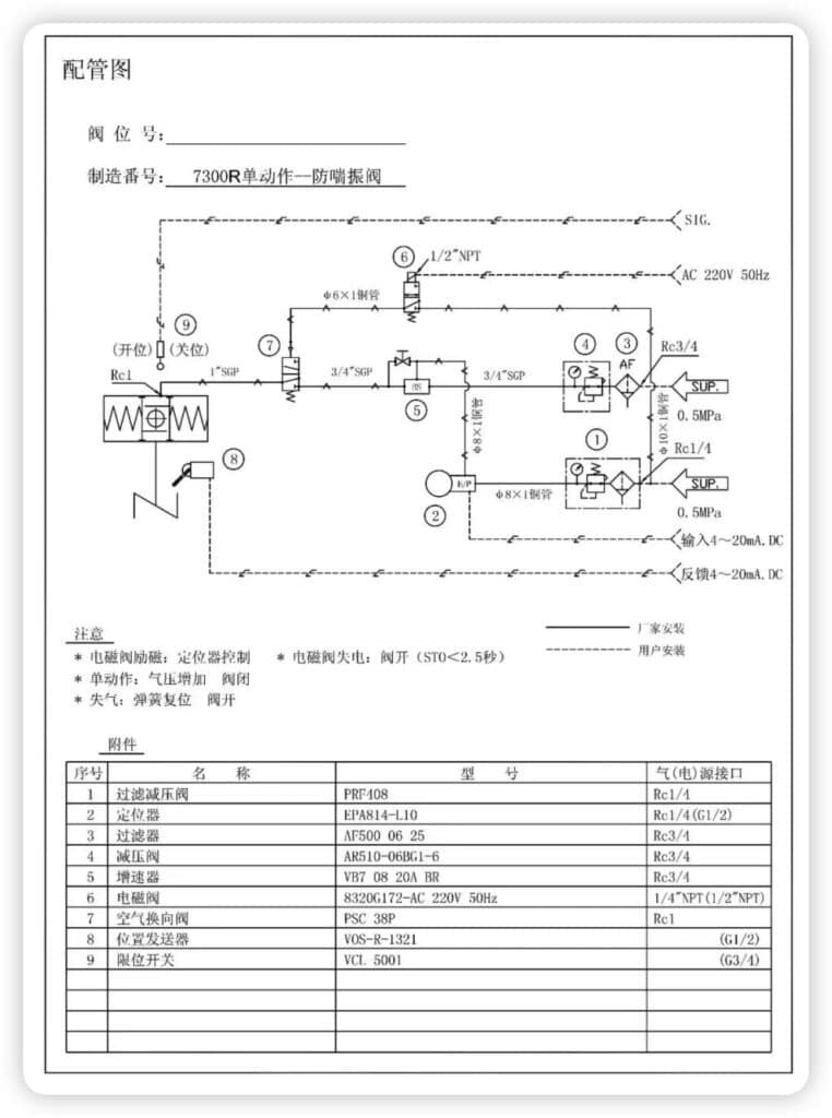
No.
Component Name
Model
Core Function
1
Filter Regulator
PRF408
Filters air impurities and stabilizes pressure, providing clean and stable air supply for the system
2
Positioner
EPA814-110
Receives 4–20 mA DC control signal and outputs corresponding air pressure to drive the valve, enabling precise position control
3
Filter Regulator
AF500-06-25
Secondary filtration and pressure reduction to ensure air quality for downstream components
4
Pressure Regulator
AR510-06BG1-6
Further stabilizes air pressure, supplying suitable pressure for solenoid valves, boosters, etc.
5
Volume Booster
VB7-08-20A-BR
Increases air flow rate, reducing valve actuation time to ≤ 2.5 seconds
6
Solenoid Valve
8320G172-AC 220V 50Hz
Acts as an on/off switch for the air circuit: energized → air path open (positioner control); de-energized → air path closed (valve reset)
7
Air Directional Valve
PSC-38P
Switches air flow direction; works with single-acting actuator to achieve logic: air pressure ↑ → valve closes, air loss → valve opens
8
Position Transmitter
VOS-R-3321
Detects actual valve position and outputs 4–20 mA DC feedback signal for closed-loop control
9
Limit Switch
VCL-5001
Provides feedback of valve “open” and “closed” limit positions (dry contact signal)
Engineering Optimization
The system was reviewed as a complete pneumatic action chain rather than as a single valve.
Key actions included:
simplifying the pneumatic circuit
reducing air path restriction
improving air supply stability
optimizing accessory arrangement for faster response
Result
After optimization:
valve opening time was reduced to < 2 seconds
response became consistent and repeatable
surge protection performance improved
Key Lesson
The limitation was not in the valve itself.
It was in the pneumatic action chain and how it was implemented in the field.
7. The Most Common Failure Modes Engineers Should Expect
When anti-surge valve packages misbehave, the symptoms are usually familiar.
One of the most common is slow response. In the field, this is often caused not by the valve body but by unstable instrument air, clogged filters, sticking solenoids, poor booster performance, leakage, seal wear, or restrictive tubing layout. In many cases, the whole pneumatic circuit is slower than expected, not just the valve.
Another common issue is mismatch between commanded position and actual valve position. Engineers may see that the control system sends the correct signal, yet the valve does not track properly or shows unstable behavior. In those cases, the causes may include positioner setup, linkage looseness, backlash, vibration effects, feedback inaccuracy, or excessive friction, especially at lower openings.
Intermittent sticking is another serious problem. This is dangerous because it may not show up during routine operation. It often appears during functional testing or under upset conditions, exactly when clean movement matters most. The causes may include actuator seal wear, insufficient lubrication, increased packing friction, long idle periods, or hidden air leakage that reduces available force during critical movement.
A further problem is false confidence from end-position feedback. Engineers sometimes see healthy open-close signals and assume the valve is performing correctly. But end-position confirmation does not prove that the valve modulates correctly across the control range. That is why continuous position review and real movement observation matter much more than a simple end-switch status.
Seal wear, poor lubrication, increased packing friction, long idle periods, hidden leakage
Good end-position signal but poor real control behavior
Limit switches only show end status, not true modulating performance
Good bench performance but weak field response
Tubing restriction, site air condition, vibration, accessory mismatch, insufficient actuator margin
8. What Engineers Should Confirm Before FAT or Final Approval
Table 3 — What to Confirm Before Approval
Review Point
Why It Matters
Required recycle capacity
Cv alone may not reflect actual protection ability
Fail action as a function
The full pneumatic and electrical action chain must match the protection philosophy
Stroke time under defined conditions
A number without test conditions is weak engineering evidence
Actuator margin
Prevents performance loss when friction, wear, and field variation increase
Accessory package
Strongly affects dynamic behavior, reliability, and fail performance
Feedback arrangement
End switches alone are often not enough for anti-surge service
Site conditions
Vibration, air quality, accessibility, and maintenance affect long-term behavior
This is where many projects can save time, arguments, and rework.
Before approving an anti-surge valve package, engineers should confirm more than the usual valve basics. At a minimum, the following points deserve direct review:
1. Recycle capacity under realistic conditions
Not only nominal Cv, but whether the package can actually provide the required recycle function under the expected operating envelope.
2. Fail action as a verified function
Not only the written fail position, but how the pneumatic and electrical logic actually produce that movement.
3. Stroke-time claim under defined test conditions
The number should be tied to supply pressure, accessory arrangement, tubing conditions, actuator configuration, and starting position.
4. Actuator margin
Enough margin should exist to overcome friction, wear, process variation, and realistic field resistance over time.
5. Accessory package suitability
The positioner, solenoid, booster, feedback devices, and air preparation should all match the actual duty rather than being treated as default accessories.
6. Site-related practicalities
Vibration, air quality, mounting arrangement, accessibility, and long-term maintenance should be reviewed before the package is released.
From experience, these checks are where many anti-surge packages either become reliable or begin to drift into later project trouble.
9. How THINKTANK Reviews Anti-Surge Valve Duty
For this type of service, THINKTANK does not review the assembly only as a valve body with an actuator attached. We review it as a complete action package.
THINKTANK usually starts with these questions:
What recycle duty is really required?
How much normal modulation is expected?
What fail action is required by the compressor protection philosophy?
What response time is being asked for, and under what conditions?
What is the actual instrument air condition?
What accessory package is required to support both control and protective action?
This approach matters because anti-surge duty is where many technical mismatches hide. A package may look reasonable when only size and rating are reviewed. But once response time, fail action, pneumatic switching logic, accessory matching, and field conditions are considered together, the real strengths and weaknesses become clearer.
That is also why THINKTANK prefers to discuss not only valve type and pressure class, but the whole movement chain. For anti-surge service, that usually gives a more reliable result than treating the assembly as an ordinary valve package.
Engineer’s Checklist for Anti-Surge Valve Review
Before approving an anti-surge valve package, confirm:
the required recycle duty, not just nominal Cv
the fail action on loss of air, loss of power, and trip conditions
the stroke-time claim under defined test conditions
adequate actuator margin for real field resistance
the correct positioner, solenoid, booster, and feedback arrangement
actual instrument air quality and pressure stability
tubing layout and possible pneumatic restrictions
vibration, mounting, and maintenance access at site
FAT scope for both protective action and modulating performance
Conclusion
Anti-surge valve service is difficult for one main reason: the valve has to do two jobs at once.
It must regulate during normal operation, and it must protect the compressor during upset conditions. That is why anti-surge review cannot stop at valve size, Cv, or even basic fail-action labels. The whole package must be considered: valve body, actuator, accessories, pneumatic logic, feedback, field conditions, and protection philosophy.
In real engineering work, the most useful questions are usually not “Can this valve move?” but:
Has the fail action really been verified as a function?
Under what conditions was the stroke time measured?
Is the accessory package matched to the real duty?
Does the pneumatic circuit have any weak points?
Has the package been reviewed as part of compressor protection, not just valve procurement?
Once those questions are answered properly, anti-surge valve design becomes far more solid. And that is usually the point where a valve package stops being just a hardware item and starts becoming a reliable protection solution.
FAQ
What is an anti-surge valve?
An anti-surge valve is a control valve used in compressor protection systems to establish or increase recycle flow when the compressor approaches the surge region. In many systems, it also modulates during normal operation as part of the anti-surge control loop. That is why it must be reviewed as both a control element and a protection element.
Why are anti-surge valves often configured to fail open?
They are often configured this way because the compressor protection logic may require rapid recycle flow during abnormal conditions such as air failure, power failure, or trip events. However, “fail open” should never be assumed without review. The correct fail action must follow the actual protection philosophy of the compressor system.
Why are high-performance butterfly valves commonly used in anti-surge service?
They are commonly used because they can provide high flow capacity, relatively compact structure, and fast quarter-turn movement, especially in large recycle lines. But valve type selection should never be based on architecture alone. The full package still has to be checked for control behavior, fail action, response time, and field reliability.
Why can a valve package meet Cv and still perform poorly in anti-surge duty?
Because Cv only addresses flow capacity. Anti-surge service also depends on fail action, actuator margin, pneumatic circuit design, accessory package quality, feedback arrangement, and realistic response under site conditions. A package with enough Cv can still underperform badly if the movement chain is weak.
What usually causes anti-surge valve packages to fail interlock testing?
Common causes include incorrect pneumatic switching logic, slow or sticking solenoid action, insufficient actuator margin, unrealistic stroke-time assumptions, restrictive tubing layout, poor instrument air quality, and incomplete alignment between datasheet fail action and actual circuit behavior.
Why is the pneumatic accessory package so important?
Because the accessories largely determine how the valve behaves in real service. The solenoid affects the protection switch-over logic. The positioner affects tracking and control stability. The filter regulator affects air quality and pressure stability. Boosters and quick exhaust devices affect response time. Continuous position feedback affects how accurately the control system sees the true valve position.
Why do many anti-surge valves use single-acting pneumatic actuators?
Single-acting actuators are widely used because they make fail-safe movement easier to define and verify. Under loss of air or protective switching conditions, the spring can move the valve toward the required safe position. This is especially useful in compressor protection service, where predictable abnormal-condition behavior matters as much as normal control performance.
What should engineers confirm before accepting stroke-time claims?
They should confirm the test conditions behind the number: supply pressure, actuator size, tubing arrangement, installed accessories, starting valve position, and assumed load. A stroke-time claim without defined test conditions is often much less useful than it appears.
What should engineers review before FAT or final approval of an anti-surge valve package?
They should review recycle capacity, fail action as an actual function, stroke time under defined conditions, actuator margin, accessory suitability, feedback arrangement, pneumatic layout, and site-related factors such as vibration, air quality, and maintenance access.
What is one of the most common mistakes in anti-surge valve selection?
One of the most common mistakes is to treat anti-surge duty as a valve sizing exercise only. In reality, it is a package behavior problem. Engineers usually get much better results when they review the valve body, actuator, accessories, pneumatic logic, and compressor protection philosophy together.
Key Takeaway
Anti-surge valve service should not be reviewed as a valve body selection problem only. In real compressor projects, reliable performance comes from the full package: valve body, actuator, pneumatic logic, accessory matching, and fail-action verification. That is where many packages either become reliable or begin to create trouble later.
After earning my bachelor's degree in mechanical engineering from Zhejiang Normal University in 2008, l was fortunate enough to begin my career with Siemens, Fisher, and YTC, focusing on control valve accessories. Over the past dozen years, l've poured my heart and energy into understanding technology and fluid solutions for control valves.
Now, as the marketing director for THINKTANK, a trusted branch of the Taiwan STONE valve group, I can't help but feel proud of how far we've come. Our knowledge isn't just reaching professionals like engineer and valve distributors; it's also inspiring the next generation of automation college students.
l genuinely hope you're enjoying our articles and finding them helpful. Your thoughts, questions, and feedback mean the world to me, so please don't hesitate to reach out to [email protected]. Whether you're a seasoned expert or just curious about the field, I'm here to connect, share, and learn together.
I am the author of this article, and also the CEO and marketing director of THINKTANK, with 15 years of experience in the industrial valve industry. If you have any questions, you can contact me at any time.
Just fill out your name, email address, and a brief description of your inquiry in this form. We will contact you within 24 hours.
Why are more and more international valve brands choosing THINKTANK for OEM service?
Brand is reputation, which not only requires high valve technology, but also great comercial support and fast response after-sales service and delivery time. They will not gamble their brand on an unknown product
Avoid your inquiry is delay response, please enter your WhatsApp/Wechat/Skype along with the message, so we can contact you at the very first time.
We will reply you within 24 hours. If for urgent case, please add WhatsApp: +86 185 1656 9221, or WeChat: +86 199 2125 0077. or call +86 189 5813 8289 directly.
Get An Instant Quote
Get An Instant Quote
We will reply you within 24 hours. If for urgent case, please add WhatsApp: +86 199 2125 0077, or WeChat: +86 199 2125 0077. Or call +86 189 5813 8289 directly.
Direct to Control Valve Factory With Competitive Price & Reliable Quality
Get An Instant Quote
Just leave your name, email, and simple message or requirements, We will contact you within 1 hour.