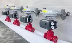
This guide explains how to configure and automatically calibrate an ABB TZIDC or TZIDC-200 digital valve positioner using the local four-button interface.
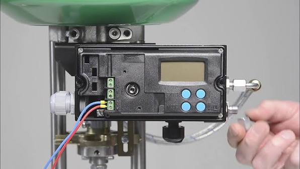
Button Functions
| Button | Function |
|---|---|
| ENTER | Confirm a selection, start an action or save a setting |
| MODE | Select an operating mode, parameter group or parameter |
| ▲ UP | Move upward through the menu or increase a value |
| ▼ DOWN | Move downward through the menu or decrease a value |
On the configuration level, hold MODE and press the arrow buttons to move between parameters. To select another parameter group, hold MODE + ENTER and press ▲ or ▼.
Before Calibration
Confirm that:
- The positioner is correctly mounted.
- The feedback lever or rotary coupling is correctly installed.
- The position feedback shaft remains within its permitted operating range.
- Pneumatic tubing is connected correctly.
- Clean instrument air is available.
- The electrical signal is connected.
- The valve can safely travel through its full stroke.
For linear actuators, the usable feedback span must remain within the positioner’s linear operating range. For rotary actuators, the normal usable feedback span is 90°.
Warning: Auto Adjust moves the valve through its operating range. Isolate the valve from the process before starting calibration.
Auto Calibration Procedure
| Step | Procedure |
|---|---|
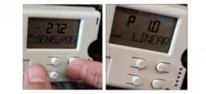
| 1. Enter Configuration Mode | Press and hold ▲ and ▼ simultaneously. Briefly press and release ENTER while continuing to hold both arrow buttons. Wait until the countdown changes from 3 to 0, then release the arrow buttons. The display enters configuration mode at P1.0 ACTUATOR. |
| 2. Select the Actuator Type | At P1.0 ACTUATOR, use ▲ or ▼ to select LINEAR for a linear actuator or ROTARY for a rotary actuator. |
| 3. Select Full Auto Adjust | Hold MODE and press ▲ until P1.2 ADJ_MODE appears. Release MODE, then select FULL. |
| 4. Open Auto Adjust | Hold MODE and use ▲ or ▼ to select P1.1 AUTO_ADJ. Release MODE. |
| 5. Start Auto Adjust | Press and hold ENTER until the countdown changes from 3 to 0. Release ENTER to start calibration. |
| 6. Wait for Completion | The display shows RUN together with the current calibration step. Do not interrupt the signal or air supply. |
| 7. Confirm the Result | When COMPLETE appears, press ENTER to acknowledge the message. |
| 8. Save and Exit | Move to P1.4 EXIT. Select NV_SAVE, then hold ENTER until the countdown reaches 0. The positioner saves the settings and returns to the operating level. |
| 9. Verify Valve Operation | Apply 4, 8, 12, 16 and 20 mA signals. Confirm the valve direction, displayed position and full travel. |
Entering configuration mode requires both arrow buttons to remain pressed until the countdown has finished. In P1.1 AUTO_ADJ, holding ENTER through the countdown starts the selected calibration mode. Settings are permanently stored by leaving the configuration level through EXIT → NV_SAVE.
P1.0 Actuator Type
| Setting | Application |
|---|---|
| LINEAR | Globe valves and other linear-stroke actuators using a feedback lever |
| ROTARY | Ball valves, butterfly valves and other part-turn actuators using rotary feedback |
The setting configures the positioner for the appropriate position-sensor range. ABB specifies approximately ±30° for the linear setting and ±45° for the rotary setting. Run Auto Adjust again whenever the actuator type is changed.
LINEARandROTARYdescribe the actuator and feedback arrangement. They do not determine whether the valve is fail-open or fail-close.
P1.2 Auto Adjust Mode
For initial commissioning, select:
P1.2 ADJ_MODE = FULL
| Setting | Function |
|---|---|
| FULL | Complete calibration |
| STROKE | Determines the end positions and stroke only |
| CTRL_PAR | Determines the control parameters only |
| ZERO_POS | Calibrates the zero position only |
| LOCKED | Auto Adjust is disabled |
A full Auto Adjust determines actuator direction, spring direction, stroke, opening and closing times, control parameters and the I/P module offset.
Auto Adjust Display Sequence
| Display | Function |
|---|---|
| RUN 10 | Saves the fully depressurized actuator position |
| RUN 20 | Saves the fully pressurized actuator position |
| RUN 30–32 | Measures opening and closing stroke times |
| RUN 40–49 | Determines the tolerance band and fast-control parameters |
| RUN 50–59 | Determines the precision-control parameters |
| RUN 200 | Auto Adjust is complete |
| COMPLETE | Calibration completed successfully |
All Auto Adjust status messages other than RUN must be acknowledged by pressing ENTER.
Changing the Signal Direction
Use P2.3 ACTION to change the relationship between the input signal and the defined valve position.
Menu Procedure
- Enter configuration mode.
- Hold MODE + ENTER.
- Press ▲ or ▼ until
P2._ SETPOINTappears. - Release the buttons.
- Hold MODE and select
P2.3 ACTION. - Select
DIRECTorREVERSE. - Move to
P2.8 EXIT. - Select
NV_SAVE. - Hold ENTER until the countdown reaches
0.
The standard TZIDC/TZIDC-200 setpoint group contains P2.0 MIN_RGE, P2.1 MAX_RGE, P2.2 CHARACT, P2.3 ACTION and P2.8 EXIT.
DIRECT and REVERSE
| Setting | 4 mA | 20 mA |
|---|---|---|
| DIRECT | Defined position 0% | Defined position 100% |
| REVERSE | Defined position 100% | Defined position 0% |
When the valve has been configured so that 0% means closed:
DIRECT: 4 mA = closed; 20 mA = openREVERSE: 4 mA = open; 20 mA = closed
ABB defines DIRECT as an increasing relationship between the analog setpoint and position, while REVERSE creates a decreasing relationship.
Important:
P2.3 ACTIONis not the actuator fail action. The valve’s position after loss of air or electrical power depends on the actuator spring arrangement, pneumatic module and tubing configuration.
Setpoint Range and Characterization
For standard 4–20 mA commissioning, retain:
| Parameter | Recommended Setting |
|---|---|
| P2.0 MIN_RGE | 4.0 mA |
| P2.1 MAX_RGE | 20.0 mA |
| P2.2 CHARACT | LINEAR |
| P2.3 ACTION | DIRECT or REVERSE as required |
The TZIDC also supports equal-percentage and user-defined characteristic curves. These should only be selected when required by the control-valve application.
Factory Reset
The original reset procedure must not be used without first placing the positioner in its safe position.
Correct Factory Reset Procedure
- Isolate the valve from the process.
- Enter configuration mode.
- Select parameter group
P11._ FS/IP. - Open
P11.0 FAIL_POS. - Hold ENTER until the countdown reaches
0to activate the safe position. - Select
P11.1 FACT_SET. - Select
FS_LOAD. - Hold ENTER until the countdown reaches
0. - Wait until
COMPLETEappears. - Press ENTER to acknowledge.
- Check that the configured I/P module type matches the module physically installed.
- Return to
P11.0 FAIL_POSand deactivate the safe position. - Save the settings through
EXIT → NV_SAVE. - Reconfigure the actuator type and perform a new full Auto Adjust.
ABB prevents factory settings from being loaded unless FAIL_POS has first been activated. After resetting, the I/P module type must be checked because an incorrect setting may cause the actuator to move rapidly to an end position.
Do not use Factory Reset as a normal troubleshooting step. Use it only when the positioner is being installed on a different actuator or when the previous configuration is no longer usable.
Common Auto Adjust Errors
| Message | Meaning and Checks |
|---|---|
| CALC_ERR | Plausibility check failed. Check mounting, travel and pneumatic connections. |
| OUTOFRNG | Feedback shaft exceeded its permitted sensor range. Correct the linkage or rotary coupling. |
| RNG_ERR | The feedback movement uses less than 10% of the available sensor range. |
| TIMEOUT | Control parameters could not be determined within the permitted time. Check air pressure, friction, leakage and actuator speed. |
| SPR_ERR | The detected actuator spring direction does not match the configuration. |
| BREAK | Auto Adjust was interrupted by the operator. |
These messages are displayed when Auto Adjust cannot complete its mechanical or control-parameter checks.
Final Function Check
After successful calibration, verify:
| Input Signal | Expected Position with DIRECT* |
|---|---|
| 4 mA | 0% |
| 8 mA | 25% |
| 12 mA | 50% |
| 16 mA | 75% |
| 20 mA | 100% |
*Assuming a 4–20 mA full range, linear characterization and no split-range configuration.
Confirm that:
- The valve moves in the correct direction.
- The displayed position agrees with the mechanical valve position.
- The valve reaches both end positions.
- Movement is smooth and stable.
- No active alarm or calibration error remains.
- The positioner has returned to automatic control.
Quick Setup Sequence
▲ + ▼ → Press ENTER → Countdown 3–0 → P1.0 ACTUATOR → P1.2 FULL → P1.1 AUTO_ADJ → Hold ENTER → COMPLETE → P1.4 EXIT → NV_SAVE