
In many storage tank projects, tank blanketing and breather valves appear to be simple components. The calculation looks straightforward, the pressure range is low, and the valves are often treated as secondary items.
Yet in real operation, pressure instability, frequent regulator hunting, unexpected vacuum alarms, and excessive nitrogen consumption are repeatedly traced back to the same root cause: the tank blanketing system was sized using outdated assumptions.
Over the past years, we have reviewed many projects where the valve itself was not the problem. The issue was that the breathing demand of the tank was underestimated, especially for volatile liquids and warm operating environments.
This is exactly where API 2000 7th Edition changes the engineering outcome. Not by changing physics, but by forcing engineers to account for real operating conditions rather than simplified averages.
What Is Tank Blanketing and Why It Matters
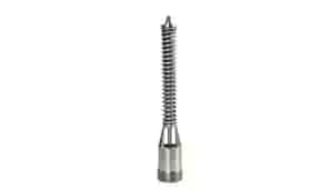
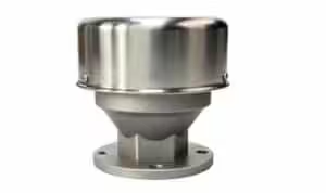
From an engineering point of view, tank blanketing is not a protective accessory. It is a pressure control loop operating at very low pressure.
When a tank is pumped out, or when the vapor space cools, the blanketing regulator must respond immediately. If it does not, the tank will see negative pressure long before any safety device reacts.
Most field issues do not occur at maximum flow. They occur during small pressure changes, where the regulator is expected to control smoothly. This is why blanketing systems that look acceptable on a datasheet often fail in actual service.

In-Breathing and Out-Breathing in Storage Tanks
Every storage tank operates in two basic modes: in-breathing and out-breathing.
In-breathing occurs during pump-out or vapor space cooling. This condition defines the required capacity and response of the tank blanketing regulator. Out-breathing occurs during pump-in or vapor space heating and defines the required capacity of the breather valve or vapor recovery regulator.
The mistake often made in design is treating these two conditions separately. In practice, they interact. An undersized breather valve can disturb blanketing control, and an undersized blanketing regulator will amplify pressure fluctuations during filling and emptying cycles.
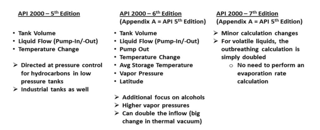
Why API 2000 7th Edition Changes Valve Sizing Results
API 2000 5th Edition is still widely used because it is simple and familiar. However, it assumes average conditions that rarely exist in real operation.
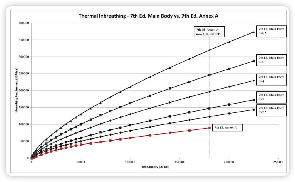
Starting from the 6th Edition and carried into the 7th Edition, API 2000 introduced average storage temperature, vapor pressure, and geographic latitude into the calculation. This change was not academic. It was driven by repeated underestimation of breathing demand, particularly for volatile liquids.
In practical terms, tanks operating in warm climates or storing high vapor pressure products require significantly more in-breathing capacity than older calculations predict. Engineers often see this only after commissioning, when pressure instability becomes visible.
Tank Blanketing Regulator Sizing Considerations
Under API 2000 7th Edition, in-breathing demand is no longer dominated by pump-out rate alone. Thermal contraction of the vapor space becomes a major contributor, especially as tank size increases.
This is where many blanketing regulators are unintentionally undersized. They may pass the calculated maximum flow, but they lack sufficient control margin at low differential pressure. As a result, the regulator operates near its limit, leading to slow response and unstable pressure control.
From experience, blanketing regulators should be sized with control stability in mind, not just flow capacity. A regulator that is slightly larger but operates comfortably within its control range will always outperform a marginally sized unit.
Breather Valve and Vapor Recovery Regulator Sizing
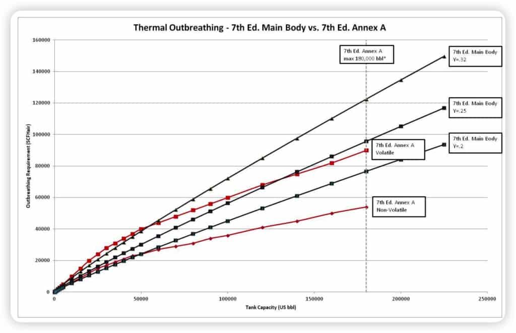
The impact of API 2000 7th Edition on out-breathing is generally smaller than on in-breathing, but it should not be ignored.
For volatile liquids, the standard simplifies the calculation by effectively doubling the pump-in contribution. In fast filling scenarios, breather valves sized using older methods may restrict vapor release, causing internal pressure to rise unnecessarily.
While breather valves are often treated as safety devices, they also influence normal operating pressure behavior. Proper sizing reduces unnecessary cycling and improves overall system stability.
New Variables: C-Factor and Y-Factor — What Actually Changed for Engineers
Starting from API 2000 6th Edition and retained in the 7th Edition, the standard introduced two new correction factors: C-Factor and Y-Factor. Their purpose is not to complicate the calculation, but to correct a long-standing underestimation of tank breathing demand under real operating conditions.
Both factors are linked to geographic latitude, because large-scale weather patterns and ambient temperature variations have a measurable impact on tank vapor space behavior. API 2000 divides latitude into three bands: below 42°, between 42° and 58°, and above 58°.
The C-Factor is used for in-breathing calculations, which determine the required capacity of the tank blanketing regulator. Unlike earlier editions, C-Factor does not depend on latitude alone. It also increases with higher vapor pressure and higher average storage temperature. In practical terms, this means tanks storing volatile liquids in warm, low-latitude regions experience much stronger thermal contraction effects than previously assumed. As a result, in-breathing demand — and therefore blanketing regulator capacity — can increase significantly.
The Y-Factor, by contrast, is used only for out-breathing calculations when sizing breather valves or vapor recovery regulators. Y-Factor depends solely on latitude and reflects differences in ambient heating of the vapor space. Compared to C-Factor, its impact is generally smaller and more predictable.
The key engineering takeaway is simple:
C-Factor mainly drives the increase in blanketing regulator size, while Y-Factor provides a moderate correction for breather and vapor recovery sizing. Ignoring these factors, especially for volatile liquids and warm climates, is a common reason why blanketing systems appear correct on paper but become unstable in real operation.
C-Factor — Used for In-Breathing Calculations (Tank Blanketing Regulator Sizing)
| Latitude Zone | Vapor Pressure Condition | Avg. Storage Temp < 77°F | Avg. Storage Temp ≥ 77°F |
|---|---|---|---|
| Below 42° | Vapor pressure similar to Hexane | 4.0 | 6.5 |
| Below 42° | Vapor pressure higher than Hexane or unknown | 6.5 | 6.5 |
| 42° – 58° | Vapor pressure similar to Hexane | 3.0 | 5.0 |
| 42° – 58° | Vapor pressure higher than Hexane or unknown | 5.0 | 5.0 |
| Above 58° | Vapor pressure similar to Hexane | 2.5 | 4.0 |
| Above 58° | Vapor pressure higher than Hexane or unknown | 4.0 | 4.0 |
Y-Factor — Used for Out-Breathing Calculations (Breather Valve / Vapor Recovery Regulator)
| Latitude Zone | Y-Factor |
|---|---|
| Below 42° | 0.32 |
| 42° – 58° | 0.25 |
| Above 58° | 0.20 |
Sizing Calculation for a Tank Blanketing Regulator (Engineering Validation)
To understand why API 2000 7th Edition often leads to larger blanketing regulators, it is useful to look at the sizing calculation itself—not in theory, but in the way it is applied in real projects.
For in-breathing conditions, API 2000 defines the required blanketing flow as the sum of two components:
- Gas required to replace liquid being pumped out of the tank
- Gas required to compensate for thermal contraction of the vapor space
In simplified form, the calculation can be expressed as:
Tank blanketing regulator flow = pump-out component + thermal contraction component
What changed in the 6th and 7th Editions is not the structure of this equation, but the weight of the thermal term.
Under API 2000 7th Edition, the thermal contraction component is calculated using the C-Factor, which incorporates latitude, vapor pressure, and average storage temperature. For large tanks or volatile liquids, this term can become dominant, often exceeding the pump-out contribution.
This explains a common field observation:
even when pump-out rates are modest, the calculated blanketing flow can be surprisingly high. In many cases reviewed after commissioning, the blanketing regulator was sized correctly for pump-out, but underestimated the thermal in-breathing requirement.
A worked example in the guideline shows that for a 50,000-barrel tank operating below 42° latitude, with unknown or high vapor pressure and an average storage temperature above 77 °F, the calculated blanketing demand exceeds 130,000 SCFH, despite a pump-out rate of only 100 GPM.
From an engineering perspective, this calculation validates two important points:
- The C-Factor directly drives blanketing regulator size under the latest standard
- Thermal effects can no longer be treated as a secondary correction for large or volatile storage tanks
This is why blanketing regulators sized using older API 2000 methods often appear adequate on paper, yet struggle to maintain stable pressure in real operation.
Breather Valve Sizing (Out-Breathing) per API 2000 7th Edition
In API 2000, the out-breathing sizing method is presented as a calculation for a vapor recovery regulator. In non-recovery systems, the same out-breathing demand is also the engineering basis for selecting breather valve (P/V relief valve) capacity.
Out-breathing is driven by two contributors: (1) vapor displaced by liquid pump-in and (2) vapor space expansion due to temperature rise. API 2000 7th Edition provides two equations, depending on whether the stored liquid is non-volatile or volatile:
Non-volatile liquids
Out-Breathing Flow = Pump-In Term + Thermal Expansion Term
= (8.02 × Maximum Pump-In Rate) + [1.51 × Y-Factor × (Tank Volume × 5.618)^0.9 × Insulation Factor]
Volatile Liquids
Out-Breathing Flow = Pump-In Term + Thermal Expansion Term
= (16.04 × Maximum Pump-In Rate) + [1.51 × Y-Factor × (Tank Volume × 5.618)^0.9 × Insulation Factor]
The key simplification in the 7th Edition is that for volatile liquids the pump-in term doubles (8.02 → 16.04), meaning volatile liquids result in roughly twice the pump-in contribution compared with non-volatile liquids. Y-Factor is latitude-based only, so its influence is generally more moderate than the C-Factor used for in-breathing calculations.
Conclusion: Applying API 2000 in Real Projects
API 2000 7th Edition does not introduce new physics. What it changes is the margin of error.
In many modern projects, especially those involving volatile liquids or warm operating environments, older sizing methods underestimate breathing demand. The result is not immediate failure, but long-term operational instability.
For engineers, the key lesson is straightforward: tank blanketing and breather valves must be sized for real operating conditions, not simplified assumptions. Applying the latest API 2000 guidance with engineering judgment leads to more stable tanks, lower operating issues, and fewer surprises after commissioning.
Additional Engineering Clarification: Interpreting API 2000 for Nitrogen-Blanketed Tanks
After reviewing API 2000 7th Edition, some engineers raise a practical follow-up question: if the standard expresses the normal breathing requirement on an air-equivalent basis, how should this be understood in a nitrogen-blanketed tank?
The key point is that API 2000 first defines the tank breathing demand on a common reference basis. In other words, the standard first tells us how much gas replacement capacity the tank requires during liquid transfer and thermal breathing. It does not begin by sizing the actual nitrogen supply line or the final regulator trim under plant operating conditions.
For a nitrogen-blanketed tank, the Section 3.3.2 result should therefore be understood as the engineering basis for determining the required nitrogen make-up capacity. Once the required breathing demand is established on the API reference basis, the engineer can then evaluate the actual nitrogen supply conditions, including upstream pressure, temperature, regulator differential pressure, and available control margin.
This distinction is important in practice. A system may appear adequate when the breathing demand is viewed only as a reference-basis flow, yet still perform poorly if the available nitrogen supply pressure is unstable or if the regulator is selected too close to its operating limit. From a field perspective, many blanketing problems are not caused by the API calculation itself, but by the gap between the calculated tank demand and the actual behavior of the nitrogen supply system.
Another common follow-up question concerns Appendix F. Engineers sometimes notice that Appendix F can lead to lower values than the normal in-breathing calculation and ask whether the blanketing flow from Section 3.3.2 can therefore be reduced.
In engineering terms, the answer is no, because the two parts of the standard do not serve the same purpose.
Section 3.3.2 is used to determine the normal breathing demand of the tank during operation. This is the basis for sizing the blanketing regulator so the tank can remain protected during pump-out and thermal contraction. Appendix F, by contrast, addresses inert-gas blanketing from the standpoint of flashback protection. It is a separate layer of design consideration focused on ignition and flame propagation risk, not a replacement for normal venting or blanketing sizing.
This means a blanketed tank may still require Appendix F review even when nitrogen blanketing is already provided. The reason is simple: blanketing reduces the likelihood of a flammable atmosphere, but system protection philosophy may still require additional consideration of operating reliability, inert-gas continuity, instrumentation, or flame arrester arrangement.
The practical takeaway is straightforward:
- Section 3.3.2 defines the tank’s normal breathing demand.
- The blanketing system must be sized to meet that demand under real operating conditions.
- Appendix F should be reviewed separately when flashback protection is part of the project safety philosophy.
For real projects, engineers should not treat these calculations as interchangeable. One addresses normal tank breathing performance. The other addresses an additional protection objective. Understanding that distinction helps avoid both undersized blanketing systems and unnecessary confusion during design review.