Case Summary
| Item | Case Information |
| Application | Cryogenic liquid oxygen service at approximately −196°C |
| Valve ownership | The valve was supplied by another manufacturer |
| Installation | Outdoor installation |
| Valve configuration | Pneumatic diaphragm actuator, air-to-close operation, flow-to-open trim, extended cryogenic bonnet and composite V-PTFE packing |
| Main symptom | The valve could stick at different positions throughout its complete 0% to 100% travel range |
| Video test point | A 16 mA command represented 75% of the configured travel scale, while 20 mA corresponded to the fully closed position |
| Observed movement | The stem remained stationary, suddenly broke away, travelled beyond the target and was then repeatedly corrected by the positioner |
| Diagnostic direction | Excessive mechanical resistance in the stem, packing or related guiding system |
| Temporary field result | After a very small amount of approved oxygen-compatible low-temperature lubricant was applied to the external stem under the owner’s controlled procedure, the valve moved smoothly and the hunting disappeared |
| Most likely cause | Excessive full-stroke stem and packing resistance relative to the available actuator breakaway thrust |
| Permanent requirement | Inspect the packing, stem condition, mechanical alignment and guide system, and recalculate the actuator thrust margin |
A customer recently contacted THINKTANK team regarding a cryogenic control valve supplied by another manufacturer.
The original valve manufacturer had not provided an effective solution, so the customer sent us several operating videos, valve information and a detailed description of the field problem and asked whether we could help diagnose it.
The valve was installed outdoors in liquid oxygen service at approximately −196°C.
It had the following configuration:
- Pneumatic diaphragm actuator;
- Air-to-close operation;
- Flow-to-open valve trim;
- Extended cryogenic bonnet;
- Composite V-PTFE packing;
- 20 mA corresponding to the closed position;
- Modulating operation throughout the complete valve stroke.
The valve experienced severe sticking at different positions throughout its entire 0% to 100% travel range.
The Operating Problem
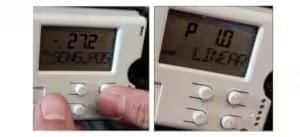
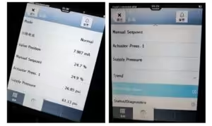
One of the videos showed the valve being commanded to 75% of its configured travel scale.
According to the signal scaling used at the site, a 16 mA signal represented the required 75% travel position, while 20 mA corresponded to the fully closed position.
When the 16 mA command was applied, the valve stem initially remained stationary.
After several seconds, the stem suddenly broke away and moved beyond the commanded position. The positioner then attempted to return the valve to the 75% target, but the stem could stick and suddenly move again during the correction.
This resulted in repeated hunting and unstable valve travel.
The 75% position shown in the video was only one representative example. According to the customer, similar sticking could occur at different positions throughout the complete 0% to 100% stroke.
Control command changes → valve stem remains stationary → actuator force increases → static friction is overcome → valve suddenly jumps → valve overshoots the target → positioner reverses its output → valve sticks again.
This was an important diagnostic detail.
The problem was therefore not limited to one particular valve opening or one fixed point of mechanical interference. The investigation had to consider components that could resist stem movement throughout the complete valve stroke.
Possible Causes Considered
Based on the customer’s operating information and videos, we considered the complete valve, actuator and positioner assembly rather than immediately assuming that the positioner was defective.
| Possible Cause | Recommended Verification | Diagnostic Interpretation |
| Insufficient or unstable instrument-air pressure | Measure the pressure at the filter regulator outlet, positioner supply port, positioner output port and actuator chamber during valve movement | Low or unstable supply pressure may reduce available actuator thrust and make an existing friction problem more severe |
| Leakage from pneumatic tubing or fittings | Inspect all tubing, fittings and pneumatic connections and perform a pressure-decay test where appropriate | Leakage may prevent the actuator from developing or maintaining sufficient thrust |
| Actuator diaphragm leakage | Pressurize and isolate the actuator chamber, then monitor pressure and stem position | Abnormal pressure decay may indicate diaphragm or casing leakage |
| Incorrect positioner action or calibration | Verify direct or reverse action, zero, span, feedback direction and actual travel indication | Incorrect configuration may cause unstable movement, but it does not normally explain delayed breakaway after the stem remains stationary |
| Positioner feedback-linkage problem | Inspect the feedback arm, linkage geometry, mechanical connection and looseness | Incorrect or loose feedback may create inaccurate position indication or unstable correction |
| Foreign material or localized trim damage | Determine whether sticking repeatedly occurs at the same travel position | A repeatable fixed-position problem may indicate foreign material, damaged trim or localized interference |
| Plug or guide friction | Inspect guide surfaces, clearances, scoring, galling and cryogenic contraction effects | Guide resistance may contribute, especially if contact or misalignment exists throughout the stroke |
| Stem, bonnet or actuator misalignment | Check the alignment of the actuator stem, connector, valve stem, bonnet, packing box and trim | Misalignment can create side loading and continuous resistance throughout the valve travel |
| Excessive packing compression or friction | Inspect packing installation, compression, deformation and stem condition; measure breakaway pressure in both directions | Excessive packing friction can cause the stem to remain stationary until actuator thrust exceeds the breakaway resistance |
| Insufficient actuator breakaway-thrust margin | Calculate the available actuator thrust and compare it with packing, guide, spring and process forces | The actuator may eventually move the valve but may not have sufficient margin to initiate movement smoothly |
Step 1: Confirm the Control Signal and Valve Action
The first step was to confirm that the valve, actuator and positioner action were correctly configured.
The customer was asked to verify:
- Whether 4 mA and 20 mA represented the correct valve positions;
- Whether the displayed percentage represented percentage open or percentage closed;
- Whether the positioner was configured for the correct direct or reverse action;
- Whether the actuator was actually operating as air-to-close;
- Whether the DCS signal matched the local positioner command;
- Whether the position feedback corresponded to the actual stem position; and
- Whether the feedback linkage was correctly installed and securely connected.
An incorrect positioner action or reversed feedback setting can cause unstable valve movement.
However, this type of configuration error does not normally explain a valve that remains completely stationary for several seconds and then suddenly jumps after force has accumulated.
The delayed breakaway movement indicated that a mechanical resistance problem was more likely.
Step 2: Check the Instrument-Air Supply
The next step was to verify the complete pneumatic supply system.
The customer was advised to measure the pressure at:
- The filter regulator outlet;
- The positioner supply connection;
- The positioner output connection; and
- The actuator diaphragm chamber.
The pressure should be monitored not only while the valve is stationary, but also during the moment when the valve sticks and suddenly begins to move.
This pressure trend can provide very useful diagnostic evidence.
If the positioner output pressure continues to increase while the valve stem remains stationary, and the stem suddenly moves only after the pressure reaches a certain level, this indicates that the actuator is building force to overcome static mechanical friction.
The customer was also advised to check:
- Air tubing;
- Tube fittings;
- Positioner connections;
- Filter regulator;
- Pneumatic accessories; and
- Actuator casing connections.
Any leakage in the pneumatic system may reduce the available actuator force and make an existing friction problem more severe.
Step 3: Check the Pneumatic Diaphragm Actuator
A damaged or leaking actuator diaphragm was another possible cause.
To verify the actuator condition, the pneumatic chamber should be pressurized and isolated in accordance with the site’s maintenance procedure.
The following items should then be checked:
- Whether the actuator pressure can be maintained;
- Whether the pressure decreases abnormally;
- Whether the stem position changes while the pressure is held constant;
- Whether there is leakage around the diaphragm casing;
- Whether the actuator spring moves smoothly;
- Whether the actuator stem is bent or misaligned; and
- Whether the stem connector introduces side loading.
If the diaphragm cannot maintain pressure, the actuator may not be able to generate stable thrust.
However, actuator leakage normally causes slow movement, failure to reach the commanded position or inability to maintain position.
The sudden breakaway and overshoot observed in the video were more characteristic of mechanical stiction.
Step 4: Verify the Positioner and Feedback System
The positioner was evaluated as one possible contributor to the unstable movement.
The recommended checks included:
- Zero and span calibration;
- Full-stroke calibration;
- Direct or reverse action;
- Input-current accuracy;
- I/P converter response;
- Positioner output-pressure response;
- Feedback-arm geometry;
- Feedback-linkage tightness; and
- Agreement between indicated travel and actual valve travel.
Where permitted by the site’s procedure, the actuator can also be operated using a controlled pneumatic signal independently of the positioner.
If the valve continues to stick when the actuator is operated directly, the positioner is unlikely to be the primary cause.
In this case, the positioner may simply have been responding to an underlying mechanical position error. Recalibration or tuning alone would therefore not eliminate excessive stem, packing or guide resistance.
Step 5: Determine Whether the Resistance Was Localized
Foreign material, damaged valve trim or incorrect guide clearances can also cause a control valve to stick.
The customer was therefore advised to observe whether the sticking repeatedly occurred at one fixed travel position.
If the valve always sticks at the same point, possible causes may include:
- Foreign material between moving components;
- Damage to the valve plug;
- Damage to the guide surface;
- Scoring or galling;
- Incorrect cryogenic guide clearance;
- Thermal distortion;
- A damaged valve seat;
- A bent valve stem; or
- Localized mechanical interference.
However, in this case, the sticking could occur at different positions throughout the complete 0% to 100% valve stroke.
This made a single localized obstruction less likely.
It did not completely eliminate the possibility of guide friction or misalignment, but it shifted the focus toward resistance that acts continuously throughout the valve travel.
Step 6: Investigate the Stem, Packing and Alignment
The valve had an extended cryogenic bonnet with a composite V-PTFE packing arrangement.
An extended bonnet is commonly used to keep the packing sufficiently far away from the extremely low process temperature.
However, an extended bonnet alone does not guarantee low-friction operation.
The actual valve performance still depends on many design and assembly details, including:
- Actual temperature at the packing location;
- Packing material;
- Packing arrangement;
- Packing installation direction;
- Packing-gland compression;
- Static packing friction;
- Dynamic packing friction;
- Stem diameter;
- Stem surface finish;
- Stem hardness;
- Stem straightness;
- Bonnet alignment;
- Actuator alignment;
- Guide clearance;
- Side loading on the stem;
- Outdoor contamination;
- Moisture or icing;
- Process differential pressure; and
- Available actuator thrust.
Packing friction acts throughout the complete stem movement.
If the packing is compressed too tightly, the stem surface is rough or damaged, the actuator and valve are not correctly aligned, or the packing friction is higher than originally estimated, the valve may stick at any position between fully closed and fully open.
The exact sticking position may vary from one movement to another.
This is because the total valve resistance is affected by:
- Previous travel direction;
- Packing deformation;
- Stem condition;
- Actuator spring force;
- Process force;
- Temperature;
- Stem alignment; and
- Static friction history.
Why the Valve Could Suddenly Jump at Any Point in Its Stroke
The sudden movement was not necessarily caused by one fixed obstruction at a particular valve position.
The dominant resistance was associated with components that influence stem movement throughout the complete stroke, particularly the stem-packing system, although guide friction, side loading and mechanical misalignment could also contribute.
Whenever the valve stem stops at any position between 0% and 100% travel, it must overcome breakaway resistance before it can begin moving again.
When the commanded position changes, the positioner detects the difference between the target position and the actual stem position. It then adjusts its pneumatic output in the direction required to reduce this position error.
However, if the available incremental actuator thrust is initially insufficient to overcome the stem, packing and guide resistance, the valve stem remains stationary.
While the stem remains restrained, the actuator chamber pressure continues to change and the net force acting on the stem gradually increases.
The compressed air in the actuator chamber and the elastic deformation of the actuator diaphragm, spring, packing and mechanical linkage can also store energy while the stem remains stuck.
Once the actuator’s net thrust exceeds the breakaway resistance, the stem suddenly begins to move.
The effective resistance after movement begins is typically lower than the resistance required to initiate movement. At the same time, the actuator chamber pressure and positioner output cannot change instantaneously.
For a brief period after breakaway, the available net actuator thrust may therefore be greater than the thrust required to keep the valve moving.
This causes the stem to accelerate rapidly and jump beyond the commanded position.
The positioner then detects that the actual valve-position feedback has passed the target. It reduces or reverses its pneumatic output in an attempt to return the valve to the required position.
During this correction, the stem may stop again. Once stationary, it must again overcome breakaway resistance before movement can restart.
The sequence may then repeat in the opposite direction:
Position error develops → positioner output changes → stem remains stuck → actuator pressure and net thrust increase → breakaway resistance is exceeded → stem suddenly moves → valve overshoots → positioner corrects in the opposite direction → stem sticks again.
Because packing and stem-related resistance act throughout the complete valve stroke, this stick-slip behavior can occur at any position between 0% and 100% travel.
The severity does not have to be identical at every position. It may vary with:
- Travel direction;
- Actuator spring force;
- Process force;
- Packing deformation;
- Guide contact;
- Stem alignment;
- Temperature; and
- The valve’s previous movement history.
In the video, the valve was commanded to 75% of its configured travel scale using a 16 mA signal.
However, the 75% position was only one example. According to the customer, the same sticking and sudden breakaway behavior could occur at different positions throughout the complete valve stroke.
The Decisive Field Test
After reviewing the videos and the preliminary checks, the diagnosis increasingly pointed toward excessive resistance in the stem and packing area.
Under the plant owner’s controlled oxygen-service maintenance procedure, the valve was moved to the fully open position.
The exposed stem surface was cleaned and inspected.
A very small amount of specially approved oxygen-compatible, low-temperature lubricant was then applied in a thin layer to the external stem surface.
The valve was carefully cycled again.
After this temporary treatment:
- The valve moved smoothly throughout its stroke;
- The stem followed the control signal more continuously;
- The previous sticking was no longer observed;
- The sudden breakaway movement disappeared;
- Position overshoot was significantly reduced; and
- The repeated hunting stopped.
This result strongly indicated that the dominant resistance originated in the stem, packing or packing-gland area.
The test did not necessarily prove that the packing material itself was unsuitable.
The excessive friction may have resulted from one or more combined factors, such as:
- Excessive packing compression;
- Dry friction between the stem and packing;
- Unsuitable stem surface finish;
- Stem contamination;
- Actuator and bonnet misalignment;
- Side loading;
- Packing deformation;
- Incorrect packing installation;
- Guide resistance; or
- Insufficient actuator thrust allowance.
Why Lubrication Was Only a Temporary Solution
Although the temporary treatment restored smooth valve movement, it did not eliminate the root cause.
The lubricant may gradually be displaced, removed or lose its effectiveness during repeated stem movement.
The same sticking problem may therefore return after continued operation, although the actual recurrence period cannot be predicted without further field observation.
For liquid oxygen service, lubrication must also be treated with extreme caution.
Ordinary oil or grease must never be applied to a liquid oxygen valve.
Any lubricant used near oxygen service must be specifically approved for:
- Oxygen compatibility;
- Operating pressure;
- Operating temperature;
- Required cleanliness level; and
- The plant owner’s oxygen-service procedure.
The possibility of lubricant migrating along the stem toward an oxygen-contact area must also be evaluated.
For this reason, the field treatment should be regarded only as a controlled diagnostic measure and temporary operational improvement, not as a permanent repair method.
The Most Likely Root Cause
Based on the full-stroke sticking symptom, the diagnostic process and the result of the controlled field test, the dominant resistance most likely originated in the stem, packing or packing-gland area.
The temporary reduction in friction allowed the valve to move smoothly throughout its stroke and stopped the repeated hunting. This strongly supported a mechanical-friction diagnosis.
However, the field result did not prove that the packing material itself was unsuitable, nor did it independently confirm that the actuator was incorrectly sized.
The excessive resistance may have resulted from one or more combined factors:
- Excessive packing compression;
- Dry friction between the stem and packing;
- Packing deformation;
- Incorrect packing installation;
- Unsuitable stem surface finish;
- Stem contamination;
- Actuator and bonnet misalignment;
- Side loading on the stem; or
- Guide resistance.
The available actuator breakaway-thrust margin may also have been insufficient relative to the actual mechanical resistance.
A permanent conclusion therefore requires physical inspection, breakaway-pressure measurement and a complete actuator-thrust calculation.
Was the Absence of a Bellows Seal the Main Problem?
The valve used an extended bonnet with conventional composite packing rather than a bellows-sealed bonnet.
However, it would not be technically accurate to conclude that the valve stuck simply because it did not use a bellows seal.
Extended-bonnet valves with conventional packing are widely used in cryogenic service.
They can operate successfully when the following factors are properly considered:
- Packing temperature;
- Packing material;
- Packing compression;
- Stem finish;
- Stem alignment;
- Guide friction;
- Cryogenic contraction;
- Process force; and
- Actuator thrust margin.
A bellows-sealed design may reduce external leakage risk and change the stem-sealing arrangement, but it also introduces bellows spring force, fatigue considerations, pressure limitations and additional actuator-thrust requirements.
The permanent solution must therefore be based on the complete valve design and force calculation, rather than simply replacing conventional packing with a bellows seal.
Recommended Permanent Corrective Actions
To eliminate the problem at its source, the complete valve and actuator assembly should be inspected and recalculated.
The recommended corrective actions include:
1. Inspect the Complete Packing Set
The packing should be removed and inspected for:
- Incorrect installation or ring orientation;
- Excessive compression;
- Uneven deformation;
- Surface damage;
- Contamination;
- Hardening; and
- Suitability for the specified liquid oxygen service.
The packing-gland loading should also be checked against the packing manufacturer’s recommended assembly requirements.
2. Inspect the Valve Stem
The stem should be inspected for:
- Scratches;
- Scoring;
- Corrosion;
- Surface contamination;
- Incorrect surface roughness;
- Insufficient surface hardness;
- Bending; and
- Dimensional inconsistency.
A damaged, contaminated or excessively rough stem surface can significantly increase packing friction throughout the entire stroke.
3. Verify Mechanical Alignment
The alignment of the following components should be checked:
- Actuator;
- Actuator stem;
- Stem connector;
- Valve stem;
- Bonnet;
- Packing box;
- Valve plug; and
- Guide components.
Even a small alignment error can introduce side loading and increase resistance throughout the complete valve travel.
The valve should also be checked for external piping loads that could distort the valve body or bonnet assembly.
4. Measure Breakaway Pressure Throughout the Stroke
The actuator pressure required to initiate movement should be measured at several positions and in both travel directions.
Recommended test points include:
- Near 0% travel;
- At 25% travel;
- At 50% travel;
- At 75% travel; and
- Near 100% travel.
The test should record:
- Input signal;
- Positioner output pressure;
- Actuator chamber pressure;
- Actual stem position;
- Direction of travel; and
- Breakaway pressure.
This will help determine whether the resistance is relatively constant or changes with valve position and movement direction.
5. Recalculate the Actuator Thrust
The actuator should be recalculated independently for both opening and closing directions.
The calculation should include:
- Packing friction;
- Guide friction;
- Stem-seal resistance;
- Actuator spring force;
- Process differential pressure;
- Valve unbalanced force;
- Flow direction;
- Required seat load;
- Minimum available instrument-air pressure;
- Mechanical efficiency;
- Temperature effects; and
- An appropriate engineering safety margin.
Because the valve is flow-to-open, process forces may assist movement in one direction and oppose movement in the other.
The actuator must therefore have sufficient breakaway and running-thrust margin throughout the complete stroke and in both directions.
6. Review the Packing and Stem-Sealing Design
Depending on the inspection and calculation results, possible improvements may include:
- Correcting the packing installation;
- Reducing excessive packing compression;
- Using a qualified lower-friction packing arrangement;
- Improving the packing geometry;
- Using live-loaded packing where appropriate;
- Improving the stem surface finish or treatment;
- Improving stem guidance;
- Correcting mechanical alignment;
- Increasing actuator capacity; or
- Selecting another qualified stem-sealing design.
A bellows-sealed arrangement should not automatically be treated as the only solution. It must be evaluated against the actual leakage requirements, bellows spring force, fatigue life, pressure conditions and additional actuator-thrust requirements.
The final solution should be verified through engineering calculations and controlled testing for the specified oxygen service.
What This Case Teaches Us
When purchasing a control valve, it is easy to focus on the information that can be clearly seen on a datasheet:
- Valve size;
- Pressure rating;
- Body material;
- Trim material;
- Flow coefficient;
- Positioner brand;
- Solenoid valve;
- Limit switches;
- Air filter regulator; and
- Other accessories.
However, reliable valve operation often depends on engineering details that are not immediately visible:
- Static friction;
- Dynamic friction;
- Fluid viscosity;
- Packing compression;
- Stem resistance;
- Guide resistance;
- Thermal contraction;
- Material stress;
- Valve unbalanced force;
- Breakaway thrust;
- Minimum air-supply pressure; and
- Actuator safety margin.
These hidden parameters determine whether a control valve will respond smoothly and accurately under actual operating conditions.
A valve may have the correct body material, pressure class, actuator and positioner, but still fail to control properly if the friction and force balance have not been carefully evaluated.
This is why selecting a control valve should not be limited to comparing visible accessories and datasheet specifications.
The unseen engineering details must also be protected.
That is the responsibility of professional control-valve engineers.
Conclusion
This liquid oxygen control valve did not stick only at one opening.
It could stick at different positions throughout its entire 0% to 100% travel range.
The 16 mA command corresponding to 75% of the configured travel scale was only one example of the wider problem.
Through a systematic diagnostic process, the possible causes were gradually narrowed down from the air supply, actuator and positioner to the mechanical resistance within the valve assembly.
The temporary reduction in stem and packing friction restored smooth valve movement, confirming that excessive mechanical friction was the dominant cause.
However, the temporary treatment did not correct the original design or force-margin problem.
The permanent solution requires a complete review of:
- Packing condition;
- Packing compression;
- Stem finish;
- Mechanical alignment;
- Guide resistance;
- Cryogenic effects;
- Process forces; and
- Available actuator breakaway thrust.
A reliable control valve is not defined only by what appears on the datasheet.
Its real performance is determined by the engineering details that remain unseen until the valve is operating in the field.
Safety Notice
This case describes a controlled diagnostic activity performed under the plant owner’s oxygen-service maintenance and safety procedures.
It must not be interpreted as a general instruction to apply grease, oil or ordinary lubricant to a liquid oxygen valve.
Any lubricant, cleaning material, maintenance procedure or design modification used in oxygen service must be specifically qualified and approved for the actual operating pressure, temperature, oxygen concentration and cleanliness requirements.
All permanent corrective actions should be completed through the plant owner’s formal safety and management-of-change procedures.