— From the Perspective of THINKTANK Control Valve Engineers
Why we do not define control valve reliability by normal operation
As engineers at THINKTANK, we are often involved after a plant trip has already occurred.
In many of these cases, the control valve is reported as “working normally” before the incident:
- The valve responded correctly to the controller
- The stroke feedback matched the DCS output
- No abnormal noise or sticking was observed
Yet the plant still tripped.
From our experience, this usually means one thing:
The valve was never verified for abnormal conditions — only for normal control.
A control valve does not prove its safety during stable operation.
It proves its safety at the moment when signal, power, or air is lost.
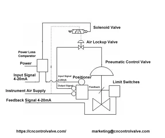
How we explain the real meaning of “fail position” to customers
When we review control valve specifications with customers, we always clarify one point early:
A fail position is not a mechanical guarantee.
It is an engineering assumption that must be validated on site.
In chemical plants, typical fail actions include:
- Fail Open (FO)
- Fail Close (FC)
- Fail Lock Open (FLO)
- Fail Lock Close (FLC)
These definitions describe what the valve should do when a failure occurs.
They do not describe what the valve will actually do unless the entire control chain behaves as expected.
This control chain includes:
- DCS analog output behavior
- Positioner power and configuration logic
- Pneumatic routing
- Actuator fail direction
If any part of this chain behaves differently, the fail position shown on drawings becomes meaningless.

A signal-loss accident we frequently help customers analyze
One typical case we have seen in chemical plants occurs during normal operation, not during startup.
What happened on site:
- The DCS output dropped below the minimum signal range required by the smart positioner
- The positioner lost power
- According to design, the valve should have failed closed
- In reality, the valve remained fully open
- The unit tripped immediately
What the plant team initially believed:
“Signal loss should automatically lead to fail action.”
What we found during engineering analysis:
- During commissioning, only loop checks and stroke calibration were performed
- Signal-loss behavior was never physically tested
- The positioner’s direct/reverse action had been modified to correct indication mismatch
- The impact of this change on fail behavior was never revalidated
The valve functioned perfectly — until it was required to fail safely.
Why loop checks and stroke tests do not reveal this risk
Many commissioning procedures focus on:
- Agreement between DCS output and valve position
- Linear response over the full stroke
- Stable behavior in auto mode
These tests confirm control accuracy, not failure behavior.
A signal-loss accident cannot be detected unless the test deliberately creates:
- Complete signal interruption
- Positioner power loss
- Independent air failure
If these conditions are not tested, fail behavior exists only as a theoretical assumption.

Smart positioners: accuracy improvement with hidden failure paths
Smart positioners significantly improve control performance, but they also introduce configuration risks.
In the field, we often see adjustments made to:
- Direct / reverse action
- Input signal range
- Internal logic parameters
These changes are usually made to solve indication or tuning issues.
However, they can silently alter how the valve behaves when power or signal is lost.
This explains why many fail-position accidents occur months after commissioning, not during initial startup.
How THINKTANK engineers troubleshoot signal-loss failures
When we support customers facing this issue, we do not immediately replace equipment.
We start by verifying failure logic, step by step.
First, we test true signal loss
- Forcing the AO below the positioner operating range
- Observing actual valve movement, not expected behavior
Second, we separate failure modes
- Signal loss
- Power loss
- Air loss
Each condition is tested independently.
Third, we review the complete control chain
- DCS AO action logic
- Positioner configuration
- Actuator fail direction
- Pneumatic connections
Only after this analysis do we decide whether hardware changes are required.

Engineering corrections we typically recommend
When THINKTANK engineers are involved in troubleshooting signal-loss accidents, our corrections focus on making failure behavior predictable, not simply restoring normal control.
Based on repeated field experience in chemical plants, we typically recommend the following engineering corrections.
First, fail-position behavior must be physically verified, not assumed.
Each control valve should be tested under true abnormal conditions, including:
- complete loss of control signal,
- loss of positioner power,
- and loss of instrument air.
Fail action should be confirmed by observing real valve movement on site, not inferred from configuration settings or drawings.
Second, the action logic across the control chain should be kept as simple and consistent as possible.
From our experience, unnecessary action reversals are a common source of signal-loss failures.
We generally recommend:
- configuring the DCS analog output (AO) as direct acting for air-to-open valves,
- configuring the DCS AO as reverse acting for air-to-close valves,
- keeping the field-mounted valve positioner in direct acting mode whenever possible,
- and performing any required logic inversion at higher system levels rather than inside the positioner.
This approach makes fail behavior easier to understand, easier to test, and less sensitive to configuration changes.
Third, any change to positioner configuration must trigger a mandatory fail-position retest.
Adjustments such as:
- direct/reverse action changes,
- signal range modification,
- or internal logic tuning
may not affect normal control, but they can fundamentally change valve behavior during signal or power loss.
These changes should never be accepted without re-verifying fail action.
Fourth, DCS output limits should be engineered deliberately.
Minimum AO values should be defined to avoid unintended positioner power loss, unless loss of signal is intentionally used as part of the safety logic.
Uncontrolled AO drop is a common and often overlooked cause of fail-position accidents.
Finally, fail-behavior verification should be treated as an acceptance requirement, not a commissioning formality.
We recommend documenting fail-position test results as part of the valve handover package, especially after maintenance, re-piping, or accessory replacement.
From our perspective, these corrections are not complex.
They simply enforce a basic engineering principle:
A control valve is only reliable when its failure behavior is fully understood, tested, and repeatable.
Our engineering conclusion
From the THINKTANK engineering perspective, control valve accidents rarely result from poor valve design.
They result from unverified assumptions hidden inside systems that appear to work perfectly.
A control valve is safe not because it controls well,
but because it fails exactly as engineers expect.