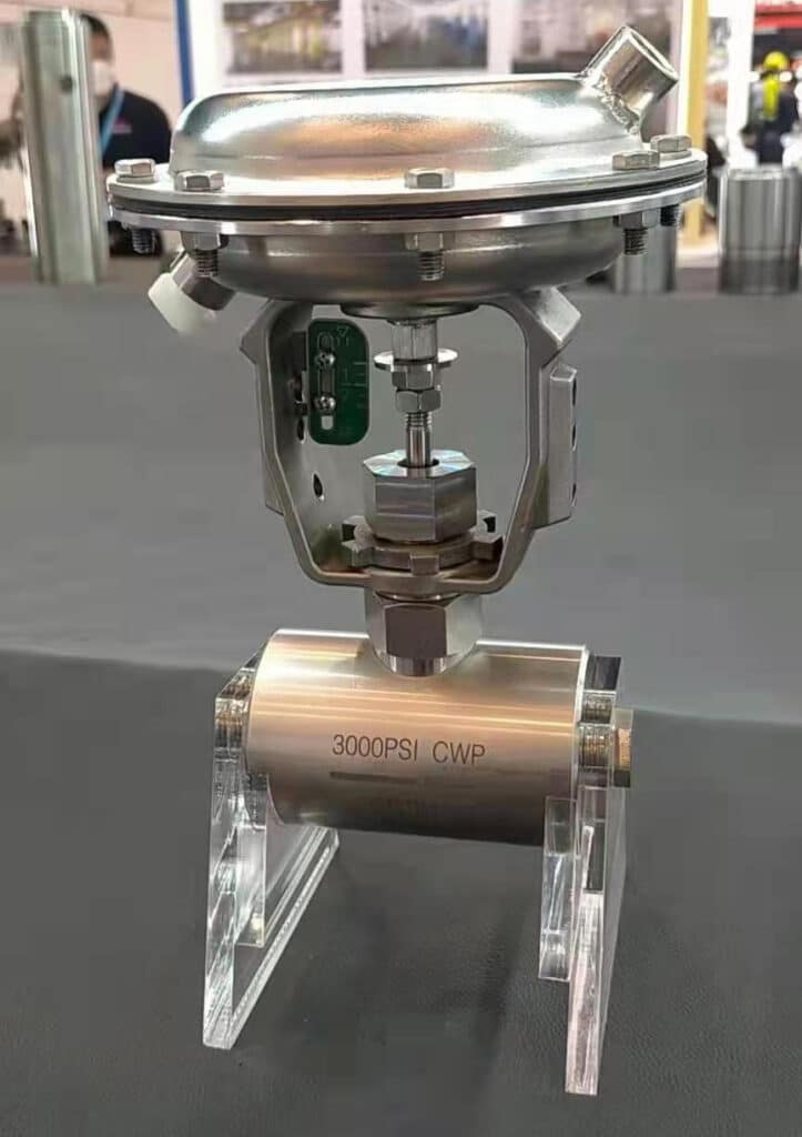
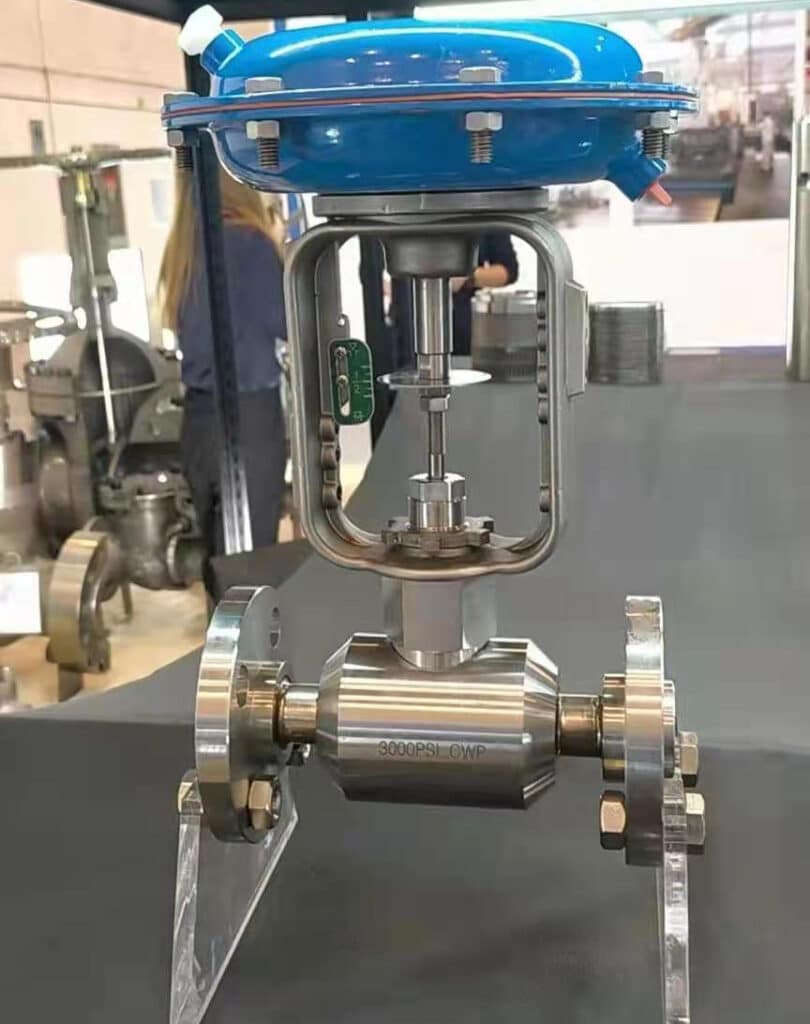
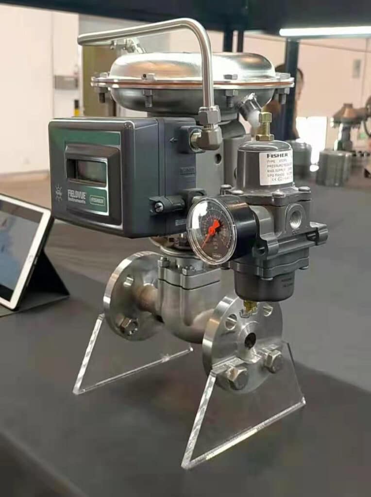
Regarding the provisions in the “Regulations on the Safe Operation of Air Separation Units”, the safe operation of oxygen valves should be emphasized, and safety precautions should be taken to avoid explosions due to excessive flow rate and other reasons. This article introduces the importance of coal chemical projects in the selection of oxygen control valve materials. Through the analysis of the flow rate of the oxygen medium, the safety measures for the selection of the material of the oxygen control valve body and valve trim, and solve the problem of the explosion caused by excessive flow velocity at the source and the requirements for the factory inspection of the oxygen control valve, to ensure all the materials of oxygen valves match the condition.
1. Analysis of the reasons for the excessively fast flow rate of the medium in the oxygen valves and pipeline.
One of the reasons that cause the device to explosion is excessively fast flow rate, and cause excessive flow rate has the following reasons.
1.1 Characteristics of oxygen
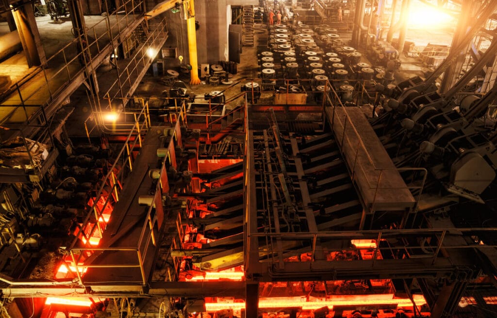
Oxygen itself cannot burn, but it is a very active combustion-supporting gas with chemical properties, which is a strong oxidant. Oxygen is combined with other substances to form oxides. The oxidation reaction is always going on. It is easy to explode when mixed with combustible gases such as hydrogen, acetylene, methane, coal gas, and natural gas in a certain proportion. The ability of its chemical reaction increases significantly with the increase of oxygen pressure and temperature. The higher the purity of oxygen, the higher the pressure makes greater the risk. When all kinds of grease come into contact with high-pressure oxygen, a fierce oxidation reaction will occur, which will burn or even explode quickly. So oxygen is not only a combustion-supporting gas but also can promote the spontaneous combustion of certain flammable substances.
1.2 Explosion of oxygen
a. Physical explosion.
There is no chemical reaction, and there is no significant increase in temperature. Generally, at normal temperature, the pressure vessel or pipeline bursts because the air pressure exceeds the yield limit and even the strength limit. If the oxygen cylinder has been used for a long time, the corrosion is serious, and the bottle wall becomes thin and has not been checked so that a physical overpressure explosion occurs during or after inflation.
b. Chemical explosion.
There is a chemical reaction, high temperature and high pressure, and instantaneous explosion. If hydrogen and oxygen are mixed in a bottle, it will explode when exposed to fire.
c. The explosion of oxygen.
Combustible materials, oxidants, and excitation energy must be present at the same time for the explosion. Both oxygen and liquid oxygen are strong oxidants. When combustibles are mixed with oxygen and there is an excitation energy source, combustion may occur, but it may not explode. Only when the oxygen and combustible gas are uniformly mixed and the volume fraction is within the explosion limit, the explosion can be triggered when it encounters the excitation energy. This is also the only difference between combustion conditions and explosion conditions.
1.3 Reasons for the explosion of the oxygen pipeline
There have been too many accidents of combustion and explosion in the oxygen pipeline, and most of them were when the control valves were opened. The oxygen pipeline is made of steel material, once the ferrite is on fire in the aerobic state, the temperature rises sharply, and the steel pipe will be burnt and melted. Analyzing the reason, it must be caused by sudden excitation energy, and there must be combustible substances such as grease in the valve. Excitation energy includes mechanical energy, such as impact, friction, adiabatic compression, etc.; thermal energy such as high-temperature gas, flame, etc.; electrical energy such as an electric spark, static electricity, etc.
The rust, dust, welding slag in the oxygen pipeline or the valve entrance friction generate high temperature and burn, which is related to the type, particle size, and gas flow rate of these impurities. Iron powder is easy to burn with oxygen, and the finer the particle size, the lower the ignition point, The faster the oxygen flow rate, the more likely it is to burn.
1.4 Reasons for the fire of the oxygen valves
The necessary condition for a combustion accident of the oxygen valve is the ignition source. If there is no ignition source, the oxygen valve will not burn. The flame in the ignition source is the direct cause of the fire and explosion of the oxygen pipeline. There are many reasons for a flame, such as a particle impact, adiabatic compression, friction, static electricity, etc. When the pipeline is installed, if there is not enough grounding, the airflow will rub against the pipe wall to generate static electricity. When the potential accumulates to a certain value, electric sparks may be generated, causing the oxygen in the pipeline to burn.
1.5 Potential dangers during operation of oxygen valve
When there are combustible substances with a low ignition point of 300-400°C in the oxygen pipeline, the low-ignition point substance can burn rapidly in oxygen and emit heat at a temperature of 800-900°C, which causes the oxygen valve to burn. The low ignition point combustible substances in oxygen pipelines are generally iron (Fe) and iron oxide (FeO) solid particles or powders, usually rust, welding slag, and other substances. When the valve is opened and closed quickly, the oxygen flow rate in the pipeline drives the solid particles to collide and friction with the valve inlet or the pipe wall. The shorter the valve opening and closing time, the greater the oxygen flow rate, the higher the heat generated by friction. At this time, oxygen produces adiabatic compression temperature rise, and theoretical calculation can reach a temperature rise of 300 to 500 ℃, and the low ignition point materials such as rust and welding slag in the pipeline will burn. Due to the rapid opening of the valve, the flow rate of oxygen at the outlet of the valve may reach the speed of sound, forming 6-7kV static electricity, and spark discharge will occur when the potential difference reaches 2kV or more.
In summary, the purity of oxygen produced by the coal chemical air separation unit is about 99.6%, the high oxygen delivery pressure in the pipeline, and the short valve opening and closing time are the main factors that produce the excessively fast oxygen flow rate.
2. The influence of oxygen flow speed on the selection of valve material
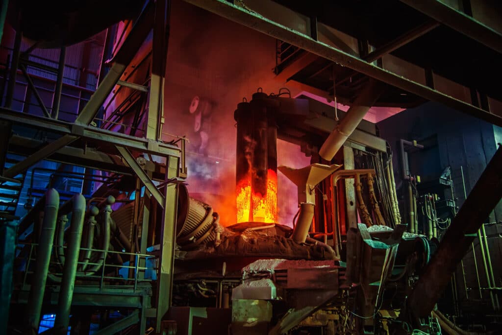
Controlling the maximum allowable flow rate in the oxygen pipeline is a crucial safety issue. The following takes the process parameters of the oxygen-carbon ratio control valve of a coal-water slurry gasification technology as an example to illustrate the material selection scheme of the high-pressure oxygen pipeline and the oxygen control valve under the design conditions.
Process parameter conditions: the outer diameter of the oxygen pipeline is 219mm, the inner diameter is 202mm, under normal operating conditions, the operating temperature is 33°C, the design temperature is 65°C, the inlet pressure of the valve is 8.48MPa G, and the design pressure is 9.90MPa G. The standard density is 1.43kg/m3, the operating density is 119kg/m3, the standard normal flow rate is about 4.16×10⁴m3/h, and the standard maximum flow rate is about 4.64×10⁴m3/h. After calculating, the normal flow speed and maximum flow speed of oxygen in the pipeline are 4.33m/s and 4.84m/s. According to the following sheet, we are selecting the material for the pipeline and the control valve.
2.1 China National standards on the flow speed of oxygen medium in the pipeline
Table 1 Maximum allowable flow speed in standard GB50030—2013 oxygen pipeline specification.
| Design Pressure p/MPa | Pipeline Material | Maximum Allowable Flow Speed v/(m•s-1) |
| 3.0 <p≤10.0 | Stainless Steel | 4.5 |
| 10.0<p≤20.0 | Stainless SteelCopper-Based Alloy | 4.56.0 |
In GB16912-2008 “Safety Technical Regulations for the Production of Oxygen and Related Gases by Deep Freezing Method”, the corresponding flow speed when the oxygen pipeline is made of different materials is also defined, as listed in Table 2.
Table 2 Definition of flow rate in GB16912—2008 oxygen pipeline
| Operating Pressure p/MPa | ||||||
| Material | P≤0.1 | 0.1<p≤1.0 | 1.0<p≤3.0 | 3.0<p≤10.0 | 10.0<p≤15.0 | p≥15.0 |
| Carbon Steel | Determined according to the pressure drop of the piping system | 20m/s | 15m/s | Not Allowable | Not Allowable | Not Allowable |
| Austenitic stainless steel | Determined according to the pressure drop of the piping system | 30m/s | 25m/s | pv≤45MPa•m/s(Impact occasion)pv≤80MPa•m/s(Non-Impact occasion) | 4.5m/s(Impact occasion)8.0m/s(Non-Impact occasion) | 4.5m/s |
Note:
- In the non-impact situation of stainless steel material, when p>10MPa, the flow speed is limited to 8.0M/s;
- The maximum allowable data refers to the actual flow speed at the lowest min. pressure and max. working temperature of the piping system;
- Copper and copper alloys (except aluminum-containing copper alloys), nickel and nickel-based alloys, under the condition of no more than 21.0MPa, the flow speed is not limited when the pressure drop is allowed.
The position where the fluid flow direction is suddenly changed or the vortex is generated, which causes the particles in the fluid to collide with the pipe wall. Such a position is called an impact occasion, otherwise, it is called a non-impact occasion.
For the definition of flow speed, refer to the European Industrial Gas Association (EIGA) Oxygen Pipeline Systems specification. It can be seen from Table 1 and Table 2 that when the oxygen pipeline pressure p is about 10 MPa and the flow speed exceeds 4.5 m/s, the pipeline material should preferably be made of nickel-based alloy Inconel or copper-based alloy Monel.
2.2 International standards on the material and flow speed of oxygen condition
When selecting the pipe material for the oxygen medium, there will be certain restrictions on the flow speed of oxygen according to the flammability of different metals. The alloy material can be flame retardant under the design pressure of the pipeline, so there is no need to consider the flow speed limit at this time. EIGA proposed an exempt pressure in the Oxygen Pipeline Systems specification, which means that the minimum pressure that can be exempted from considering the flow speed limit for the metal in the case of oxygen. During the 10 years from 2002 to 2012, the specification has made major revisions to the exempt pressure of copper-based alloy Monel material and nickel-based alloy Inconel material and the thickness of metal pipe walls.
In 2002, IGC Doc13/02/E Oxygen Pipeline Systems specified the exempt pressure and minimum thickness of metals of different materials, as listed in Table 3. In the 2012 IGCDoc13/12/E Oxygen Pipeline and Piping Systems upgrade specification, the exempt pressures of Inconel 600 and Inconel 625 are just the opposite, and the metal pipe wall thickness is also supplemented, as listed in Table 4.
Table 3 IGC Doc13/02/E metal exempt pressure and minimum thickness requirements.
| Alloy Steel Material | Min. Wall Thickness/mm | Exempt Pressure/MPa |
| Inconel 600 | Not Specified | 6.9 |
| Inconel 625 | 3.18 | 8.7 |
| Inconel 400 | Not Specified | 21 |
| Inconel 500 | Not Specified | 21 |
| 304/304L, 316/316L, 321, 347 | 3.18 | 1.4 |
| 304/304L, 316/316L, 321, 347 | 6.35 | 2.0 |
Table 4 IGC Doc13/12/E metal exempt pressure and minimum thickness requirements
| Alloy Steel Material | Min. Wall Thickness/mm | Exempt Pressure/MPa |
| Inconel 600 | 3.180 | 8.61 |
| Inconel 625 | 3.180 | 6.90 |
| Inconel 400 | 0.762 | 20.68 |
| Inconel 500 | 0.762 | 20.68 |
| 304/304L, 316/316L, 321, 347 | 3.180 | 1.38 |
| 304/304L, 316/316L, 321, 347 | 6.350 | 2.58 |
From Table 3 and Table 4, we know that when the exempt pressure of Monel400 and Monel500 is not greater than 20.68MPa, the oxygen flow speed is not limited when the pressure drop is allowed; while the exempt pressure of Inconel 600 is not greater than 8.61MPa and the exemption of Inconel 625 When the pressure is not more than 6.90MPa, the oxygen flow speed is not limited when the pressure drop is allowed.
2.3 Regulations for the selection of materials for oxygen control valves
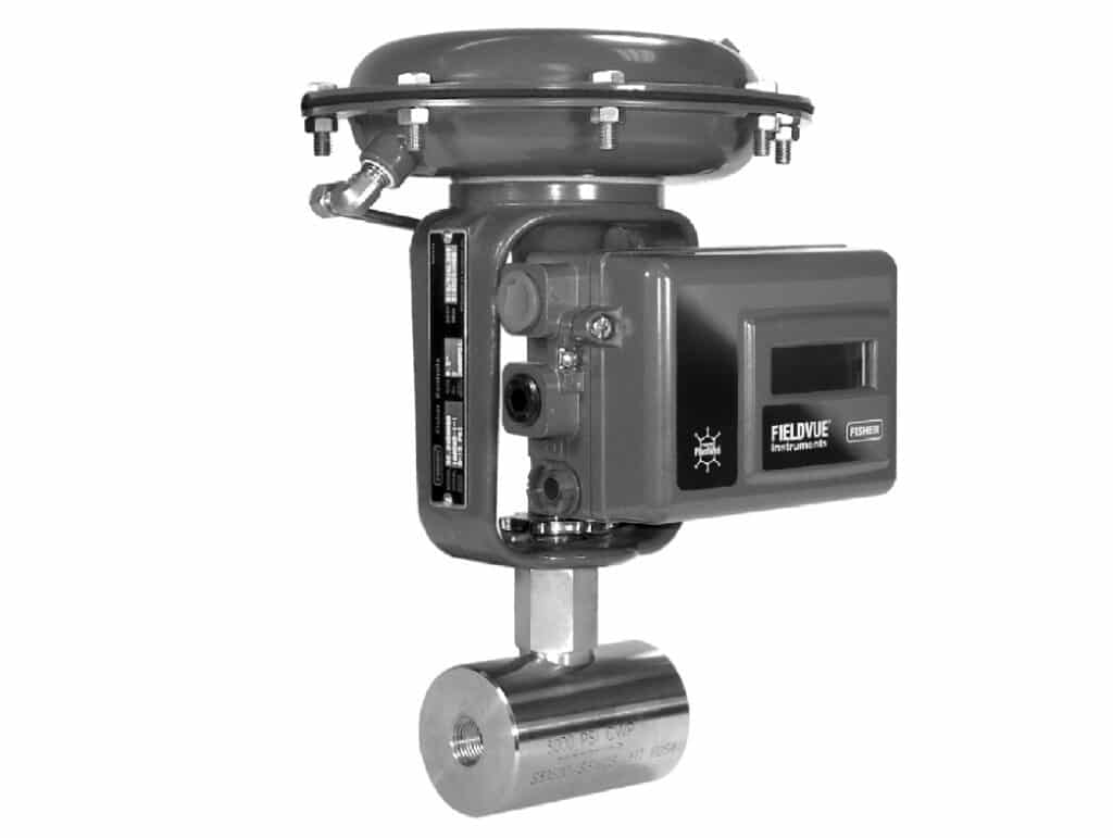
When the oxygen control valve is opened and closed, the oxygen flow direction suddenly changes, and a vortex is generated, which causes the particles entrained in the oxygen to impact the valve plug. Therefore, we must consider the valve plug material for impact flow speed. In standard GB16912-2008, different pressure corresponds to different valve material, see Table 5.
Table 5 GB16912—2008 Oxygen valve material selection
| Operating Pressure p/MPa | Material |
| p≤0.6 | Valve body, bonnet use forged steel, ductile iron, or cast steel. Stem use stainless steel. Plug use stainless steel. |
| 0.6<p≤10 | Use stainless steel, copper alloy steel or Monel steel, Inconel steel. |
| p>10 | Use copper-base steel, Ni, or Ni-base steel. |
Note:
- The material of the pressure or flow control valve whose working pressure is above 0.1MPa should be stainless steel or copper-based alloy or a combination of the above two material.
- The sealing and packing material of the valve should be made of polytetrafluoroethylene or flexible graphite material.
In summary, in the engineering design of coal water slurry gasification technology, according to the design conditions, if the design temperature of the oxygen medium is lower, the design pressure is higher, the flow speed is faster, etc., According to Table 1, Table 2, Table 4, oxygen pipeline material can select nickel-based alloy or copper-based alloy; According to Table 5, the oxygen control valve body can use nickel-based alloy or copper-based alloy, and the valve plug material can use nickel-based alloy Inconel 625 or copper-based alloy Monel 500, it means the body material and valve plug material are both flame-retardant alloys. At this time, there is no flow speed restriction when the oxygen medium collides with the valve plug. Even if there are entrained particles in the oxygen, there will be no sparks, and avoid Oxygen pressure and high flow rate of potential safety hazards.
3. Selection of forged valve body and casting valve body of oxygen control valve and manufacturing inspection requirements
3.1 The selection of forged valve body and casting valve body for oxygen control valve
In standard ASME B16.34-2013 Valves-flanged, Threaded, and Welding End, the material groups of copper-based alloy and nickel-based alloy for valve body:
a. Copper-based alloy material group 3.4, Forgings Spec. No. B564, Grade N04400, namely Monel 400, has no casting definition.
b. Nickel-based alloy material group Material Group3.8, Forgings Spec.No.B564, Grade N06625, namely Inconel 625, has no casting definition.
c. For N05500 copper-based alloy Monel 500, neither forging nor casting is defined in Group 3 Materials.
d. In clause 8.5.1 of the GB16912-2008 specification, when the oxygen valve material is under pressure p>10MPa, copper-based alloys, and nickel-based alloys are allowed use. but not specified material groups of copper-based alloys and nickel-based alloys.
According to standard ASME B16.34-2013 forged valve body and casting valve body material regulations, for copper-based alloy and nickel-based alloy materials, there are regulations for forging material grades, but there is almost no definition for casting material grades. German DIN standard has regulations for forging and casting of special alloy materials. Therefore, when copper-based alloy or nickel-based alloy material is required as the valve body material, a forged valve body is preferred.
3.2 Recommendations for manufacturing inspection requirements for oxygen valves
Because of the importance of oxygen control valves (especially high-pressure operating conditions), according to ASME B16.34-2013 and previous engineering experience, when purchasing oxygen control valves, we suggest referring to the following valve manufacturing inspection requirements:
a. Using forging material to process the valve body.
The flange and the valve body are should be forged as integrated. It is strictly forbidden to weld the flange with the body. Meanwhile, the forged valve body must be subjected to 100% ultrasonic (UT) inspection and 100% liquid penetration (PT) inspection. The inspection and acceptance comply with standard ASME B16.34-2013, and inspection reports were provided one by one.
b. Using casting material to process the valve body.
The flange and the valve body are should be cast as integrated, and the casting body shall be 100% radiographically inspected. The inspection method and quality assessment shall be by the standard ASME B16.34-2013. The inspection results should meet: pores (A) not less than level 2, sand inclusions (B) not less than level 2, shrinkage cavities (CA, CB, CC, CD) not less than level 2, non-hot cracks, and cold cracks (D, E), none inclusions and pitting (F, G), and inspection reports are provided one by one.
4. Recommendations for matching the material of the oxygen control valve body and plug
Generally, the temperature of the gaseous oxygen delivered from the air separation unit in the coal chemical industry to the coal gasification unit is close to normal temperature, and the control valve installed near the gasifier furnace head will cause the gasifier furnace head to be tempered in the event of a failure. The local high-temperature phenomenon of the oxygen pipeline, the design temperature is about 455℃. In this part, for the matching of the material of the oxygen control valve body and the valve core, the pressure that can withstand this temperature and the influence of the linear expansion coefficient of the selected material at high temperatures must be considered. The average linear expansion coefficients of copper-based alloy and nickel-based alloy materials at different temperatures are listed in Table 6.
Table 6 Average linear expansion coefficient of copper-based alloy and nickel-based alloy material 1/℃
| Temperature/℃ | Monel 500 | Monel 400 | Inconel 600 | Inconel 625 |
| 100 | 1.37 x 10⁻⁵ | 1.42 x 10⁻⁵ | 1.33 x 10⁻⁵ | 1.28 x 10⁻⁵(93℃) |
| 300 | 1.49 x 10⁻⁵ | 1.57 x 10⁻⁵ | 1.42 x 10⁻⁵ | 1.33 x 10⁻⁵(316℃) |
| 500 | 1.57 x 10⁻⁵ | 1.63 x 10⁻⁵ | 1.49 x 10⁻⁵ | 1.40 x 10⁻⁵(538℃) |
| 700 | 1.67 x 10⁻⁵ | 1.70 x 10⁻⁵ | 1.58 x 10⁻⁵ | 1.53 x 10⁻⁵(760℃) |
| 900 | – | 1.77 x 10⁻⁵ | 1.64 x 10⁻⁵ | 1.62 x 10⁻⁵(927℃) |
When the valve body and valve plug are selected from different groups of alloy materials, especially in high-temperature situations, we need to attention to the matching of the linear expansion coefficient of the material. According to the comparison of the linear expansion coefficients of copper-based alloys and nickel-based alloys in Table 6, the linear expansion coefficients of metals at 100°C and 500°C with vary greatly change. Therefore, for oxygen control valve work at the burner of the gasifier, we recommend using the linear expansion coefficient of the valve plug material that is smaller than the linear expansion coefficient of the valve body, to avoid the valve plug stuck with the valve body under high-temperature conditions.
Based on the above information and the rich engineering project experience, the selection of oxygen valve materials should first consider safety, then followed by strength and economy. The valve body material is recommended to be the same as the pipe material.
● According to Table 2 and Table 5, when p<10MPa or the flow rate is less than 4.5M/s, use 316SS valve body and Inconel 625 valve plug.
● According to Table 4-6, when p<6.90MPa, use Inconel 600 valve body and Inconel 625 valve plug; or use Monel 400 valve body and Inconel 625 valve plug; when p<8.61MPa, use Monel 400 valve body and Inconel 600 valve plug; when p<20.68MPa, use Monel 400 valve body and Monel 500 valve plug.
Stainless steel will not easy to rust, copper-based alloys and nickel-based alloys will not ignite when oxygen friction impacts, with good flame retardancy and high safety.
5. Attention in engineering design and application of oxygen valve
During the construction, operation, and maintenance of the oxygen control valve, the following aspects should be more careful:
a. The oxygen pipeline after construction and maintenance should be clean and free of debris before oxygen transfer, and the oxygen filter should be cleaned regularly.
b. After the oxygen pipeline is installed, overhauled, or put into use after a long-term shutdown, the remaining moisture, iron filings, and debris in the pipe should be purged with oil-free, dry air or blow off nitrogen until there is no iron filings, dust, and other impurities. The purge speed should not be less than 20m/s and the design flow speed of the oxygen pipeline. It is strictly forbidden to use oxygen to purge the pipeline.
c. Regularly check for leaks at the flange connection of the oxygen valve.
d. Oxygen pipelines and valves need to be free oil and degreasing treatment.
e. Production operators need to have regular safety training.
The following aspects should be paid attention to in the design of the oxygen control valve:
- It is strictly forbidden to use gate valves in the design of oxygen occasions.
- The oxygen control valve shall adopt metal to metal seat, and the valve leakage class shall be above ANSI V level.
- Valve body, stem, packing material, etc. can be implemented according to regulations.
- The oxygen control valve group should be equipped with an independent valve chamber or firewall, and the manual valve stem should be extended out of the firewall for operation. If the valve chamber firewall is not set separately, the pipes made of copper-based alloy Monel or nickel-based alloy Inconel should be used within the range of 8 times the nominal diameter of the regulating valve pipe before and after the oxygen control valve.
- For oxygen pressure p>1.0MPa and nominal diameter D≥150MM, pneumatic control valves should be used for the remote operation to avoid accidents.
Contact Us
If you have any inquiries about oxygen valves, please do not hesitate to contact sales representatives to serve you.
