Description
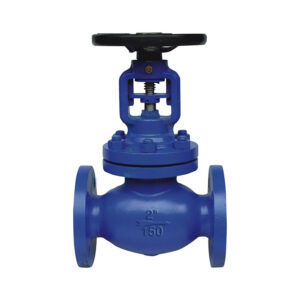
Brief of DIN Angle Globe Valve
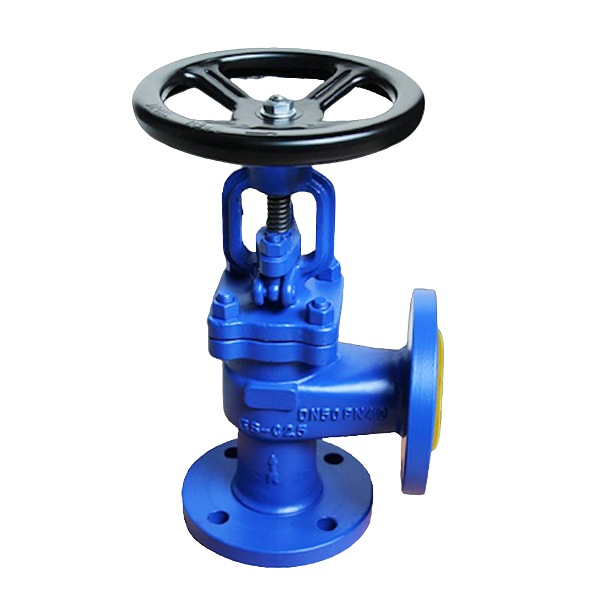
THINKTANK DIN Globe Valve is engineered to comply with the stringent DIN specifications, ensuring consistent quality and reliability. The innovative bellows design provides superior leak protection, extending the valve’s service life and reducing maintenance requirements.
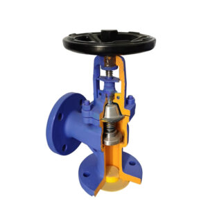
Key Features of DIN Angle Globe Valve
- Angle globe valve, its outlet is 90 degrees right angle, suitable for installation in the corner of the pipeline system, so as to save 90 degrees elbow, save material and space, and also easy to operate.
- The valve body adopts German film sand casting technology, which greatly improves the surface finish and mechanical properties of the valve body, reduces the appearance of porosity, sand holes and cracks, and enhances the tensile strength of the casting.
- When the valve is closed, the conical sealing surface with a “scraping effect” can automatically remove surface impurities, which can ensure the valve flap has a reliable seal and longer service life.
- Double sealing design (bellows + packing), in line with international sealing standards.
- 100% of all bellows pass the helium test and 100% of all valves pass the standard test to ensure zero leakage.
- For products above DN150, a special device (patented by our company) is added to effectively prevent the valve from trembling, making noise, and causing damage to the internal parts in use, effectively increasing the service life by more than 150%.
- We can provide various valve flap designs according to the requirements of working conditions, such as throttle type valve flap, stop check type valve flap, etc.
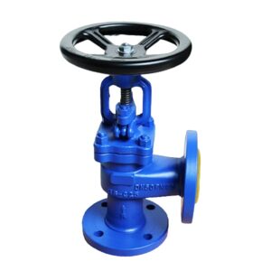
Advantage THINKTANK DIN Angle Globe Valve
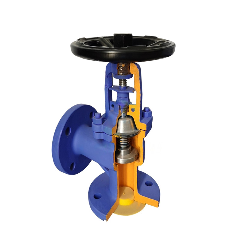
- The bellows component is a crucial element of below-sealed valves, which is securely attached to both the valve bonnet and valve stem through a sophisticated automatic roll welding process. This metal bellows construction ensures a 100% leak-free stem area.
- The double seal design incorporates both bellows and packing components. The metal bellows form a primary barrier to prevent leakage, while the packing serves as a secondary sealing mechanism in the event of bellows failure.
- The overlay welded seat guarantees reliable sealing performance, even in the most demanding conditions.
- The valve features an ergonomic handwheel, designed for enhanced durability and ease of operation.
Technical Specifications
- Design standard: DIN EN 13709:2002
- Face to face dimension: DIN EN 558-1:1995
- Flanged ends: DIN EN 1092-1:2002
- Welded ends: DIN EN 12627
- Test& inspection: DIN EN 12266:2003
Parts of DIN Angle Globe Valve
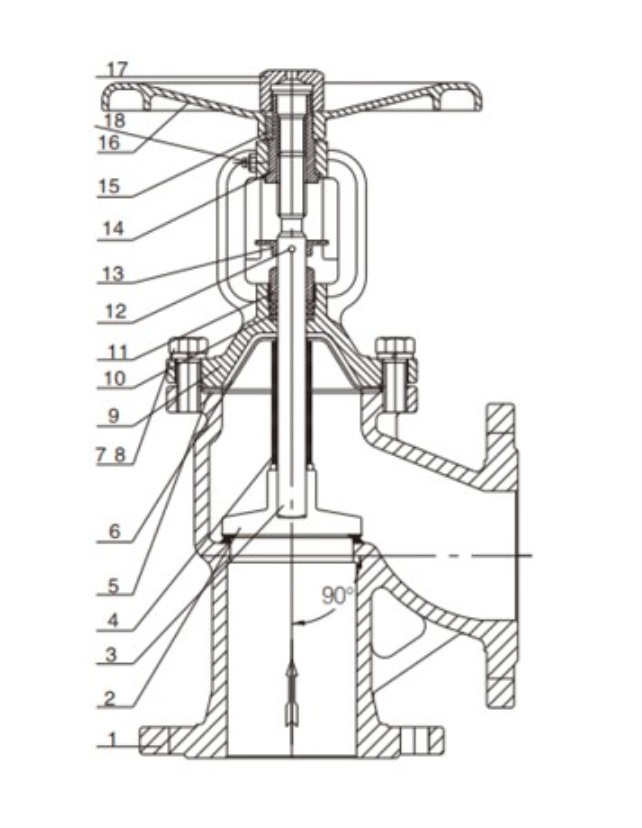
| No. | Parts Name | Materials | No. | Parts Name | Materials |
| 1 | Body | A216WCB | 10 | Packing | Flexible Graphite |
| 2 | Disc | 13Cr | 11 | Gland | A276 410 |
| 3 | Stem | SS410 | 12 | Pin | A276 410 |
| 4 | Bellows | SS304 | 13 | Spacer | SS410 |
| 5 | Gasket | FLEXIBLE GRAPHITE | 14 | Stem nut | BRONZE |
| 6 | Seal plate | SS304 | 15 | Key | 1045 |
| 7 | Spring shim | 1066 | 16 | Hand wheel | A572 |
| 8 | Bolt | A193B7 | 17 | Lack nut | 1045 |
| 9 | Bonnet | A216WCB | 18 | Lube fitting | BRASS |
DIN Angle Globe Valve Dimensions
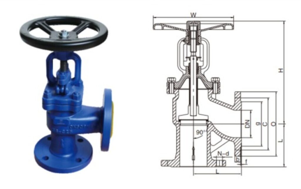
| PN16 | ||||||||||||||||
| Size DN | 15 | 20 | 25 | 32 | 40 | 50 | 65 | 80 | 100 | 125 | 150 | 200 | 250 | 300 | 350 | 400 |
| L RF/BW | 90 | 95 | 100 | 105 | 115 | 125 | 145 | 155 | 175 | 200 | 225 | 275 | 325 | 375 | 425 | 475 |
| D | 95 | 105 | 115 | 140 | 150 | 165 | 185 | 200 | 220 | 250 | 285 | 340 | 405 | 480 | 520 | 580 |
| w | 140 | 140 | 160 | 160 | 180 | 200 | 220 | 250 | 300 | 350 | 400 | 450 | 550 | 600 | 700 | 700 |
| H | 200 | 200 | 212 | 212 | 248 | 248 | 287 | 320 | 390 | 412 | 470 | 630 | 740 | 840 | 990 | 1100 |
| Weight{kg) | 3.8 | 4.8 | 5.7 | 7.6 | 9 | 12 | 16 | 22 | 33 | 45 | 70 | 135 | 260 | 305 | 510 | 740 |
| Stroke | 8 | 8 | 10 | 10 | 12 | 15 | 17 | 22 | 28 | 34 | 40 | 60 | 75 | 85 | 100 | 110 |
| Kvs(m3/h) | 4.2 | 7.4 | 12 | 19 | 30 | 47 | 77 | 120 | 188 | 285 | 410 | 725 | 1140 | 1660 | 2230 | 2950 |
| PN25 | ||||||||||||||||
| Size DN | 15 | 20 | 25 | 32 | 40 | 50 | 65 | 80 | 100 | 125 | 150 | 200 | 250 | 300 | 350 | 400 |
| L RF/BW | 90 | 95 | 100 | 105 | 115 | 125 | 145 | 155 | 175 | 200 | 225 | 275 | 325 | 375 | 425 | 475 |
| D | 95 | 105 | 115 | 140 | 150 | 165 | 185 | 200 | 235 | 270 | 300 | 360 | 425 | 485 | 555 | 620 |
| w | 140 | 140 | 160 | 160 | 180 | 200 | 220 | 250 | 300 | 350 | 400 | 450 | 550 | 600 | 700 | 700 |
| H | 200 | 200 | 212 | 212 | 248 | 248 | 287 | 320 | 390 | 412 | 470 | 630 | 740 | 840 | 990 | 1100 |
| Weight{kg) | 3.8 | 4.8 | 5.7 | 7.6 | 9 | 12 | 16 | 22 | 34 | 46 | 72 | 138 | 270 | 310 | 520 | 760 |
| Stroke | 8 | 8 | 10 | 10 | 12 | 15 | 17 | 22 | 28 | 34 | 40 | 60 | 75 | 85 | 100 | 110 |
| Kvs(m3/h) | 4.2 | 7.4 | 12 | 19 | 30 | 47 | 77 | 120 | 188 | 285 | 410 | 725 | 1140 | 1660 | 2230 | 2950 |
| PN40 | ||||||||||||||||
| Size DN | 15 | 20 | 25 | 32 | 40 | 50 | 65 | 80 | 100 | 125 | 150 | 200 | 250 | 300 | 350 | 400 |
| L RF/BW | 90 | 95 | 100 | 105 | 115 | 125 | 145 | 155 | 175 | 200 | 225 | 275 | 325 | 375 | 425 | 475 |
| D | 95 | 105 | 115 | 140 | 150 | 165 | 185 | 200 | 235 | 270 | 300 | 375 | 450 | 515 | 580 | 660 |
| w | 140 | 140 | 160 | 160 | 180 | 200 | 220 | 250 | 300 | 350 | 400 | 450 | 550 | 600 | 700 | 700 |
| H | 200 | 200 | 212 | 212 | 248 | 248 | 287 | 320 | 390 | 412 | 470 | 630 | 740 | 840 | 990 | 1100 |
| Weight{kg) | 3.8 | 4.8 | 5.7 | 7.6 | 9 | 12 | 16 | 22 | 35 | 48 | 75 | 140 | 275 | 315 | 530 | 770 |
| Stroke | 8 | 8 | 10 | 10 | 12 | 15 | 17 | 22 | 28 | 34 | 40 | 60 | 75 | 85 | 100 | 110 |
| Kvs(m3/h) | 4.2 | 7.4 | 12 | 19 | 30 | 47 | 77 | 120 | 188 | 285 | 410 | 725 | 1140 | 1660 | 2230 | 2950 |
Available Disc Types
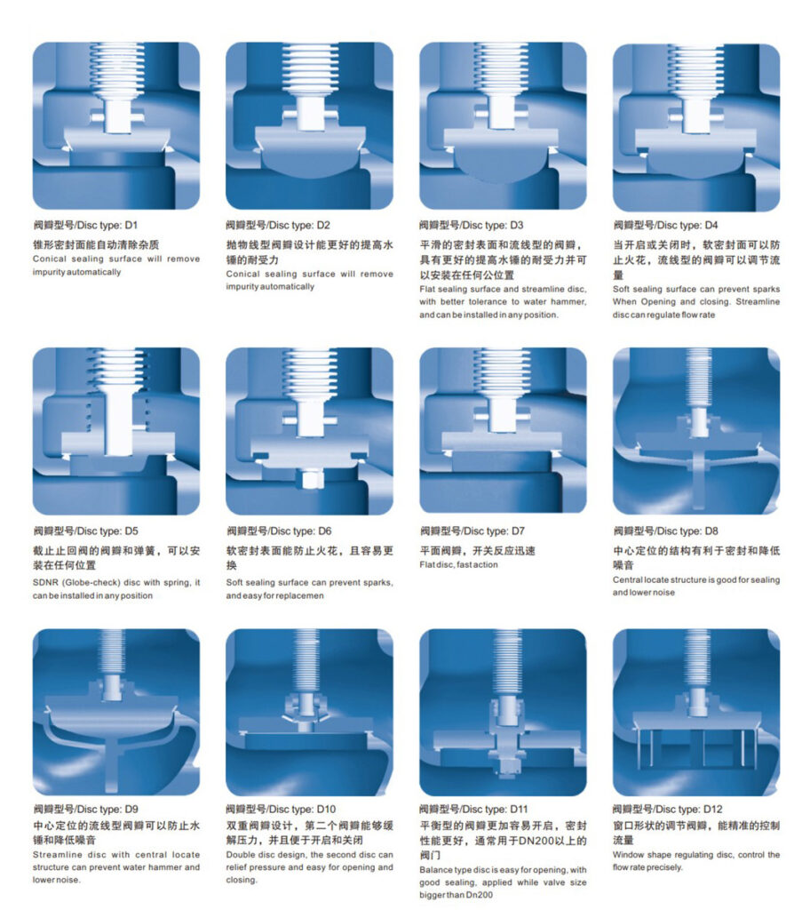
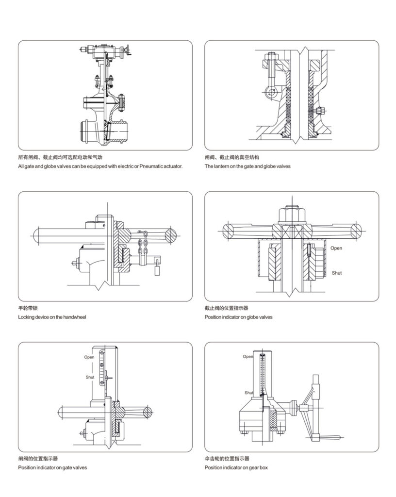
Special Design On Handwheel
