Product Overview
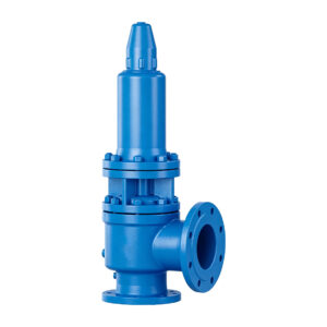
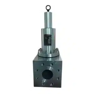
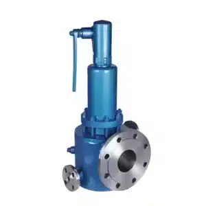
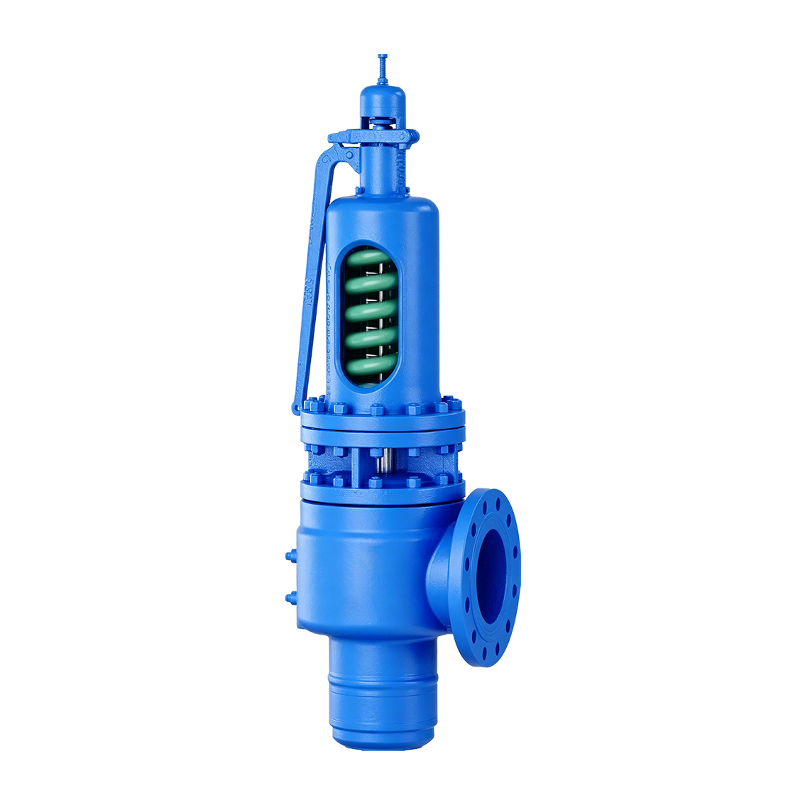
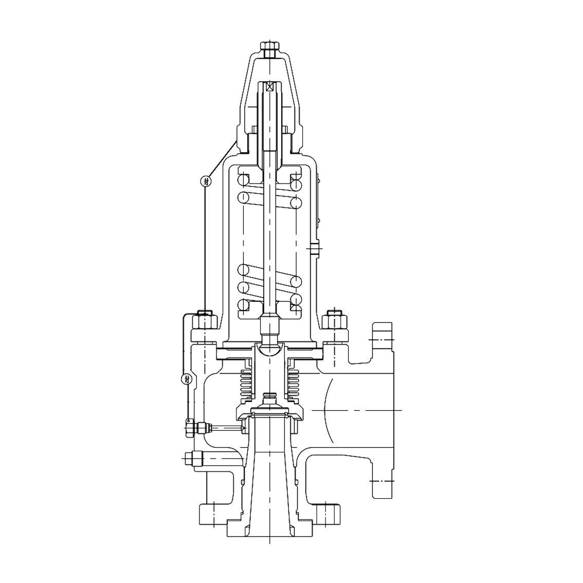
The THINKTANK ASME Safety Relief Valve Series is a spring-loaded pressure relief valve platform designed for overpressure protection of pressure vessels, process equipment and piping systems.
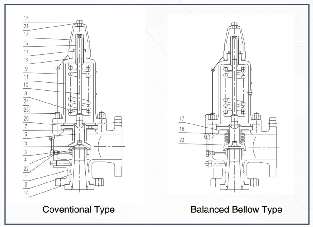
The product family is available in both conventional spring-loaded and balanced bellows configurations, with multiple seat, bonnet and lifting-device arrangements to suit different gas and liquid applications.
The valve design incorporates an adjustable blowdown arrangement, precision-guided moving components and hardened sealing surfaces to provide stable operation, repeatable performance and reliable seat tightness.
Balanced bellows configurations are available for applications where back pressure may influence the operation of a conventional spring-loaded safety valve.
Applicable Standards
The supplied product specification identifies the following applicable standards and codes:
- ISO 4126-1 — Safety valves
- API RP 520 — Sizing, selection and installation of pressure-relieving devices
- API Std 526 — Steel flanged pressure relief valves
- API Std 527 — Seat tightness of pressure relief valves
- ASME Boiler and Pressure Vessel Code, Section VIII, Division 1 — Rules for construction of pressure vessels
The applicable code, edition, project specification and certification requirements should be confirmed for each order.
Performance
| Performance Item | Requirement |
|---|---|
| Set Pressure Tolerance | ≤ ±3% |
| Overpressure – Gas Service | ≤10% |
| Overpressure – Liquid Service | ≤20% |
| Blowdown – Gas Service | ≤10% |
| Blowdown – Liquid Service | ≤20% |
| Seat Tightness | In accordance with API Std 527 |
Final acceptance criteria should be confirmed according to the selected valve configuration, applicable standard and project specification.
Conventional and Balanced Bellows Designs
The safety relief valve platform is available in two principal configurations.
Conventional Type
The conventional spring-loaded design is suitable where discharge-side back pressure is within the allowable range for a standard direct spring-loaded safety valve.
Balanced Bellows Type
The balanced bellows configuration incorporates a bellows assembly around the spindle and pressure-sensitive components.
The bellows is designed to reduce the influence of back-pressure fluctuations on valve operating performance while also providing additional separation between the process medium and upper bonnet components.
Balanced bellows construction should be considered where:
- Variable back pressure exists
- The valve discharges into a closed relief system
- Several relief devices share a common discharge header
- The process medium is corrosive
- Additional protection of spring and bonnet internals is required
Actual allowable back pressure should be verified during final valve sizing.
Full-Lift Operating Design
The valve incorporates an umbrella-type reaction disc arrangement designed to increase lifting force after initial opening.
This allows the disc to move rapidly toward its relieving position at relatively low overpressure, providing timely discharge of the process medium.
An adjusting ring is provided for control of the valve blowdown or reseating pressure differential.
The actual lift, certified capacity and overpressure requirements should be confirmed for the selected valve size and configuration.
Seat and Trim Configurations
Different seat arrangements are available depending on service requirements.
Available configurations shown in the product design include:
- Conventional metal-seat arrangement
- Resilient seat with O-ring
- Resilient seat with padded sealing element
- Liquid-service trim configuration
Resilient-seat arrangements can be considered where improved tightness below set pressure is required, subject to compatibility between the resilient material, process medium, pressure and temperature.
Cooling Chamber Design
A cooling chamber configuration is available for specific operating conditions.
The cooling section provides additional thermal separation between the process-containing portion of the valve and temperature-sensitive upper components.
The requirement for a cooling chamber should be evaluated according to the actual process and relieving temperatures.
Bonnet and Lifting Arrangements
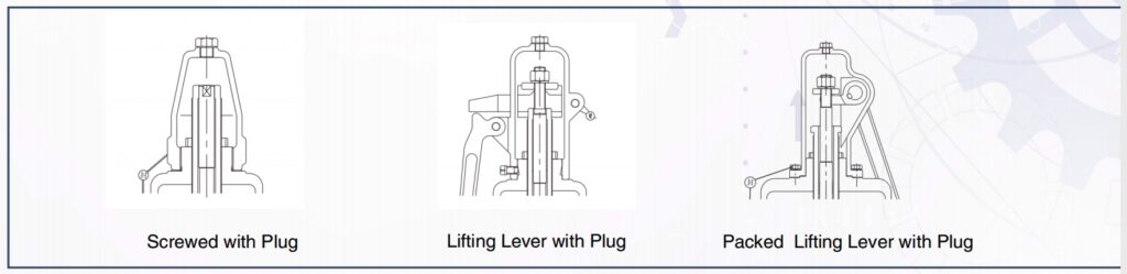
The product platform supports several bonnet and lifting-device configurations, including:
- Screwed configuration with plug
- Lifting lever with plug
- Packed lifting lever with plug
The appropriate arrangement should be selected according to the process medium, leakage-control requirements, operating procedure and applicable project specification.
Nozzle and Body Construction
The nozzle and valve body use a separable construction.
This arrangement can simplify inspection, servicing and replacement of pressure-containing or sealing components compared with a fully integral construction.
Precision clearances are applied to the reaction disc, guide sleeve, stem and related moving components to support smooth and stable valve movement.
Sealing Surface Design
The sealing surfaces of the disc and nozzle are hardfaced with wear-resistant alloy and precision machined.
This construction is intended to improve resistance to:
- Seat wear
- Erosion during relieving
- Repeated opening and closing
- Mechanical damage to sealing surfaces
The actual hardfacing material should be confirmed according to the selected trim configuration.
Material Configurations
The supplied material sheet identifies C, CS, C6, C9, CM, CC, CB and L material configurations.
Because the source data does not define the service designation represented by each code, the combinations are reproduced without assigning additional application meanings.
| Ref. No. | Part Name | C | CS | C6 | C9 | CM | CC | CB | L |
|---|---|---|---|---|---|---|---|---|---|
| 1 | Body | WCB | WCB | WC6 | WC9 | WCB | WCB | WCB | LCB |
| 2 | Nozzle | 304 | 316 | 316 | 316 | Monel | H.C. | H.B. | 304 |
| 3 | Nozzle Ring | CF8M | CF8M | CF8M | CF8M | CF8M | CF8M | CF8M | CF8M |
| 4 | Set Screw | 304 | 304 | 304 | 304 | 304 | 304 | 304 | 304 |
| 5 | Disc | 304 | 316 | 316 | 316 | Monel | H.C. | H.B. | 304 |
| 6 | Disc Holder | 420 | 420 | 420 | 420 | 630 | 630 | 630 | 420 |
| 7 | Guide | 304 | 304 | 304 | 304 | 304 | 304 | 304 | 304 |
| 8 | Spring Washer | Carbon Steel | Carbon Steel | Carbon Steel | Carbon Steel | 420 | 420 | 420 | Carbon Steel |
| 9 | Spring | Alloy Steel | Alloy Steel | Alloy Steel | Alloy Steel | Stainless Steel / Alloy Steel | Stainless Steel / Alloy Steel | Stainless Steel / Alloy Steel | Alloy Steel |
| 10 | Spindle | 420 | 420 | 420 | 420 | 420 | 420 | 420 | 420 |
| 11 | Bonnet | WCB | WCB | WCB | WCB | WCB | WCB | WCB | WCB |
| 12 | Adjusting Bolt | 420 | 420 | 420 | 420 | 420 | 420 | 420 | 420 |
| 13 | Cap | WCB | WCB | WCB | WCB | WCB | WCB | WCB | WCB |
| 14 | Adjusting Bolt Nut | Carbon Steel | Carbon Steel | Carbon Steel | Carbon Steel | Carbon Steel | Carbon Steel | Carbon Steel | Carbon Steel |
| 15 | Plug | Carbon Steel | Carbon Steel | 304 | 304 | Carbon Steel | Carbon Steel | Carbon Steel | 304 |
| 16 | Bellows | 316L | 316L | 316L | 316L | 316L | 316L | 316L | 316L |
| 17–23 | Gaskets | Non-Asbestos | Non-Asbestos | Non-Asbestos | Non-Asbestos | Non-Asbestos | Non-Asbestos | Non-Asbestos | Non-Asbestos |
| 24 | Bolt | A193-B7 | A193-B7 | A193-B7 | A193-B7 | A193-B7 | A193-B7 | A193-B7 | A193-B8 |
| 25 | Nut | A194-2H | A194-2H | A194-7 | A194-7 | A194-2H | A194-2H | A194-2H | A194-8 |
Notes:
- H.C. and H.B. are retained exactly as specified in the supplied material sheet.
- Actual bill of materials depends on the selected conventional or balanced bellows configuration.
- Final material selection should be confirmed according to medium, pressure, temperature, corrosion conditions and project specification.
Storage
Safety relief valves may remain at the project site for an extended period before installation.
To prevent contamination or deterioration prior to commissioning:
- Keep the valve in its original shipping packaging until installation
- Store the valve in a clean and dry environment
- Protect the valve inlet, outlet and internal components from dirt, moisture and foreign material
Improper storage may adversely affect valve performance and seat tightness.
Installation
Before installation, the connected piping, valve inlet and pressure-containing system should be thoroughly cleaned.
Foreign material such as:
- Welding slag
- Scale
- Dirt
- Metal particles
- Construction debris
should be removed before commissioning.
Contamination entering the nozzle or seat can affect safety valve tightness and operating performance.
Inlet Piping
The inlet piping internal diameter should be equal to or larger than the safety valve inlet diameter.
A safety valve should not be installed on inlet piping having an internal diameter smaller than the valve inlet connection.
The inlet piping should also be kept as short as practical.
The valve should be installed vertically on the inlet nozzle unless the approved valve design and project specification state otherwise.
Flange bolts and stud bolts should be tightened evenly to avoid excessive piping stress, flange deformation or internal misalignment.
Outlet Piping
Discharge piping should be kept as short and straight as practical and should have a diameter at least equal to the valve outlet size.
The discharge system should be arranged to minimize external loads acting on the safety valve, including:
- Reaction forces during relieving
- Discharge piping weight
- Vibration loads
- Static loads caused by piping misalignment
Discharge piping support should be designed independently so that excessive piping loads are not transferred into the valve body.
Safety Relief Valve Selection
For correct selection of the ASME Safety Relief Valve Series, provide:
- Process medium
- Gas, vapor or liquid service
- Set pressure
- Normal operating pressure
- Design pressure
- Operating temperature
- Relieving temperature
- Required relieving capacity
- Superimposed back pressure
- Built-up back pressure
- Required inlet and outlet sizes
- Required pressure class
- Conventional or balanced bellows design
- Metal or resilient seat requirement
- Bonnet / lifting lever arrangement
- Required materials
- Applicable ASME/API/ISO requirements
- Certification or stamping requirements
- Installation and discharge-header arrangement
For balanced bellows applications, maximum back pressure and discharge-header conditions should be clearly identified.
Engineering Support
THINKTANK supports EPC contractors, pressure vessel manufacturers, oil & gas companies, chemical plants, power companies, system integrators and industrial equipment manufacturers with:
- Safety relief valve sizing and selection
- Conventional vs. balanced bellows selection
- Relieving capacity calculation
- Back-pressure evaluation
- Set-pressure and blowdown configuration
- Material selection
- Resilient-seat selection
- Installation and discharge-piping review
- Dimensional drawings
- 3D models for system integration
- Existing safety valve replacement evaluation
- Project-specific technical documentation
With more than 30 years of industrial valve application experience, THINKTANK can support safety relief valve selection and equivalent replacement for demanding international projects.