Product Overview
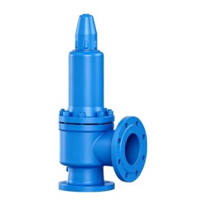
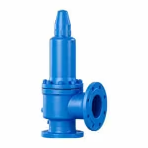
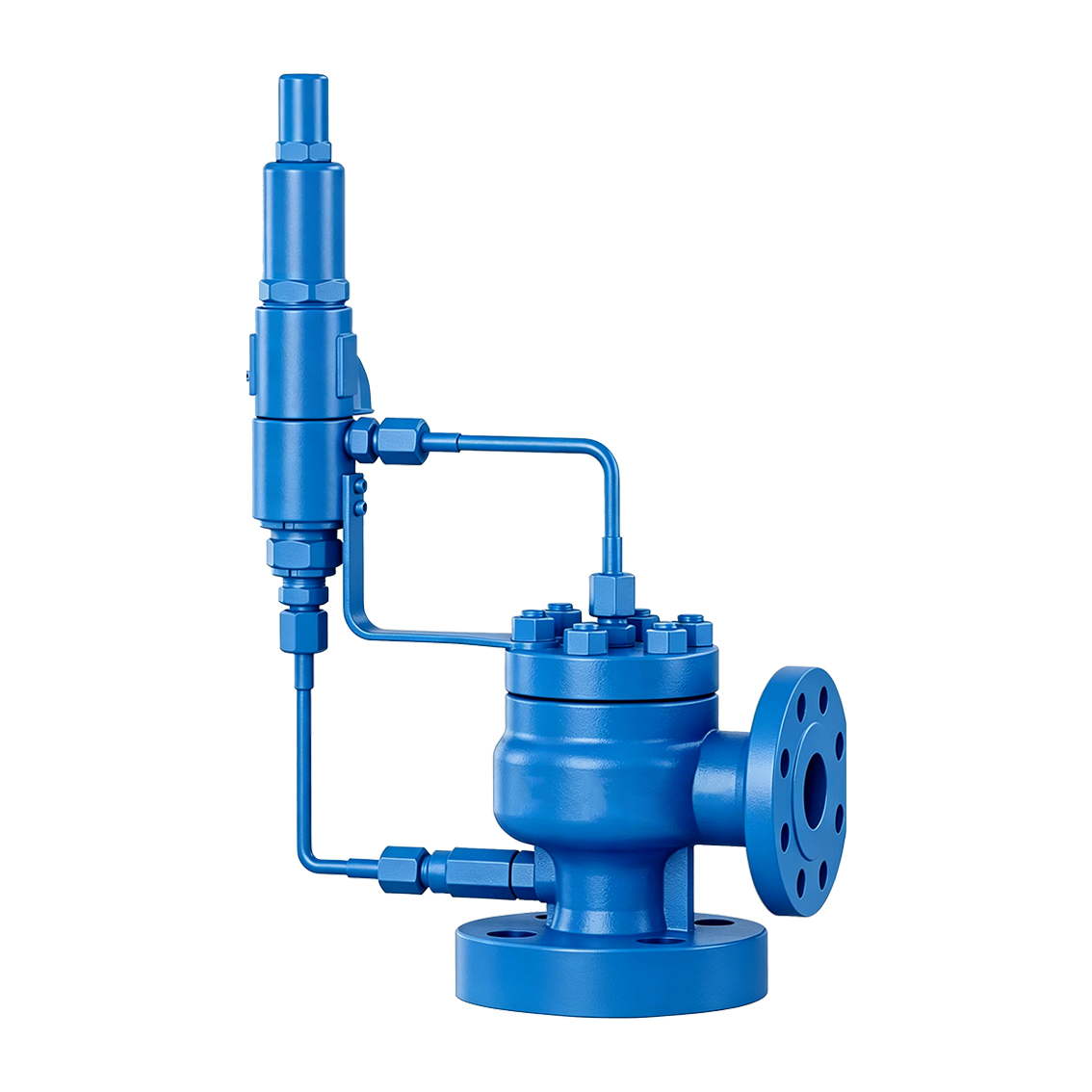
The THINKTANK TT-A46Y/F Series is a pilot-operated safety relief valve designed for overpressure protection of pressurized equipment, vessels and piping systems.
Unlike a conventional direct spring-loaded safety valve, the spring acts directly on the pilot valve, while the pilot system controls pressure acting on the main valve piston.
This indirect operating principle allows the main valve to remain tightly closed during normal operation while providing rapid opening when the specified set pressure is reached.
The TT-A46Y/F is suitable for industrial applications including oil and natural gas, chemical processing, power generation, metallurgy, municipal gas systems and other pressurized process installations.
Quick Specifications
| Parameter | Specification |
|---|---|
| Model | TT-A46Y/F |
| Product Type | Pilot-Operated Safety Relief Valve |
| Main Valve Design | Sleeve-Guided Piston |
| Pilot Type | Pop Pilot |
| Pilot Arrangement | Guided, Non-Flowing |
| Seat Type | Soft Seat |
| Size Range | DN25–DN200 depending on pressure rating |
| Pressure Rating | PN16 / PN25 / PN40 / PN64 / PN100 / PN160 |
| Set Pressure Tolerance | Within ±3% |
| Overpressure | ≤10% |
| Blowdown | ≤10% |
| Seat Tightness | API Std 527 |
| Manufacturer | THINKTANK |
How It Works
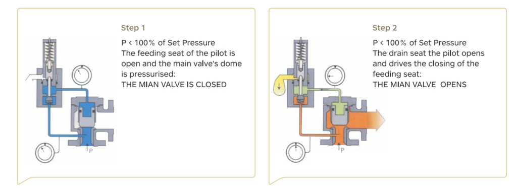
The TT-A46Y/F uses a pilot-operated pressure control system to actuate the main relief valve.
During normal operation, system pressure is transmitted through the pilot tubing to the control chamber of the main valve.
The pressure acting on the main piston, together with the effective sealing arrangement, keeps the main valve tightly closed.
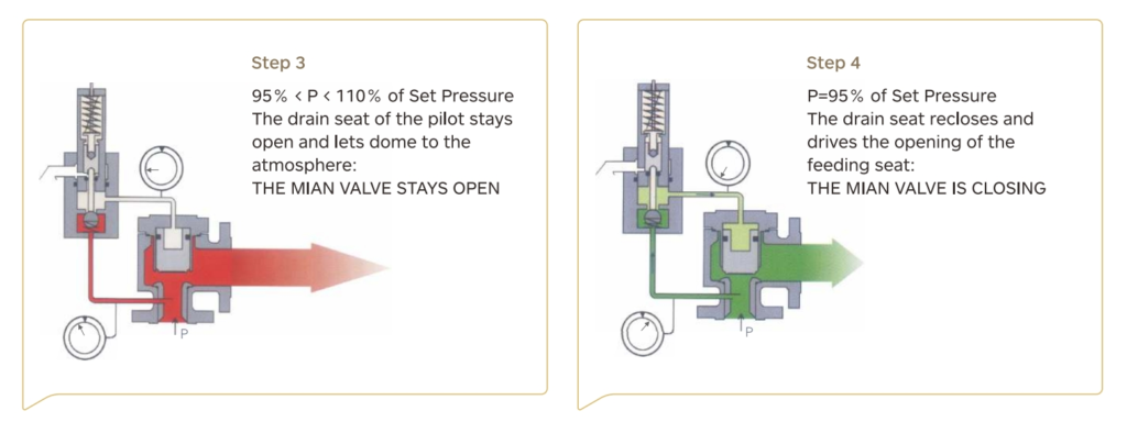
When system pressure reaches the specified set pressure, the pilot valve operates and changes the pressure condition acting on the main valve control chamber.
This pressure change allows the main piston to move rapidly and opens the main valve for pressure relief.
After system pressure decreases to the required reseating level, the pilot resets, pressure is restored to the main valve control chamber and the main valve recloses.
Pilot and Main Valve Construction
The TT-A46Y/F consists of a main relief valve connected to a separate pilot through external tubing.
The major functional components shown in the product construction include:
- Pop pilot
- Pilot tubing
- Filter
- Main valve body
- Nozzle
- Disc
- Guide
- Spring
- Bonnet
- Seal rings
The main valve uses a sleeve-guided piston design, providing controlled piston movement and repeatable opening and closing behavior.
Operation Close to Set Pressure
One of the principal advantages of the pilot-operated design is the ability to maintain stable valve closure while the normal operating pressure approaches the safety valve set pressure.
The pilot-controlled main valve maintains closing force independently of a conventional main spring acting directly on the disc.
This allows the system to operate with a smaller pressure margin between normal operating pressure and set pressure than may be practical with some conventional spring-loaded safety valve arrangements.
The actual allowable operating-to-set-pressure ratio should be confirmed for the selected valve configuration and project conditions.
Soft-Seat Tightness
The TT-A46Y/F incorporates soft-seat sealing to provide high seat tightness during normal operation.
This is particularly useful where:
- Process fluid loss must be minimized
- Fugitive release is undesirable
- Operating pressure is close to set pressure
- Repeated opening and reclosing may occur
- Tight shutoff after valve operation is important
The listed seat tightness requirement is in accordance with API Std 527.
Back-Pressure Capability
The pilot-operated construction is designed to reduce the influence of discharge-side back pressure on main valve operating performance and lift.
This makes the TT-A46Y/F suitable for applications involving:
- Closed relief systems
- Pressurized discharge headers
- Common relief manifolds
- Variable back pressure
- High discharge-side pressure
Actual allowable back pressure should be checked against the selected pilot and main valve configuration during final sizing.
Rapid Full-Lift Opening
The pilot-operated mechanism requires only a relatively small overpressure to actuate the main valve rapidly.
According to the listed performance data:
Overpressure: ≤10%
Once the pilot actuates, the pressure condition in the main valve control chamber changes rapidly, allowing the main valve to reach its relieving position quickly.
This provides a fast response to system overpressure conditions.
Adjustable Blowdown
The TT-A46Y/F provides an adjustable blowdown function.
Listed blowdown: ≤10%
Blowdown is the pressure difference between the valve opening pressure and the pressure at which the valve reseats after relieving.
Adjustment allows the valve operating cycle to be matched more closely to the requirements of the protected system.
Non-Flowing Pilot Design
The pilot system uses a guided, non-flowing design.
During normal operation, this arrangement minimizes continuous process-fluid discharge through the pilot circuit.
This feature can be beneficial for applications involving:
- Hazardous media
- Flammable gases
- Toxic process fluids
- Valuable process gases
- Applications where environmental release should be minimized
Set Pressure Monitoring and Calibration
The TT-A46Y/F configuration supports checking and adjustment of the pilot set pressure without requiring direct adjustment of the main valve spring.
Depending on the project test arrangement, this can simplify:
- Set-pressure verification
- Pilot adjustment
- Calibration
- Maintenance inspection
The required online test or monitoring arrangement should be specified during project engineering.
Pilot Valve Performance
| Performance Item | Requirement |
| Set Pressure Tolerance | Within ±3% |
| Overpressure | ≤10% |
| Blowdown | ≤10% |
| Seat Tightness | In accordance with API Std 527 |
These performance values are based on the supplied TT-A46Y/F product data. Final project acceptance criteria should be confirmed according to the applicable specification and selected valve configuration.
General Performance Requirements
| Applicable Medium | Shell Test Pressure Ps | Seal Test Pressure Pm | Blowdown ΔP | Discharge Pressure Pp | Lift Height H |
| Steam | — | 90% Pk or the minimum reseating pressure, whichever is lower | When Pk ≤ 0.4 MPa: ΔP ≤ 0.04 MPa; when Pk > 0.4 MPa: ΔP ≤ 10% Pk | ≤1.03 Pk | Full-lift: ≥1/4 d₀; Low-lift: ≥1/20 d₀ |
| Air or other gases | 1.5 PN | When Pk ≤ 0.3 MPa: Pm = Pk − 0.03 MPa; when Pk > 0.3 MPa: Pm = 90% Pk | When Pk ≤ 0.2 MPa: ΔP ≤ 0.03 MPa; when Pk > 0.2 MPa: ΔP ≤15% Pk | ≤1.1 Pk | Full-lift: ≥1/4 d₀; Low-lift: ≥1/20 d₀ |
| Water or other liquids | — | When Pk ≤ 0.3 MPa: Pm = Pk − 0.06 MPa; when Pk > 0.3 MPa: Pm = 80% Pk | When Pk ≤ 0.3 MPa: ΔP ≤0.06 MPa; when Pk > 0.3 MPa: ΔP ≤20% Pk | ≤1.2 Pk | Full-lift: ≥1/4 d₀; Low-lift: ≥1/20 d₀ |
Notes:
- Pk = Set pressure
- d₀ = Orifice diameter
- PN = Nominal pressure
- The TT-A46Y/F has its own pilot-operated performance requirements listed above; final acceptance criteria should be based on the actual valve configuration and project specification.
Material Configurations
The supplied product data lists six material configuration codes: C, P, R, RL, L and CM.
Because the original data does not define the naming logic behind these configuration codes, the material combinations are reproduced below without assigning additional service definitions.
| No. | Part Name | C | P | R | RL | L | CM |
| 1 | Nozzle | 304 | 304 | 316 | 316L | 304 | MONEL |
| 2 | Disc Assembly | 304 + F46 | 304 + F46 | 316 + F46 | 316L + F46 | 304 + F46 | MONEL + F46 |
| 3 | Guide | 304 | 304 | 316 | 316L | 304 | MONEL |
| 4 | Body | WCB | CF8 | CF8M | CF3M | LCB | WCB |
| 5 | Plate | Carbon Steel (C.St) | 304 | 316 | 316L | 304 | Carbon Steel (C.St) |
| 6 | Dipper Tube | 304 | 304 | 316 | 316L | 304 | 316L |
| 7 | Spring | 316 | 316 | 316 | 316 | 316 | INCONEL |
| 8–10 | Seal Ring | FKM | FKM | FKM | FKM | FKM | FKM |
| 11 | Joint | 304 | 304 | 316 | 316 | 304 | 316L |
Final material configuration should be selected according to the actual process medium, corrosion conditions, temperature, pressure and project material specification.
Typical Applications
The TT-A46Y/F Series can be considered for:
- Oil and natural gas systems
- Gas processing plants
- Petrochemical facilities
- Chemical process equipment
- Power generation systems
- Metallurgical processes
- Municipal gas systems
- Pressure vessels
- High-pressure process piping
- Closed relief systems
- Common relief headers
- Applications with operating pressure close to set pressure
- Hazardous-media pressure protection
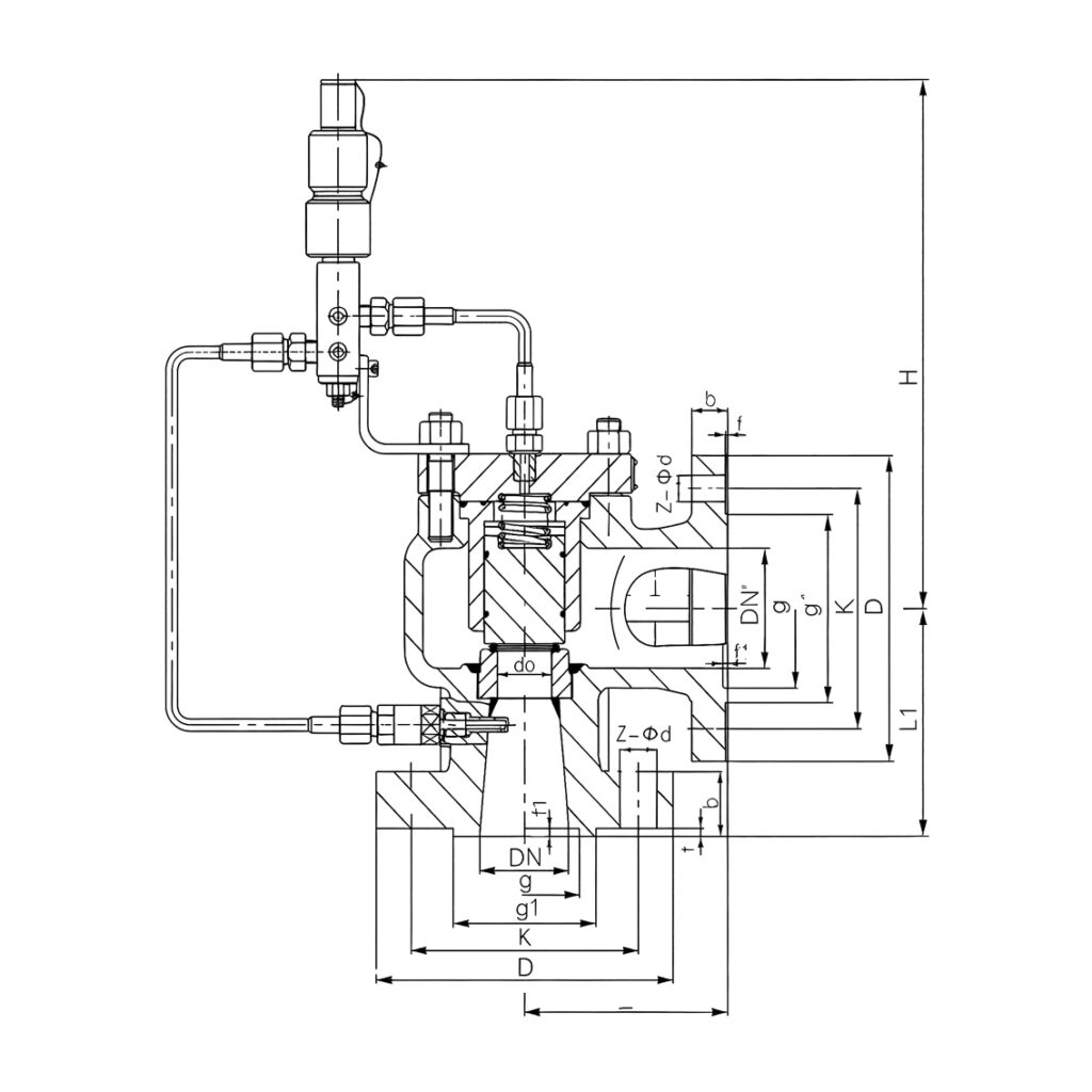
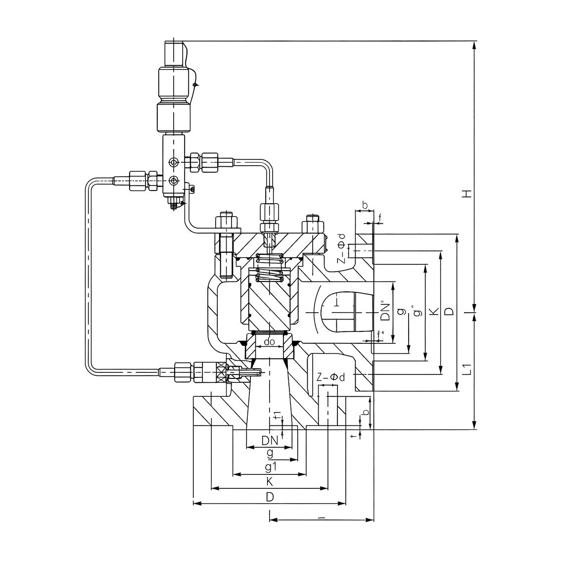
Dimensions – PN16 / PN25 / PN40
| DN | Outlet DN′ | Orifice d₀ (mm) | L (mm) | L₁ (mm) | H Approx. (mm) |
| 25 | 32 | 15 | 110 | 95 | 355 |
| 25 | 50 | 15 | 114 | 105 | 382 |
| 32 | 40 | 20 | 115 | 105 | 382 |
| 40 | 50 | 25 | 121 | 124 | 390 |
| 50 | 65 | 32 | 135 | 120 | 430 |
| 50 | 80 | 33 | 124 | 137 | 430 |
| 65 | 80 | 40 | 160 | 140 | 440 |
| 80 | 100 | 50 | 162 | 156 | 440 |
| 100 | 125 | 65 | 205 | 160 | 455 |
| 100 | 150 | 65 | 210 | 197 | 455 |
| 150 | 200 | 100 | 241 | 240 | 488 |
| 200 | 250 | 125 | 279 | 276 | 525 |
Dimensions – PN64 / PN100
| DN | Outlet DN′ | Orifice d₀ (mm) | L (mm) | L₁ (mm) | H Approx. (mm) |
| 25 | 32 | 15 | 110 | 100 | 372 |
| 25 | 50 | 15 | 114 | 111 | 385 |
| 32 | 40 | 20 | 130 | 110 | 398 |
| 40 | 50 | 25 | 121 | 124 | 410 |
| 50 | 65 | 32 | 160 | 130 | 445 |
| 50 | 80 | 32 | 124 | 137 | 458 |
| 65 | 80 | 40 | 175 | 160 | 485 |
| 80 | 100 | 50 | 162 | 162 | 496 |
| 100 | 125 | 65 | 195 | 195 | 520 |
| 100 | 150 | 65 | 210 | 197 | 538 |
| 150 | 200 | 100 | 241 | 246 | 638 |
| 200 | 250 | 125 | 279 | 297 | 715 |
Dimensions – PN160
| DN | Outlet DN′ | Orifice d₀ (mm) | L (mm) | L₁ (mm) | H Approx. (mm) |
| 25 | 50 | 13 | 121 | 126 | 445 |
| 40 | 50 | 16 | 140 | 149 | 460 |
| 50 | 80 | 32 | 171 | 167 | 490 |
| 80 | 100 | 48 | 181 | 191 | 500 |
| 100 | 150 | 60 | 233 | 249 | 540 |
Dimensions are for preliminary engineering and layout reference. Final approved dimensional drawings should be confirmed before piping fabrication or installation.
Some inlet sizes are available with more than one outlet DN′ configuration, and the supplied dimensional data also shows different orifice sizes for certain configurations. The required inlet, outlet and orifice combination should therefore be confirmed during final valve sizing.
Pilot-Operated Safety Valve Selection
For correct selection of the TT-A46Y/F, provide:
- Process medium
- Gas or liquid composition
- Set pressure
- Normal operating pressure
- Design pressure
- Operating temperature
- Relieving temperature
- Required relieving capacity
- Superimposed back pressure
- Built-up back pressure
- Maximum total back pressure
- Required inlet DN
- Required outlet DN
- Pressure rating
- Required material configuration
- Seat material requirement
- Pilot tubing material
- Whether online set-pressure checking is required
- Applicable standards and certification requirements
- Discharge header arrangement
For applications where normal operating pressure is close to the set pressure, the maximum normal operating pressure should be clearly stated during selection.
Engineering Support
THINKTANK supports EPC contractors, oil & gas companies, chemical plants, process licensors, pressure equipment manufacturers and system integrators with:
- Pilot-operated safety valve sizing and selection
- Relieving capacity calculation
- Back-pressure evaluation
- Set-pressure and blowdown configuration
- Material selection
- Soft-seat compatibility review
- Pilot system configuration
- Online test and calibration arrangement
- Dimensional drawings
- 3D models for system integration
- Existing pilot-operated safety valve replacement evaluation
- Project-specific technical documentation
With more than 30 years of industrial valve application experience, THINKTANK can provide application review and equivalent replacement solutions for pilot-operated safety relief valves used in demanding pressure-protection systems.