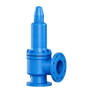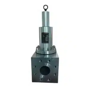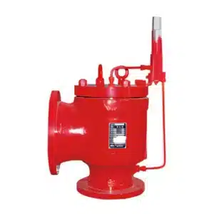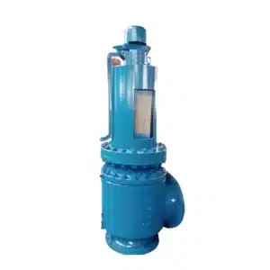


Product Overview
The THINKTANK TT-A37H / A43H Series is a dual low-lift safety valve assembly designed for automatic overpressure protection of equipment and piping systems handling steam, air and similar compatible media.
The assembly consists of two TT-A47H spring-loaded low-lift safety valves of the same model and size mounted on a common Y-type junction.
The nominal size of the TT-A37H / A43H assembly refers to the inlet diameter of the Y-type junction, rather than the inlet size of each individual TT-A47H branch valve.
The series is available in main inlet sizes from DN50 to DN150, with nominal pressure ratings of PN16, PN25 and PN40.
The listed maximum operating temperature is 350°C.
Assembly Configuration
The supplied product data defines the assembly as:
TT-A37H = 2 × TT-A47H + Y-type junction
TT-A43H = 2 × TT-A47H + Y-type junction
Two TT-A47H safety valves of the same size are installed on the two branches of the Y-type inlet body.
The Y-type junction receives pressure from a common equipment or piping connection and distributes it to the two spring-loaded safety valves.
This arrangement provides two parallel relieving paths within one safety valve assembly.
The final required relieving capacity must be verified according to the actual set pressure, medium and process conditions.
TT-A37H vs. TT-A43H
The TT-A37H and TT-A43H use the same general dual-valve arrangement but have different branch-valve size combinations for certain main inlet sizes.
For example:
- TT-A37H DN80 uses two TT-A47H DN65 branch valves
- TT-A43H DN80 uses two TT-A47H DN50 branch valves
Therefore, TT-A37H and TT-A43H should not be considered dimensionally or hydraulically identical merely because the common Y-junction inlet DN is the same.
The appropriate configuration should be selected according to the required relieving capacity and approved sizing data.
Quick Specifications
| Parameter | Specification |
|---|---|
| Model | TT-A37H / TT-A43H |
| Product Type | Dual Spring-Loaded Safety Valve Assembly |
| Lift Type | Low Lift |
| Branch Safety Valve | TT-A47H |
| Assembly Configuration | 2 × TT-A47H + Y-Type Junction |
| Main Inlet Size Range | DN50–DN150 |
| Pressure Rating | PN16 / PN25 / PN40 |
| Connection | Flanged |
| Applicable Media | Steam, air and similar media |
| Maximum Operating Temperature | ≤350°C |
| Main DN Definition | Y-type junction inlet diameter |
| Manufacturer | THINKTANK |
How It Works
During normal operation, both TT-A47H branch safety valves remain closed under spring force.
Pressure from the protected equipment enters the common Y-type junction and is transmitted to the inlet of both branch safety valves.
When system pressure reaches the specified set pressure, the pressure force acting on the valve discs overcomes the spring force and the safety valves open according to their operating characteristics.
The process medium is discharged through the two relief paths, reducing pressure in the protected system.
As the system pressure subsequently decreases into the reseating range, spring force returns the discs toward their seats and the valves reclose automatically.
Low-Lift Design
The TT-A37H / A43H assembly uses TT-A47H low-lift safety valves on both branches.
Under the general performance criteria applicable to this safety valve family:
Lift H ≥ 1/20 d₀
where:
- H = Valve lift
- d₀ = Orifice diameter of each individual branch valve
The dimensional table identifies the orifice arrangement using values such as 2 × 25, 2 × 65 and 2 × 100, indicating two branch-valve orifices within the dual assembly.
The total relieving capacity must be established from the approved capacity of the complete dual-valve configuration rather than simply selecting the assembly according to the common inlet DN.
Typical Applications
The TT-A37H / A43H Series can be considered for:
- Steam systems
- Compressed air systems
- Industrial gas systems
- Pressure vessels
- Process piping
- Utility systems
- Packaged equipment
- Skid-mounted systems
- Applications requiring a dual safety valve arrangement on a common inlet connection
Final selection should consider the medium, set pressure, operating temperature, required relieving capacity, back pressure and discharge piping arrangement.
General Performance Requirements
| Applicable Medium | Shell Test Pressure Ps | Seal Test Pressure Pm | Blowdown ΔP | Discharge Pressure Pp | Lift Height H |
| Steam | — | 90% Pk or the minimum reseating pressure, whichever is lower | When Pk ≤ 0.4 MPa: ΔP ≤ 0.04 MPa; when Pk > 0.4 MPa: ΔP ≤ 10% Pk | ≤ 1.03 Pk | Full-lift: ≥ 1/4 d₀; Low-lift: ≥ 1/20 d₀ |
| Air or other gases | 1.5 PN | When Pk ≤ 0.3 MPa: Pm = Pk − 0.03 MPa; when Pk > 0.3 MPa: Pm = 90% Pk | When Pk ≤ 0.2 MPa: ΔP ≤ 0.03 MPa; when Pk > 0.2 MPa: ΔP ≤ 15% Pk | ≤ 1.1 Pk | Full-lift: ≥ 1/4 d₀; Low-lift: ≥ 1/20 d₀ |
| Water or other liquids | — | When Pk ≤ 0.3 MPa: Pm = Pk − 0.06 MPa; when Pk > 0.3 MPa: Pm = 80% Pk | When Pk ≤ 0.3 MPa: ΔP ≤ 0.06 MPa; when Pk > 0.3 MPa: ΔP ≤ 20% Pk | ≤ 1.2 Pk | Full-lift: ≥ 1/4 d₀; Low-lift: ≥ 1/20 d₀ |
Notes:
- Pk = Set pressure
- d₀ = Orifice diameter
- PN = Nominal pressure
- Actual test and performance requirements shall be confirmed according to the selected assembly, project specification and applicable standard.
- For the TT-A37H / A43H, the low-lift criterion applies to each TT-A47H branch valve.
Dimensions – TT-A37H

Pressure Rating: PN16 / PN25 / PN40
| DN | L (mm) | L₁ (mm) | B (mm) | Outlet DN′ | Orifice d₀ | H Approx. (mm) |
| 50 | 115 | 225 | 165 | 32 | 2 × 25 | 310 |
| 80 | 140 | 310 | 205 | 65 | 2 × 50 | 415 |
| 100 | 160 | 355 | 255 | 80 | 2 × 65 | 420 |
| 125 | 170 | 400 | 275 | 100 | 2 × 80 | 540 |
| 150 | 190 | 440 | 300 | 125 | 2 × 100 | 625 |
Dimensions – TT-A43H
Pressure Rating: PN16 / PN25 / PN40
| DN | L (mm) | L₁ (mm) | B (mm) | Outlet DN′ | Orifice d₀ | H Approx. (mm) |
| 50 | 115 | 225 | 165 | 32 | 2 × 25 | 310 |
| 80 | 135 | 285 | 190 | 50 | 2 × 40 | 380 |
| 100 | 160 | 355 | 255 | 80 | 2 × 65 | 420 |
| 125 | 170 | 400 | 275 | 100 | 2 × 80 | 540 |
| 150 | 190 | 440 | 300 | 125 | 2 × 100 | 625 |
Dimensions are for preliminary engineering and layout reference. Final approved dimensional drawings should be confirmed before piping fabrication or installation.
Branch Valve Size Relationship
The nominal diameter of the TT-A37H / A43H refers to the common Y-junction inlet, while each branch uses a smaller TT-A47H safety valve.
| Dual Assembly Main DN | TT-A37H Branch TT-A47H DN | TT-A43H Branch TT-A47H DN |
| 50 | 32 | 32 |
| 80 | 65 | 50 |
| 100 | 80 | 80 |
| 125 | 100 | 100 |
| 150 | 125 | 125 |
This relationship is important when checking replacement valves, spare parts and individual branch-valve dimensions.
Dual Safety Valve Selection
For correct selection of the TT-A37H / A43H assembly, provide:
- Required model: TT-A37H or TT-A43H
- Process medium
- Set pressure
- Operating pressure
- Design pressure
- Operating temperature
- Relieving temperature
- Required total relieving capacity
- Required common inlet DN
- Back pressure
- Required pressure rating
- Discharge piping arrangement for both branch valves
- Required materials
- Applicable standards or certification requirements
- Installation orientation and available space
The total required relieving capacity should be verified against the capacity of the complete two-valve assembly.
Both branch valves should also be specified consistently according to the approved assembly configuration.
Engineering Support
THINKTANK supports EPC contractors, system integrators, boiler and pressure equipment manufacturers and industrial users with:
- Dual safety valve assembly sizing and selection
- Total relieving capacity review
- TT-A37H vs. TT-A43H configuration selection
- Branch TT-A47H sizing
- Set-pressure configuration
- Material selection
- Y-type junction engineering
- Dimensional drawings
- 3D models for system integration
- Existing dual safety valve replacement evaluation
- Project-specific technical documentation
With more than 30 years of industrial valve application experience, THINKTANK can support engineered safety valve assemblies and equivalent replacement solutions for steam, air and industrial gas pressure-protection systems.