Description
Brief of DIN Globe Valve
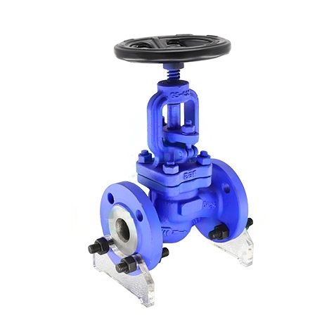
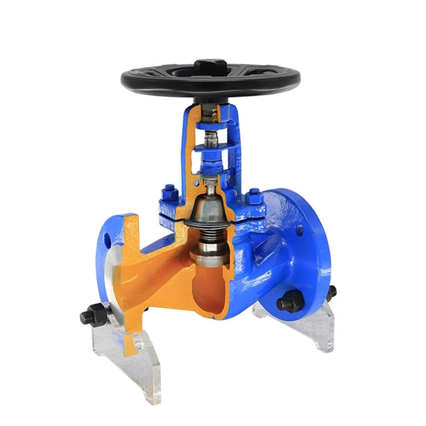
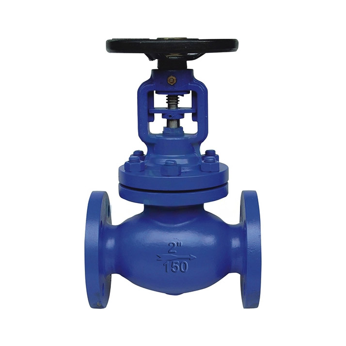
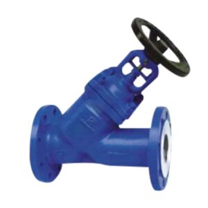
THINKTANK DIN Globe Valve is engineered to comply with the stringent DIN specifications, ensuring consistent quality and reliability. The innovative bellows design provides superior leak protection, extending the valve’s service life and reducing maintenance requirements.
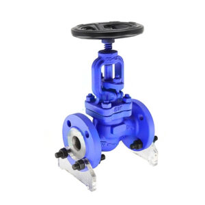
Key Features of DIN Globe Valve
- Construction: DIN globe valves are typically made of cast iron, ductile iron, carbon steel, stainless steel, or other materials suitable for the intended application. These materials are chosen for their durability, corrosion resistance, and ability to withstand high pressures and temperatures.
- Functionality: DIN globe valves are used to regulate the flow of fluid in a pipeline by adjusting the position of the valve disc, which is connected to a stem. The stem is operated manually, pneumatically, or electrically, depending on the application and requirements.
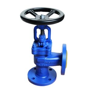
- Design: DIN globe valves are available in various designs, including straight pattern, angle pattern, and Y-pattern. The straight pattern is the most common, with the inlet and outlet ports aligned in a straight line. The angle pattern has the inlet and outlet ports forming a right angle, while the Y-pattern features a 45-degree angle between the inlet and outlet ports. The choice of design depends on the specific application, flow characteristics, and pressure drop requirements.
- Sealing: DIN globe valves can have different types of sealing systems, such as metal-to-metal, metal-to-PTFE (Teflon), or metal-to-elastomer. The sealing system determines the valve’s leakage class and suitability for different applications.
- Pressure Ratings: DIN globe valves are available in various pressure ratings, typically ranging from PN 10 to PN 400. The pressure rating indicates the maximum allowable pressure that the valve can withstand.
- End Connections: DIN globe valves can have various end connections, such as flanged, threaded, or welded, depending on the pipeline requirements and installation procedures.
Advantage THINKTANK DIN Globe Valve
- The bellows component is a crucial element of below-sealed valves, which is securely attached to both the valve bonnet and valve stem through a sophisticated automatic roll welding process. This metal bellows construction ensures a 100% leak-free stem area.
- The double seal design incorporates both bellows and packing components. The metal bellows form a primary barrier to prevent leakage, while the packing serves as a secondary sealing mechanism in the event of bellows failure.
- The overlay welded seat guarantees reliable sealing performance, even in the most demanding conditions.
- The valve features an ergonomic handwheel, designed for enhanced durability and ease of operation.
Technical Specifications
- Design standard: DIN EN 13709:2002
- Face to face dimension: DIN EN 558-1:1995
- Flanged ends: DIN EN 1092-1:2002
- Welded ends: DIN EN 12627
- Test& inspection: DIN EN 12266:2003
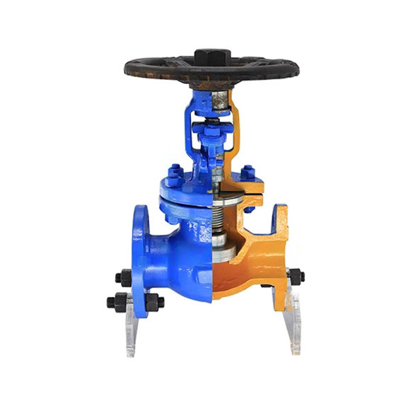
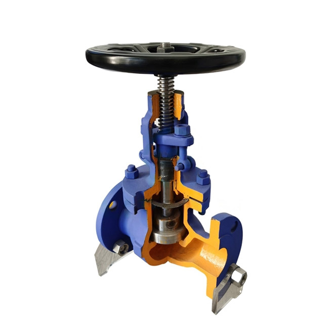
Parts of DIN Globe Valve
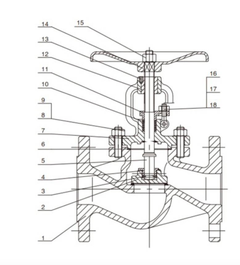
| No. | Parts Name | Materials |
| 1 | Body | GS-C25+13Cr |
| 2 | Disc | A105+13Cr |
| 3 | Pin | A3 |
| 4 | Disc cover | GS-C25 |
| 5 | Stem | 2Cr13 |
| 6 | Gasket | SS+Flexible graphite |
| 7 | Bonnet | GS-C25 |
| 8 | Nut | A194 2H |
| 9 | Bolt | A193 B7 |
| 10 | Packing | Flexible graphite |
| 11 | Gland | GS-C25 |
| 12 | Stem nut | QT400-15 |
| 13 | Lock srcew | A3 |
| 14 | Hand wheel | QT400-18 |
| 15 | Locknut | A194 2H |
| 16 | Nut | A194 2H |
| 17 | Eyebolt | A3 |
| 18 | Pin | A3 |
DIN Globe Valve Dimensions
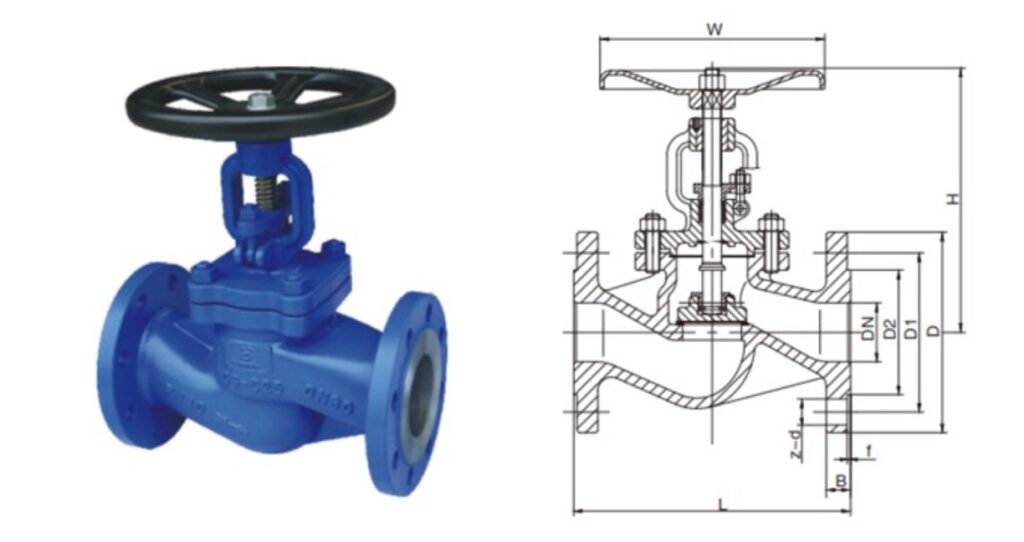
| PN16 | ||||||||||||||||
| DN | 15 | 20 | 25 | 32 | 40 | 50 | 65 | 80 | 100 | 125 | 150 | 200 | 250 | 300 | 350 | 400 |
| L RF/BW | 130 | 150 | 160 | 180 | 200 | 230 | 290 | 310 | 350 | 400 | 480 | 600 | 730 | 850 | 980 | 1100 |
| D | 95 | 105 | 115 | 140 | 150 | 165 | 185 | 200 | 220 | 250 | 285 | 340 | 405 | 480 | 520 | 580 |
| w | 140 | 140 | 160 | 160 | 180 | 200 | 220 | 250 | 300 | 350 | 400 | 450 | 550 | 600 | 700 | 700 |
| H | 195 | 195 | 215 | 219 | 247 | 256 | 282 | 305 | 385 | 430 | 470 | 650 | 775 | 852 | 1005 | 1140 |
| Weight(kg) | 4.2 | 5.1 | 6.2 | 8.2 | 9.8 | 13 | 17.5 | 23 | 37 | 53 | 82 | 140 | 252 | 310 | 540 | 760 |
| Kvs(m3/h) | 4.2 | 7.4 | 12 | 19 | 30 | 47 | 77 | 120 | 188 | 285 | 410 | 725 | 1140 | 1660 | 2230 | 2950 |
| PN25 | ||||||||||||||||
| DN | 15 | 20 | 25 | 32 | 40 | 50 | 65 | 80 | 100 | 125 | 150 | 200 | 250 | 300 | 350 | 400 |
| L RF/BW | 130 | 150 | 160 | 180 | 200 | 230 | 290 | 310 | 350 | 400 | 480 | 600 | 730 | 850 | 980 | 1100 |
| D | 95 | 105 | 115 | 140 | 150 | 165 | 185 | 200 | 235 | 270 | 300 | 360 | 425 | 485 | 555 | 620 |
| w | 140 | 140 | 160 | 160 | 180 | 200 | 220 | 250 | 300 | 350 | 400 | 450 | 550 | 600 | 700 | 700 |
| H | 195 | 195 | 215 | 219 | 247 | 256 | 282 | 305 | 385 | 430 | 470 | 650 | 775 | 852 | 1005 | 1140 |
| Weight(kg) | 4.2 | 5.1 | 6.2 | 8.2 | 9.8 | 13 | 18 | 24 | 38 | 55 | 85 | 146 | 265 | 330 | 580 | 790 |
| Kvs(m3/h) | 4.2 | 7.4 | 12 | 19 | 30 | 47 | 77 | 120 | 188 | 285 | 410 | 725 | 1140 | 1660 | 2230 | 2950 |
| PN40 | ||||||||||||||||
| DN | 15 | 20 | 25 | 32 | 40 | 50 | 65 | 80 | 100 | 125 | 150 | 200 | 250 | 300 | 350 | 400 |
| L RF/BW | 130 | 150 | 160 | 180 | 200 | 230 | 290 | 310 | 350 | 400 | 480 | 600 | 730 | 850 | 980 | 1100 |
| D | 95 | 105 | 115 | 140 | 150 | 165 | 185 | 200 | 235 | 270 | 300 | 375 | 450 | 515 | 580 | 660 |
| w | 140 | 140 | 160 | 160 | 180 | 200 | 220 | 250 | 300 | 350 | 400 | 450 | 550 | 600 | 700 | 700 |
| H | 195 | 195 | 215 | 219 | 247 | 256 | 282 | 305 | 385 | 430 | 470 | 650 | 775 | 852 | 1005 | 1140 |
| Weight(kg) | 4.2 | 5.1 | 6.2 | 8.2 | 9.8 | 13 | 19 | 25 | 40 | 57 | 88 | 148 | 280 | 350 | 620 | 830 |
| Kvs(m3/h) | 4.2 | 7.4 | 12 | 19 | 30 | 47 | 77 | 120 | 188 | 285 | 410 | 725 | 1140 | 1660 | 2230 | 2950 |
Available Disc Types
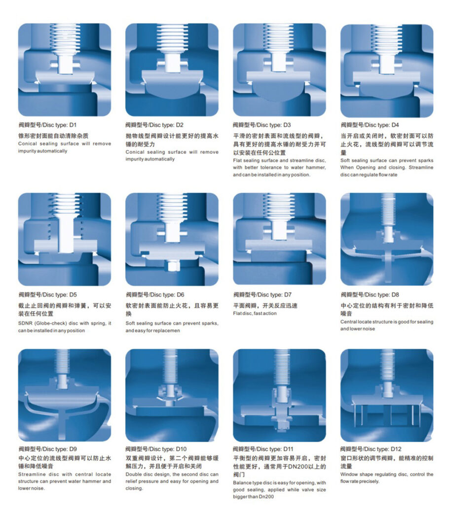
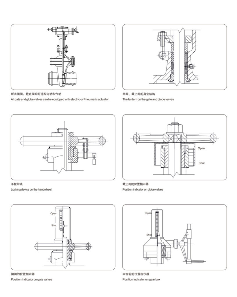
Special Design On Handwheel
