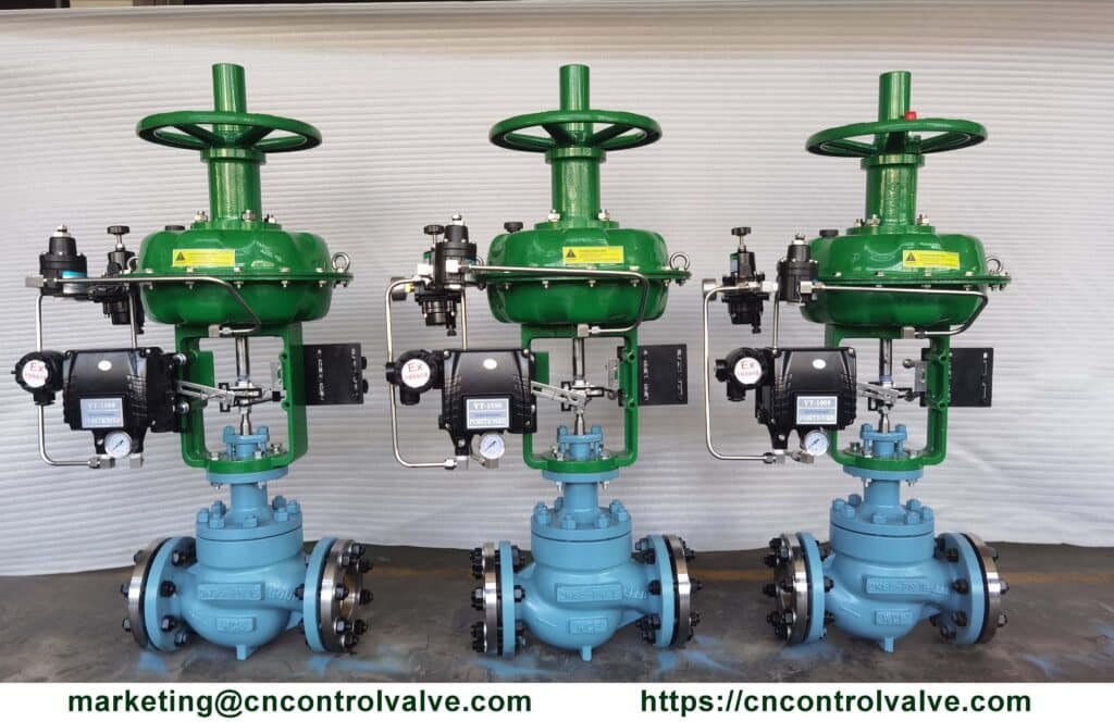
A control valve has two main parts: an actuator and a valve. The actuator controls the movement of the valve stem, while the pilot valve senses the pressure inside the pipe and opens and closes the valve accordingly.

In order to maintain constant pressure throughout the entire piping system, a control valve should be installed on each processing system.
The control valves regulate the flow of water through pipes by opening and closing in response to changes in pressure. The valves also allow for adjustments to the amount of water flowing through the pipe.
Control Valve Pressure-Temperature Chart
Pressure control valves are used in a wide range of applications where accurate control of fluid pressures is required. They are often used in situations where a constant flow rate, pressure, or temperature is desired. In these cases, the flow rate can be controlled by a valve with constant opening size. This type of valve is commonly known as a “pressure control valve”. Different temperatures bear different pressure ratings for control valves, the following chart is the pressure-temperature relationship of control valves.
Control Valve Pressure-Temperature Chart for Standard Class ASTM A216 Grade WCC Cast Steel In Accordance with ASME B16.34-2013
| Temperature | Class 150 | Class 300 | Class 600 | Class 900 | Class 1500 |
| °C | Bar | ||||
| -29 to 38 | 19.8 | 51.7 | 103.4 | 155.1 | 258.6 |
| 50 | 19.5 | 51.7 | 103.4 | 155.1 | 258.6 |
| 100 | 17.7 | 51.5 | 103.0 | 154.6 | 257.6 |
| 150 | 15.8 | 50.2 | 100.3 | 150.5 | 250.8 |
| 200 | 13.8 | 48.6 | 97.2 | 145.8 | 243.2 |
| 250 | 12.1 | 46.3 | 92.7 | 139.0 | 231.8 |
| 325 | 9.3 | 41.4 | 82.6 | 124.0 | 206.6 |
| 350 | 8.4 | 40.0 | 80.0 | 120.1 | 200.1 |
| 375 | 7.4 | 37.8 | 75.7 | 113.5 | 189.2 |
| 400 | 6.5 | 34.7 | 69.4 | 104.2 | 173.6 |
| 425 | 5.5 | 28.8 | 57.5 | 86.3 | 143.8 |
| °F | psig | ||||
| -20 to 100 | 290 | 750 | 1,500 | 2,250 | 3,750 |
| 200 | 260 | 750 | 1,500 | 2,250 | 3,750 |
| 300 | 230 | 730 | 1,455 | 2,185 | 3,640 |
| 400 | 200 | 705 | 1,405 | 2,110 | 3,520 |
| 500 | 170 | 665 | 1,330 | 1,995 | 3,325 |
| 600 | 140 | 605 | 1,210 | 1,815 | 3,025 |
| 650 | 125 | 590 | 1,175 | 1,765 | 2,940 |
| 700 | 110 | 555 | 1,110 | 1,665 | 2,775 |
| 750 | 95 | 505 | 1,015 | 1,520 | 2,535 |
| 800 | 80 | 410 | 825 | 1,235 | 2,055 |
Control Valve Pressure-Temperature Chart for Standard Class ASTM A217 Grade WC9 Cast Steel In Accordance with ASME B16.34-2013
| Temperature | Class 150 | Class 300 | Class 600 | Class 900 | Class 1500 |
| °C | Bar | ||||
| -29 to 38 | 19.8 | 51.7 | 103.4 | 155.1 | 258.6 |
| 50 | 19.5 | 51.7 | 103.4 | 155.1 | 258.6 |
| 100 | 17.7 | 51.5 | 103.0 | 154.6 | 257.6 |
| 150 | 15.8 | 50.3 | 100.3 | 150.6 | 250.8 |
| 200 | 13.8 | 48.6 | 97.2 | 145.8 | 243.4 |
| 250 | 12.1 | 46.3 | 92.7 | 139.0 | 321.8 |
| 300 | 10.2 | 42.9 | 85.7 | 128.6 | 214.4 |
| 325 | 9.3 | 41.4 | 82.6 | 124.0 | 206.6 |
| 350 | 8.4 | 40.3 | 80.4 | 120.7 | 201.1 |
| 375 | 7.4 | 38.9 | 77.6 | 116.5 | 194.1 |
| 400 | 6.5 | 36.5 | 73.3 | 109.8 | 183.1 |
| 425 | 5.5 | 35.2 | 70.0 | 105.1 | 175.1 |
| 450 | 4.6 | 33.7 | 67.7 | 101.4 | 169.0 |
| 475 | 3.7 | 31.7 | 63.4 | 95.1 | 158.2 |
| 500 | 2.8 | 28.2 | 56.5 | 84.7 | 140.9 |
| 538 | 1.4 | 18.4 | 36.9 | 55.3 | 92.2 |
| °F | psig | ||||
| -20 to 100 | 290 | 750 | 1,500 | 2,250 | 3,750 |
| 200 | 260 | 750 | 1,500 | 2,250 | 3,750 |
| 300 | 230 | 730 | 1,455 | 2,185 | 3,640 |
| 400 | 200 | 705 | 1,410 | 2,115 | 3,530 |
| 500 | 170 | 665 | 1,330 | 1,995 | 3,325 |
| 600 | 140 | 605 | 1,210 | 1,815 | 3,025 |
| 650 | 125 | 590 | 1,175 | 1,765 | 2,940 |
| 700 | 110 | 570 | 1,135 | 1,705 | 2,840 |
| 750 | 95 | 530 | 1,065 | 1,595 | 2,660 |
| 800 | 80 | 510 | 1,015 | 1,525 | 2,540 |
| 850 | 65 | 485 | 975 | 1,460 | 2,435 |
| 900 | 50 | 450 | 900 | 1,350 | 2,245 |
| 950 | 35 | 385 | 755 | 1,160 | 1,930 |
| 1000 | 20 | 265 | 535 | 800 | 1,335 |
| 1050 | 20(1) | 175 | 350 | 525 | 875 |
| 1100 | 20(1) | 110 | 220 | 330 | 550 |
Control Valve Pressure-Temperature Chart for Standard Class ASTM A351 Grade CF3 Cast Steel In Accordance with ASME B16.34-2013
| Temperature | Class 150 | Class 300 | Class 600 | Class 900 | Class 1500 |
| °C | Bar | ||||
| -29 to 38 | 19.0 | 49.6 | 99.3 | 148.9 | 248.2 |
| 50 | 18.3 | 47.8 | 95.6 | 143.5 | 239.1 |
| 100 | 15.7 | 40.9 | 81.7 | 122.6 | 204.3 |
| 150 | 14.2 | 37.0 | 74.0 | 111.0 | 185.0 |
| 200 | 13.2 | 34.5 | 69.0 | 103.4 | 172.4 |
| 250 | 12.1 | 32.5 | 65.0 | 97.5 | 162.4 |
| 325 | 9.3 | 30.2 | 60.4 | 90.7 | 151.1 |
| 350 | 8.4 | 29.6 | 59.3 | 88.9 | 148.1 |
| 375 | 7.4 | 29.0 | 58.1 | 87.1 | 145.2 |
| 400 | 6.5 | 28.4 | 56.9 | 85.3 | 142.2 |
| 425 | 5.5 | 28.0 | 56.0 | 84.0 | 140.0 |
| °F | psig | ||||
| -20 to 100 | 275 | 720 | 1,440 | 2,160 | 3,600 |
| 200 | 230 | 600 | 1,200 | 1,800 | 3,000 |
| 300 | 205 | 540 | 1,075 | 1,615 | 2,690 |
| 400 | 190 | 495 | 995 | 1,490 | 2,485 |
| 500 | 170 | 465 | 930 | 1,395 | 2,330 |
| 600 | 140 | 440 | 885 | 1,325 | 2,210 |
| 650 | 125 | 430 | 865 | 1,295 | 2,160 |
| 700 | 110 | 420 | 845 | 1,265 | 2,110 |
| 750 | 95 | 415 | 825 | 1,240 | 2,065 |
| 800 | 80 | 405 | 810 | 1,215 | 2,030 |
Control Valve Pressure-Temperature Chart for Standard Class ASTM A351 Grades CF8M and CG8M(1) Cast Steel In Accordance with ASME B16.34-2013
| Temperature | Class 150 | Class 300 | Class 600 | Class 900 | Class 1500 |
| °C | Bar | ||||
| -29 to 38 | 19.0 | 49.6 | 99.3 | 148.9 | 248.2 |
| 50 | 18.4 | 48.1 | 96.2 | 144.3 | 240.6 |
| 100 | 16.2 | 42.2 | 84.4 | 126.6 | 211.0 |
| 150 | 14.8 | 38.5 | 77.0 | 115.5 | 192.5 |
| 200 | 13.7 | 35.7 | 71.3 | 107.0 | 178.3 |
| 250 | 12.1 | 33.4 | 66.8 | 100.1 | 166.9 |
| 300 | 10.2 | 31.6 | 63.2 | 94.9 | 158.1 |
| 325 | 9.3 | 30.9 | 61.8 | 92.7 | 154.4 |
| 350 | 8.4 | 30.3 | 60.7 | 91.0 | 151.6 |
| 375 | 7.4 | 29.9 | 59.8 | 89.6 | 149.4 |
| 400 | 6.5 | 29.4 | 58.9 | 88.3 | 147.2 |
| 425 | 5.5 | 29.1 | 58.3 | 87.4 | 145.7 |
| 450 | 4.6 | 28.8 | 57.7 | 86.5 | 144.2 |
| 475 | 3.7 | 28.7 | 57.3 | 86.0 | 143.4 |
| 500 | 2.8 | 28.2 | 56.5 | 84.7 | 140.9 |
| 538 | 1.4 | 25.2 | 50.0 | 75.2 | 125.5 |
| 550 | 1.4(2) | 25.0 | 49.8 | 74.8 | 124.9 |
| 575 | 1.4(2) | 24.0 | 47.9 | 71.8 | 119.7 |
| 600 | 1.4(2) | 19.9 | 39.8 | 59.7 | 99.5 |
| 625 | 1.4(2) | 15.8 | 31.6 | 47.4 | 79.1 |
| 650 | 1.4(2) | 12.7 | 25.3 | 38.0 | 63.3 |
| 675 | 1.4(2) | 10.3 | 20.6 | 31.0 | 51.6 |
| 700 | 1.4(2) | 8.4 | 16.8 | 25.1 | 41.9 |
| 725 | 1.4(2) | 7.0 | 14.0 | 21.0 | 34.9 |
| 750 | 1.4(2) | 5.9 | 11.7 | 17.6 | 29.3 |
| 775 | 1.4(2) | 4.6 | 9.0 | 13.7 | 22.8 |
| 800 | 1.2(2) | 3.5 | 7.0 | 10.5 | 17.4 |
| 816 | 1.0(2) | 2.8 | 5.9 | 8.6 | 14.1 |
| Temperature | Class 150 | Class 300 | Class 600 | Class 900 | Class 1500 |
| °C | Bar | ||||
| -20 to 100 | 275 | 720 | 1,440 | 2,160 | 3,600 |
| 200 | 235 | 620 | 1,240 | 1,860 | 3,095 |
| 300 | 215 | 560 | 1,120 | 1,680 | 2,795 |
| 400 | 195 | 515 | 1,025 | 1,540 | 2,570 |
| 500 | 170 | 480 | 955 | 1,435 | 2,390 |
| 600 | 140 | 450 | 900 | 1,355 | 2,255 |
| 650 | 125 | 440 | 885 | 1,325 | 2,210 |
| 700 | 110 | 435 | 870 | 1,305 | 2,170 |
| 750 | 95 | 425 | 855 | 1,280 | 2,135 |
| 800 | 80 | 420 | 845 | 1,265 | 2,110 |
| 850 | 65 | 420 | 835 | 1,255 | 2,090 |
| 900 | 50 | 415 | 830 | 1,245 | 2,075 |
| 950 | 35 | 385 | 775 | 1,160 | 1,930 |
| 1000 | 20 | 365 | 725 | 1,090 | 1,820 |
| 1050 | 20 | 360 | 720 | 1,080 | 1,800 |
| 1100 | 20(2) | 305 | 610 | 915 | 1,525 |
| 1150 | 20(2) | 235 | 475 | 710 | 1,185 |
| 1200 | 20(2) | 185 | 370 | 555 | 925 |
| 1250 | 20(2) | 145 | 295 | 440 | 735 |
| 1300 | 20(2) | 115 | 235 | 350 | 585 |
| 1350 | 20(2) | 95 | 190 | 290 | 480 |
| 1400 | 20(2) | 75 | 150 | 225 | 380 |
| 1450 | 20(2) | 60 | 115 | 175 | 290 |
| 1500 | 15(2) | 40 | 85 | 125 | 205 |
2. Flanged end ratings terminate at 538°C (1000°F) for CF8M.
Pressure Control Valve Characteristic

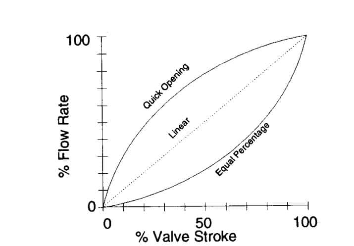
The flow characteristic of the control valve is the relationship between valve travel from 0% to 100% corresponding to the flow Cv/Kv value.
1. EQ% Characteristic (Equal Percentage Characteristic)
The ratio of the change in flow rate to the change in valve opening position is proportional to the flow rate before the change and is expressed by the following equation.
dCv/dL = KCv,
so Cv = eK(L-1)
2. Linear % Characteristic (Linear Characteristic)
With the linear characteristic, the valve opening position and the flow rate are proportional to each other.
Cv = KL
L is the valve opening position, and K is a constant.
3. Quick Opening Characteristic
The quick opening characteristic is a kind of on-off flow characteristic, an efficient characteristic that can be used to switch the flow rate between maximum and minimum.

The inherent flow characteristic of the control valve is the relationship between the flow and travel of the valve to a constant pressure drop across the valve.
What is valve gain?
The valve gain is the increased flow rate generated by an increasing change in plug position. This gain is a function of valve size and type, plug configuration, and system operating conditions. The gain at any point in the valve travel is equal to the slope of the valve flow characteristic curve at that point.
What are the Cv value and Kv value for the control valve?
The valve coefficient Cv is the number of US gallons per minute of water at 60 °F that will flow through a valve at a specific opening with a 1 psi pressure drop across the control valve. The flow factor Kv Flowrate in m³/h of water at between 25 °C will create a pressure drop of one bar across the control valve.


