Steam is an extremely versatile source of energy in industrial production, and the condensate generated after steam releases some of its heat energy is often wasted. Condensate has a large amount of heat, generally accounting for about 20-30% of the total heat of steam, and for some equipment, it can be as high as 40%. Therefore, if high-temperature condensate can be recycled as boiler make-up water or used for secondary flash steam, it not only saves industrial water but also saves a large amount of fuel. In this way, the boiler can save 30~40% of fuel, water, and water treatment supplies when producing the same amount of steam. Most importantly, the fuel savings reduce the amount of boiler flue gas emissions, thus better protecting the environment.
5 Major Values of Condensate Recovery
- Recovery of heat energy in condensate, secondary flash steam can replace new production steam heating materials.
- Saves water and water treatment costs.
- High-temperature condensate as boiler feed water, saving the boiler heating feed water consumed fuel.
- Condensate as boiler feed water, the TDS content is lower, reducing the number of boiler drains and reducing the heat loss taken away by the drains.
- Reduces the pollution of flue gas emissions and sewage water to soil and groundwater.
So let’s step by step learn the condensate return system, condensate & steam recovery equipment in this post.
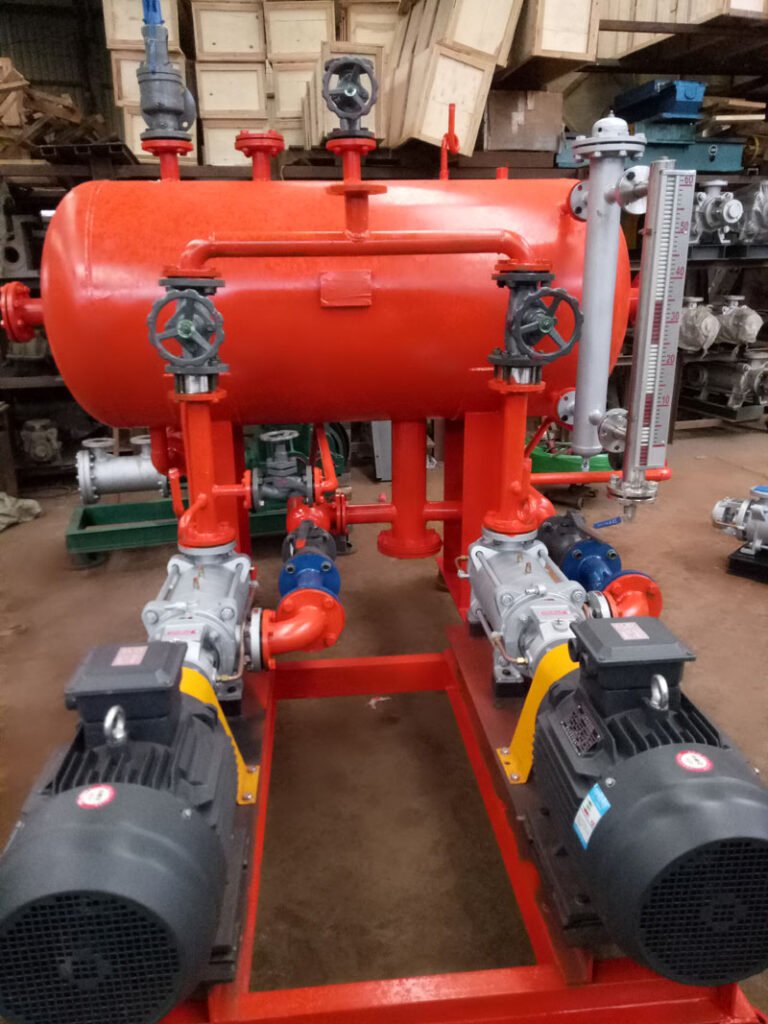
What Is Condensate
The condensed water is refined water. This substance is distilled water. It may contain residual chemical treatment but still has a high value. Most importantly, the water is hot. Obviously, it is less cost-effective to regenerate hot condensate into steam than it is to heat cold water into steam. Every thermal energy is valuable, and the thermal energy that remains in the condensate is no exception. Traditionally, just the primary steam process area was the focus of condensate removal. Condensate is made up of heat, chemicals, and water. Usually, it represents more than one-third of the cost of producing steam.
What are Condensate and Feedwater Storage
In industrial steam distribution networks and process equipment, condensate must be removed from the equipment as soon as possible because it impedes heat transfer and can cause water hammer. Failure to ensure that condensate is adequately drained from steam mains can lead to leaks at joints and water hammers, which can result in major steam line failures. Inadequate drainage of process equipment, on the other hand, can reduce the operating efficiency of the equipment, affecting productivity and profitability.
While draining condensate to the outside keeps the steam space clear, it is an expensive loss, not just in terms of lost heat and water, but also in terms of significantly increased production costs, wasted energy, and increased carbon emissions.
All condensate should be returned to the boiler room for reuse unless it is polluted.
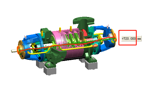
What is Condensate Recovery System and Condensate Return System
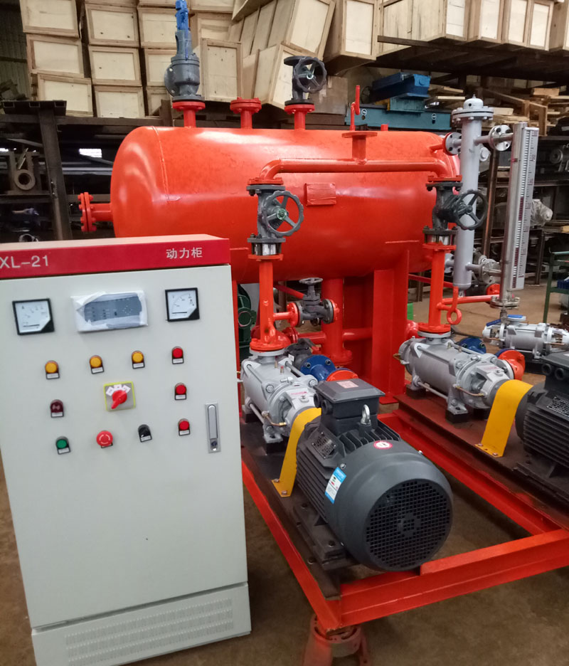
Condensate recovery and return systems collect and return condensate from steam operations to the feedwater storage tank.
The condensate recovery and return system absorbs and returns condensate from the steam cycle to the feedwater tank.
To best meet the needs of your steam systems, a variety of applications are covered by rectangular or cylindrical tank designs with on-skid electrical or built-in mechanical steam booster pumps.
Why Recover Condensate
20% of the heat that was used to create the steam is found in the condensate that results when steam releases its latent heat. Recovery of condensate will result in considerable savings in the boiler feed water, water treatment chemicals, and boiler blowdown in addition to significantly enhancing the system’s overall thermal balance.
Therefore, it is wise to make sure that all condensate is collected and returned to the boiler house whenever available. When condensate must be released to drain for financial reasons, every effort should be taken to remove the heat energy.
The resource condensate is quite precious. It should be added back to the feedwater system because of the high heat energy.
- Condensate has previously undergone treatment, which lowers the cost of water treatment.
- Condensate disposal’s exorbitant expense is avoided.
- Because fresh water is not constantly being fed to the boiler, water costs are reduced.
- Fuel savings of up to 20% as a result.
Condensate Recovery Techniques
Solution A: Condensate Returning Using Steam Trap
Condensate can be conveyed to the storage tank at positive differential pressure using the steam trap’s inlet pressure as the driving force. The most reliable and economical recovery technique is this one. Since no specialized equipment is needed for it, the operation is rather simple.
- The essential equipment required is a steam trap and transport pipe since the differential pressure from gravity-driven downward drainage to an atmospheric system or vessel is always positive.
- The steam trap can discharge overhead to an elevated return as long as the differential pressure is positive and the necessary safety precautions are taken. Condensate removal from steam traps installed on primary utility steam lines is a typical example. As vertical and horizontal distances grow, the system back pressure also rises. If the differential pressure falls, the straightforward trap method will not work.
Cons of the Condensate Returning Using Steam Trap
- Capacity decreases as backpressure increases.
- To prevent condensate flooding within the machine, open the bypass valve.
- Leaking of live steam via the bypass.
- Increased steam usage during the procedure.
- Particularly harmful when steam traps are using various input pressures.
- Even if just one steam trap breaks, the entire system becomes pressured and ceases to operate.
Solution B: Using an Electric Pump
When the pressure differential from source to destination is negative, a typical centrifugal or turbine condensate pump can be utilized to boost delivery pressure and achieve positive differential pressure. Pumping enables the transfer and recovery of condensate across far longer and more extended distances. The condensate is initially collected in a tank and then electrically pumped to the reuse locations.
Cons of the Using an Electric Pump
- The reverse pressure on steam traps
- Venting of flash steam
- Radiative loss causes a drop in condensate temperature over the collection tank.
- Too numerous elements to sustain
- Cavitation and dry operating of electric pumps
- Expensive water treatment cost
- Low temperature of the feedwater
- Using electricity is the most expensive utility.
Solution C: Using a Steam/Air-operated Pump
Due to the mechanical condensate pumps’ reliance on positive displacement and lack of usage of an impeller, there is no risk of cavitation. Their size is less important since they are generally unaffected by significant variations in back pressure. They are also suitable for isolated regions and areas protected from explosions because they don’t need electricity.
In recent years, mechanical pumps’ varieties and capabilities have increased, which makes them one of the most often chosen techniques for recovering condensate.
Pros of the Using a Steam/Air-operated Pump
- The temperature at which condensate is pumped ranges from 950 to 1000C.
- 100% Quick recovery of steam
- Higher temperature of the feedwater.
- Lower need for makeup water
- Affordable chemical treatment
- Simply uses 3kg of steam for every ton of condensate.
- Deaerator: Ensures that makeup water, flash steam, and condensate are properly mixed.
- The boiler blowdown was minimized.
How to Lifting Condensate
The notion that steam traps lift condensate is untrue. Steam traps are mechanical devices that automatically release condensate while preventing steam wastage. The steam pressure at the trap provides the driving power needed to raise the condensate.
Why Handling Condensate
Condensate should be allowed to drain by gravity to vented receivers and be pumped back to the boiler feedwater tank in order to minimize water plugging of the steam system and decreased plant efficiency.
It would also be wise to have monitoring devices for large systems. While conductivity, PH, and turbidity monitoring stop polluted condensate from being reintroduced to the feed tank and causing issues inside the boilers, overflow alarms alert users to pump failure.
Steam Control Significantly Reduces Condensate Recovery Costs
Sean Ottewell writes that good management of Steam, a significant utility, is resulting in significant savings for customers.
Controlling the cost of the energy consumed during processing is particularly difficult since oil and gas prices continue to be unpredictably volatile. Rising energy costs may swiftly erode a process’s cost base, hurting its profitability and capacity to compete. Steam is a very efficient heating medium and a vital utility that supplies various application services. Over the years, many businesses have made investments to increase the efficiency of their steam systems. Condensate recovery has been one of the areas of attention. Condensate energy is frequently utilized to pre-heat boiler feed water, which reduces fuel costs and boosts boiler efficiency. In actuality, condensate recovery will reduce a boiler’s energy cost by 1% for every 6°C increase in temperature.
However, certain condensate recovery devices are so powerful that occasionally they catch too much energy. The typical feedwater temperature is just 85°C or 90°C while the boiler feed tank is operating at atmospheric pressure. Higher temperatures run the possibility of cavitation in the boiler feed pump, which might cause serious harm. As a result, the quantity of heat that may be introduced into the feed tank is naturally constrained. This may prevent certain plants from using the entire amount of condensate heat recovery, leaving them with no choice except to let it drain away.
This issue is resolved by a cutting-edge heat recovery system from Spirax Sarco, which seals off the whole steam system and transfers the heat from the recovered condensate and flash steam to the high-pressure side of the boiler feed pumps. Pump cavitation is not a problem when the temperature of the water entering the boiler is raised to much above 100°C.
The advantage is a substantial reduction in steam-raising expenses and an improvement in boiler efficiency. All water is recycled using the Spirax Sarco flash recovery energy management equipment (FREME) system, which lowers the cost of chemical and water treatment.
In an effort to reduce energy costs, Abbey Corrugated, the top sheet feeder for a corrugated board in the UK, hired Spirax Sarco to project manage the installation of a FREME system.
Water entered the boiler at about 68°C or 70°C prior to the project. According to facilities manager Paul Gale, it now arrives at between 138 and 142°C. “There was a lot of work going on at the time, but it’s fair to estimate that the savings from this project were in the region of 25% of the gas consumed by the boiler,” he said.
A flash steam separation vessel is used by the FREME system to process condensate from the steam distribution system. Before the pressurized feed water enters the boiler, the distinct streams of flash steam and condensate pass via a specialized plate heat exchanger where they heat the water. Once again merged, the two returning streams are then returned to the boiler feed tank. The combined stream is now sub-cooled, which means it is warm enough to start warming the cold feed but not hot enough to create cavitation in the feed pump.
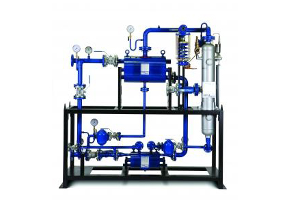
The FREME system may be delivered as a pre-engineered, skid-mounted system, alleviating the burden of planning, specifying, constructing, and installing steam, hot water, and other systems. Purchasing a full set from a single vendor guarantees that all components are exactly matched. This leads to an improved system’s efficiency, dependability, and precision. And because less labor is required on-site, the installation procedure is simplified, safer, and expedited.
What is a Condensate Transfer Pump
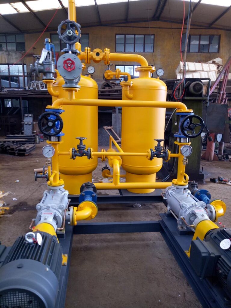
The condensate pump is a mechanism that collects condensate and pumps it using feed water generated from steam. The condensate pump is compatible with gas, compressed air, and steam. In high-pressure conditions, it can be utilized in a double–triple configuration. With the aid of these condensate pump systems, the system recovers the greatest amount of energy when the boiler feed water temperature is optimal. If electrical pumps are used instead of condensate pumps to deliver high-temperature condensate, flash steam will generate cavitations. To avoid this situation in the system, a mechanical condensate pump must be utilized.
Work Principles of Condensate Pump
Condensate comes from the input collector and goes on the internal pipe and access check valve then enter in condensate pump body so the tank is getting full. In the tank when the condensate comes on the upper limit, the level gauge checks the conductivity and changes it to an electrical signal, and sends it to the 3-way pneumatic control valve for the giving contact which is on the steam line than allows it to be opened. Normally steam has more high pressure than condensate pressure. When the 3-way control valve is closed, the system discharge condensate from the system with the thermodynamic steam trap. Condensate enters the condensate pump body through the access check valve after exiting the internal pipe and input collector, filling the tank. When the condensate reaches its upper limit in the tank, the level gauge measures conductivity converts the result to an electrical signal and transmits it to the 3-way pneumatic control valve for the giving contact that is on the steam line, allowing it to be opened. Condensate pressure often isn’t as high as steam pressure. The system uses the thermodynamic steam trap to discharge condensate when the 3-way control valve is closed.
Brief
Plants that use a large amount of steam have inadequate or no use of both condensate and steam recycling. The actual investment in their recovery projects is small, but the benefits are particularly large. This paper discusses the reasons for the unpopularity of condensate recovery projects and the problems in project implementation from a technical level and provides a generic typical recovery scheme for the reader’s reference.
Keywords: Condensate, Vapor/Steam Recovery, Energy Efficiency
Heating Recovery Concept
- Waste heat recovery. It includes not only the recovery of condensate and spent steam, but also the recovery of flue gas, hot air, chemical gases, and solids containing heat. There are various methods of recovery, and this paper only talks about the heat recovery of steam and liquid water.
- Condensate recovery. Since the condensate is often in a saturated state, it cannot be directly transported by general pumps due to cavitation problems and requires the necessary technical means to complete the transport.
- Waste steam recovery is sometimes called residual steam recovery. The exhaust steam is the low-pressure waste steam that cannot be used directly in the process, or it may be the flash steam from the condensate. The flash steam is condensate (often in the saturated state) throttling pressure reduction when the steam is separated. The exhaust steam may also be a vapor-gas mixture from the drying and volatilization process of the material. The recovery of exhaust steam generally uses the water absorption method, but the generated hot water is often nowhere to be used, which is the “entropy excess” of this wide world problem.
Our recommended solution of boost recovery with a steam inducer provides an alternative path to solve the problem of excess entropy.
The main cost of production in many factories is energy, and the transformation of energy is in the form of steam and water, of which the amount that should be recovered but is not recycled is very significant, equivalent to millions of tons of steam per hour nationwide. The annual value of each ton of steam is more than one million China Yuan so the value of the nation’s annual waste is in the hundreds of billions of China Yuan. Moreover, the environmental degradation caused by this energy waste is immeasurable.
We often do recovery programs for plants, in which the benefit analysis section often concludes that the payback period is less than a year, or even a few dozen days or ten days to recover the investment. Many factory owners do not notice this, which is indeed a big loss, so THINKTANK started to focus on developing and investing in this market.
Existing Problems
1. If the recovery is pure hot water which not saturated state, and does not contain steam, only the pump pumping cavitation, and transport difficulties, in this case, no need to set up a tank, as long as an additional water jet (hereinafter referred to as WWJ), through the reflux diversion, enhance the pressure of the pump inlet, so that the cavitation margin exceeds the necessary cavitation margin of the pump can be, as shown in Figure 1.

In the figure: “high pressure conveying” and “low pressure conveying” according to the need to choose one of them can be. (Some plants still add tanks for recovery under this condition, which greatly increases investment and causes waste.
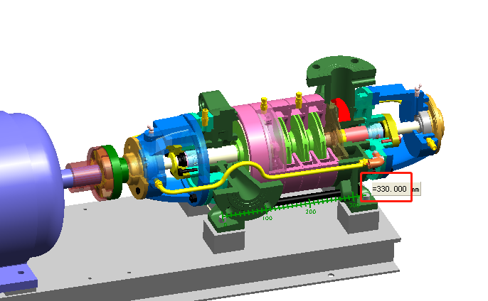
2. Water is saturated water, usually with almost no steam, but individual cases of steam, this situation is suitable for the current popular and common program, is also the use of WWJ to enhance the pressure, and increase the water subcooling method, but need to add a flash tank.
By the way, explain a few related thermodynamic concepts: one is “subcooling”, which refers to the difference between the saturation temperature of the water and the actual temperature, and the saturation temperature and pressure is the corresponding relationship, the higher the pressure, the higher the saturation temperature, power plants to increase the feed pump inlet water subcooling, the deaerator is located at a height of tens of meters, a large investment, perhaps there One day you can use the WWJ method to solve. Second, the “flash” is a certain temperature of hot water in a low-pressure environment, due to saturation boiling generated by the separation of vapor phenomenon.
In the case of water that may contain steam should be used in the flash tank, the steam will be separated out, and then the water recover. Otherwise, the steam will interfere with the work of the WWJ, can not add to the pump outlet pressure, and therefore can not achieve recovery at all.
There are usually three system options see Figure 2, Figure 3, Figure 4


One of the options in Figure 2 is to use WWJ to draw condensate into the tank, which prevents the condensate from climbing up the slope to produce water strikes and increases the operating pressure and temperature of the tank to avoid flash. The disadvantage is that once the tank is saturated with water, the pump can not work, there are many manufacturers that use this program.
Figure 3 program is a small amount of pump water to lead the tank out of the water to provide the pump with a subcooling degree of water intake, the advantage is that the tank even if there is a flash, the pump can still work properly.
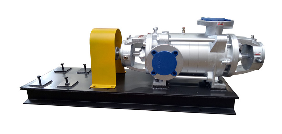
Figure 4 program is an improved version of the figure three program, that is, the external WWJ into the built-in, so that not only can save installation space, and the WWJ in the tank can also play a role in controlling the water level, that is, when the water level is low or even steam into the WWJ, the WWJ received interference will reduce the flow.
But the above three options are not able to solve the problem of a large amount of flash steam coming out.
3. The water contained a lot of steam. In the vast majority of cases, condensates with a large amount of steam, the reason is that the process does not condense all the steam down, the second is that even if condensed down, the condensate is passing through the evacuator, valves, fittings, and into the tank, resulting in throttling pressure drop is bound to produce steam, if the amount of steam, and there are channels to use, it must be recycled.
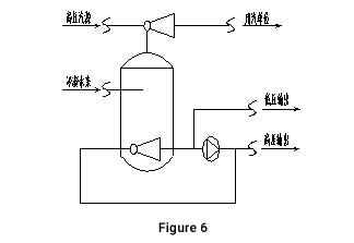
There are two recycling options, one is heating into the water, but often there is nowhere to use hot water, which is called excess entropy, which is an energy-saving problem. The other is to use high-pressure steam (such as steam above the process steam pressure or steam upstream of the pressure-reducing valve) to obtain steam after boosting, which can be used in the original process or in another process. This method of steam injection is not commonly available to manufacturers, which is the main reason why they do not recover exhaust steam.
Because the challenge of steam injection with steam lies in the design calculation of the injector, without a high-precision design software tool, the design calculation error for such very low pressure parameters will be large. We used our own developed design calculation software SSJ2. 3 and variable condition analysis software ssjoperation3. 3 to solve the problem of calculation accuracy, and also to simulate the operation of variable conditions.
We offer recovery systems with steam injection as shown in Figures 5 and 6.

4. In fact, the user site conditions are very complex, not simply to recover a condensate line, often multiple lines and a variety of pressure, different vapor content conditions at the same time, to do a better recovery program, we must analyze the site conditions, put forward personalized solutions, these unique solutions include the following measures.
1) Mutual pre-citation of water recovery before different paths. If different pressures of water are concentrated in a container to flash, then the pressure in the tank must be lower than the lowest pressure that way water pressure. This high-pressure part of the decompression is large, unnecessarily increasing the amount of flash.
2)Section recovery. According to different pressure section recovery, separately use on different occasions, so as to ensure that the high-pressure part of the degree of utilization.
Use the high-pressure section and abandon the low-pressure section. In some cases, all the conditions do not have, but if only the recycling of the higher pressure part is enough or with the use of conditions, then abandon the low-pressure part, only the high-pressure part, which will also receive great economic benefits, while the low-pressure part can be used in the future to find another way.
For the more complex site environment, it is necessary to propose a number of programs and solutions for end-users comparison, and finally selected the lowest investment and benefits of the best program.
Program Principles and Examples of Common Programs
In a process system where multiple steam pressures coexist, if the pressure difference from the original throttling and pressure reduction can be used to boost the lower steam pressure by induced injection, energy savings are inevitable. This is the principle stated in the second law of thermodynamics, and it is also the principle of our exhaust steam recovery program. For example, in the rubber tire industry, the use of new steam to draw 5 bar tank steam to obtain 8 bar steam into the process is a perfect program, it is a local measures program, which is characterized by a small amount of work, saving investment, and effective. Localized measures are a clever and wise approach, which requires familiarity with the process and is not universal. The following gives a typical program covering a more complete for reference. If the site situation does not exist or does not have the conditions, the relevant part of the system can be deleted.
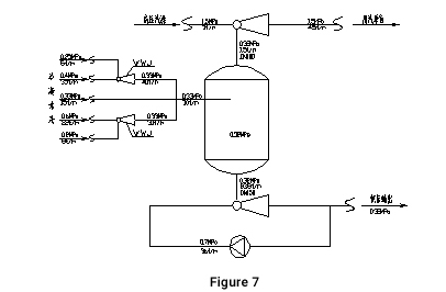
In the Figure 7 scheme, the minimum pressure of condensate is 0.2MPa, if not through the pre-priming tank pressure can not reach 0.32MPa, and it can only be lower than 0.2MPa, so it is impossible to rise to 0. 6MPa, to reach the pressure available in the process.
In this program, a small amount (36t/h) of high-pressure water is provided by the pump to draw the saturated water in the tank to raise the water by 0.03MPa and prevent cavitation of the pump.
Conclusion
Through this article, we know about condensate and steam recovery. THINKTANK, as a professional manufacturer of steam traps and control valves for condensate recovery equipment, provide professional valve selection and calculation for our customers, and if you have any questions, please feel free to contact our sales representatives.
