The critical role of the control valve in the processing system is well known. The control valve’s regular operation requires the system to provide air/electricity source and signal source. The correct provision of the air/electricity source and the signal source is the control valve’s essential operation. Due to the control valve’s critical position, the process control system is required to ensure that the air/electric source and signal source can be correctly and continuously provided to the control valve. The actual situation is that the process control system cannot guarantee 100% correct and continuous provision of the above air/electricity source and signal source (three sources for short) without any deviation. Therefore, it must take corresponding protective measures on the control valve, namely, the three source failure(air failure, power failure, signal failure) position protection measures.
There are many kinds of control methods of control valves, and accessories are various, so the three sources of failure protection measures and solutions of control valves will be different. General need to have position feedback devise for control valves if required three source failure protection measures. It means need a feedback signal to the control system, also assembly with handwheel/handle to achieve manual operation in case of failure.
According to the different requirements of three sources of failure protection, this article lists other protection solutions and analyzes various schemes to discusses with industry counterparts.
The three sources of protection schemes discussed in this article mainly include the following:
a. Eletro-Pneumatic Digital Positioner Solution(It means the control valve assembly with E/P smart positioner)
b. Eletreo-Pneumatic Analog Positioner Solution (It means the control valve assembly with E/P valve positioner)
c. Eletro-Pneumatic Converter + Pneumatic-Pneumatic Valve Positioner Solution (It means the control valve assembly with an electro-pneumatic converter and P/P valve positioner)
d. Analog Pneumatic Positioner Solution (It means the control valve assembly with P/P valve positioner)
e. Intelligent Electric Control Valve Solution
a. Eletro-Pneumatic Digital Positioner Solution
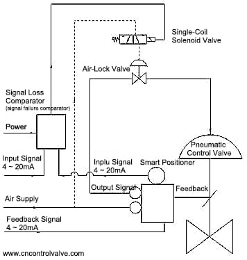
This program is mainly composed of a pneumatic control valve, intelligent electric-pneumatic valve positioner, power loss (signal) comparator, single-coil solenoid valve, air-lock valve, and so on. Its working principle is as follows:
- Air source failure: When the air supply of the control system failure (means lost air), the air-lock valve automatically closes to lock the output signal pressure of the positioner in the diaphragm chamber of the pneumatic control valve, and the output signal pressure is balanced against the reaction force generated by the control valve spring, the valve position of the pneumatic control valve remains at the fault position. The air-lock valve should be set to start slightly below the minimum value of the air supply.
- Power source failure: When the power supply of the control system fails (power loss), Loss of power (signal) comparator control the output voltage disappeared, the single-coil solenoid valve loses power, and its spool valve inner of solenoid valve slides under the action of the return spring, the solenoid valve is reversed, the pressure of the diaphragm chamber of the pneumatic retaining valve is emptied, the pneumatic retaining valve is closed, and the output signal pressure of the positioner is locked in the pneumatic control valve In the diaphragm chamber, the output signal pressure is balanced with the reaction force generated by the diaphragm spring, and the valve position of the pneumatic control valve remains at the failure position.
- Signal failure: When the control system signal is faulty (signal loss), after the power loss (signal) comparator detects it, the voltage signal of the single-coil solenoid valve is cut off. The spool valve in the solenoid directional control valve slides under the action of the return spring. The solenoid valve reverses to empty the air-lock valve pressure and closes the air-lock valve to locks the output signal pressure of the positioner in the diaphragm chamber of the control valve. The output signal pressure is balanced with the reaction force generated by the control valve spring. The valve position of the pneumatic control valve remains at the failure position.
The electric-pneumatic smart positioner gives the position feedback signal and no need for a valve position signal returner. General, the smart electric-pneumatic valve positioner itself can realize the position feedback with its own or additional position feedback module.
This solution’s advantages: relatively few accessories are used (no valve position signal returner is needed), and it takes up less space. Installation and debugging are more convenient, simple, and fast. When the “three failure” protection is activated, the system reacts quickly and acts quickly.
This solution’s weakness: the solenoid valve is charged for a long time, which affects the service life. The overall cost is relatively high, and the reliability of the accessories is relatively high.
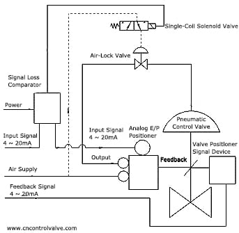
b. Eletreo-Pneumatic Analog Positioner Solution
This solution is mainly composed of a pneumatic control valve, analog electric-pneumatic valve positioner, power loss (signal) comparator, single-coil solenoid valve, pneumatic retaining valve, valve position signal returner, etc. Its working principle is the same as the smart electric-pneumatic valve positioner scheme.
The valve position signal returner gives the position feedback signal.
The advantage of this solution: When the “three sources failure” protection starts, the system reacts quickly and acts quickly. The overall cost is lower than option a.
The disadvantage of this solution: the solenoid valve is charged for a long time, affecting the service life. There are many accessories, and the installation and debugging are more complicated than the solution a. The valve position feedback needs to be equipped with a valve position signal returner. In the case of a handwheel, it is more complicated.
c. Eletro-Pneumatic Converter + Pneumatic-Pneumatic Valve Positioner Solution
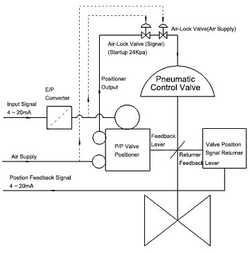
This program is mainly composed of a pneumatic control valve, analog pneumatic valve positioner, electric-pneumatic converter, air-lock valve, valve position signal returner, etc. Its working principle is as follows:
- Air source failure: When the air source of the control system fails (lost air), the pneumatic retaining valve used to control the loss of the air source is automatically closed, and the output signal pressure of the positioner is locked in the diaphragm chamber of the pneumatic control valve to output the signal pressure In balance with the reaction force generated by the control valve spring, the valve position of the pneumatic control valve remains at the fault position. The retaining valve should be set to start slightly below the minimum value of the air supply.
- Signal failure: When the control system signal fails (signal loss), the output signal pressure of the electric-pneumatic converter is synchronously lost, and the air-lock valve used for the control signal loss is automatically closed to lock the output pressure of the diaphragm chamber of the actuator, the output signal pressure is balanced with the reaction force generated by the control valve spring, and the valve position of the pneumatic control valve remains at the failure position. The air-lock valve should be set to start when it is slightly lower than the input signal’s minimum value.
- No power supply failure position of the control valve is needed.
- The valve position signal returner gives the position feedback signal.
The advantages of this solution:
- No power supply failure position of the control valve is needed.
- Only two failure valve position of a valve is required.
- It can be used on occasions with strict requirements for explosion protection.
Disadvantages of this solution: when the signal is a failure, there is a very short lag, and more accessories are used. The installation and debugging are more complicated than the solution (a). The valve position feedback needs to be equipped with a valve position signal returner. In the case of rounds, it is more complicated.
d. Analog Pneumatic Positioner Solution
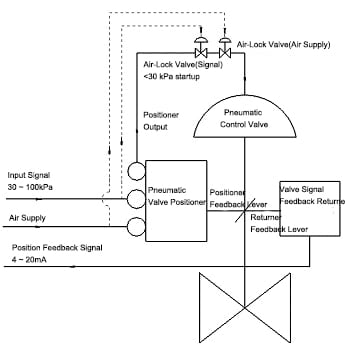
This program is mainly composed of a pneumatic control valve, analog pneumatic valve positioner, air-lock valve, valve position signal returner, etc. Its working principle is as follows:
- Air source failure: When the air source of the control system fails (lost air), the air-lock valve used to control the loss of the air source is automatically closed, and the output signal pressure of the positioner is locked in the diaphragm chamber of the pneumatic control valve, the output signal pressure is balanced with the reaction force generated by the control valve spring, and the valve position of the pneumatic control valve remains at the fault position. The air-lock valve should be set to start slightly below the minimum value of the air supply.
- Signal failure: When the control system signal fails (signal loss), the pneumatic air-lock valve used to control the signal loss is automatically closed, and the output signal pressure of the positioner is locked in the diaphragm chamber of the pneumatic control valve, and the output signal pressure and control The reaction force generated by the valve spring is balanced, and the valve position of the pneumatic control valve remains at the fault position. The air-lock valve should be set to start when it is slightly lower than the input signal’s minimum value. When the signal is failure, there is a certain lag, and the lag time is related to the pneumatic signal pipeline’s length.
The advantages of this solution:
- No power supply failure position of the control valve is needed.
- The valve position signal returner gives the position feedback signal
The advantage of this solution: It is equipped with fewer accessories, which is convenient for installation and debugging. The overall cost is low, and it can be used in occasions with exceptionally high requirements for explosion protection.
Disadvantages of this system: when the signal is failure, there is a certain lag related to the length of the signal pipeline. Valve position feedback requires an additional valve position signal returner, which is more complicated when equipped with a handwheel. Only suitable for pneumatic signal occasions.
e. Intelligent Electric Control Valve Solution
The intelligent electric control valve is composed of a smart electric actuator and a valve. The intelligent electric actuator itself has the function of power-off and position retention. When the signal is interrupted, it can select the functions of keeping the original position, fully closed and fully open. And it has a signal feedback function. So it has a wide application range.
The advantage of this solution: No need to connect to the air source, only two failure protection can be realized, with less installation space. Installation and debugging are more convenient, simple and fast. When the “two breaks” protection is activated, the system reacts quickly and acts quickly. The valve itself has a signal feedback function, and there is no need to install a valve position signal returner.
Disadvantages of this system: the overall cost is relatively high, and the use is limited in occasions where explosion-proof requirements are particularly strict.
The above solution is the most basic scheme of the three-break protection scheme, and during the three-break, the valve remains in the original position (hold position).
If you need other protection methods, you can change the above scheme.
The following introduces a protection scheme in which the double-acting valve fully opens or fully closed when the air source fails (loss of air).
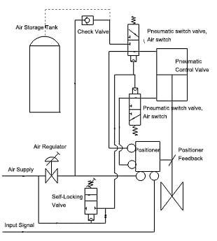
This program is mainly composed of control valves, pneumatic reversing valves, positioners, self-locking valves, check valves/non-return valve, air regulator, gas storage tanks, etc. Its working principle is as follows:
When the air source of the control system fails (lose air), the self-locking valve (the function of which is opposite to that of the retaining valve) will automatically open to cancel the air source of the air-controlled directional valve. The slide valve of the air-controlled directional valve is reset under the action of spring, one of the air-controlled reversing valves is exhausted, the other is aired, and the non-return valve is closed. The air source is supplied to the valve from the gas storage tank, to realize the valve fully closed or open. It can recognize a fully closed or fully open by adjusting the pneumatic control valve’s connection mode.
If you want to realize valve retention, install a pneumatic retention valve, change the pipeline connection, use a self-locking valve to control the air-lock valve directly, and cancel the pneumatic control reversing valve, check valve and gas tank.
If you want to ensure that the valve has several actions when the air source is failed, the following solutions can be used.
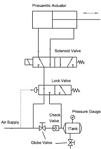
This scheme consists of a gas storage tank, a check valve, a blocking valve, a globe valve, etc. Its working principle is as follows:
When the air supply fails (loss of air), the check valve is closed, the lock valve loses air, the slide valve of the lock valve is reset under the action of the spring, the air circuit is reversed, the air source pipeline of the system is disconnected, and the gas storage tank supplies gas to the valve to ensure that the valve has several actions to achieve the purpose of continuous control. Due to the gas storage tank’s limited capacity, and the pressure of the air supply in the gas storage tank continues to decrease with the valve action, the gas storage tank cannot be used for a long time to supply air to the valve. The capacity of the gas storage tank for this plan should be larger than that of the general protection gas storage tank. In this system, when the air supply fails, the number of valve actions is related to the gas storage tank’s capacity.
The several protection schemes listed above are just a few primary forms. To achieve different protection purposes, the above schemes can be appropriately modified. Since the documented system has its own advantages and disadvantages, a different method can be according to specific conditions of the site. For the three-break protection, when the budget is possible, combining various factors, the author recommends the plan (a) and plan (e).
