Description
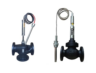
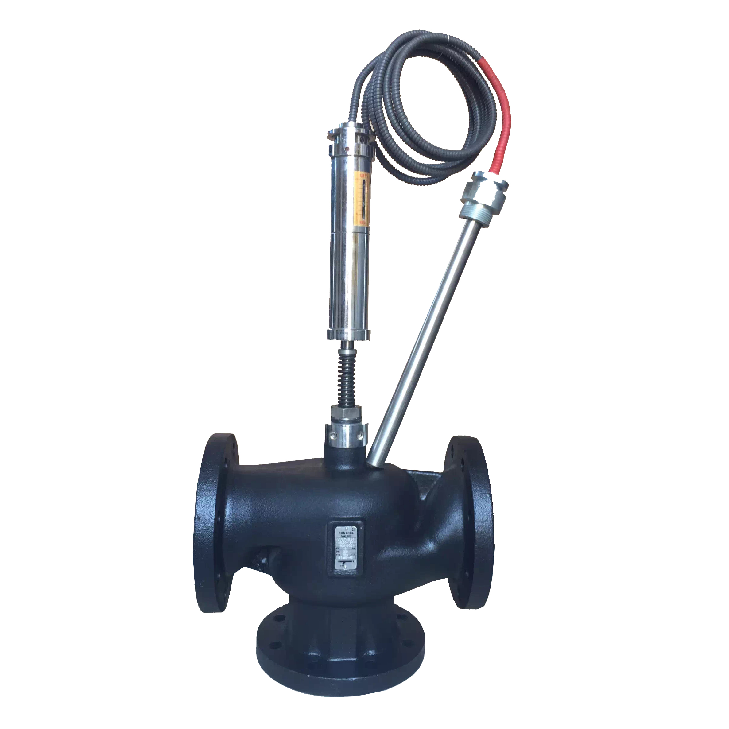
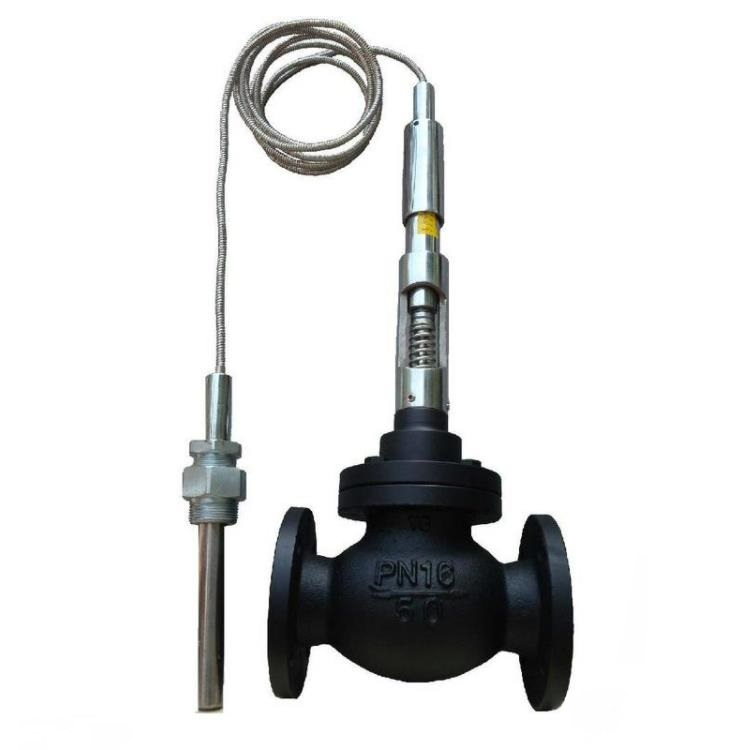
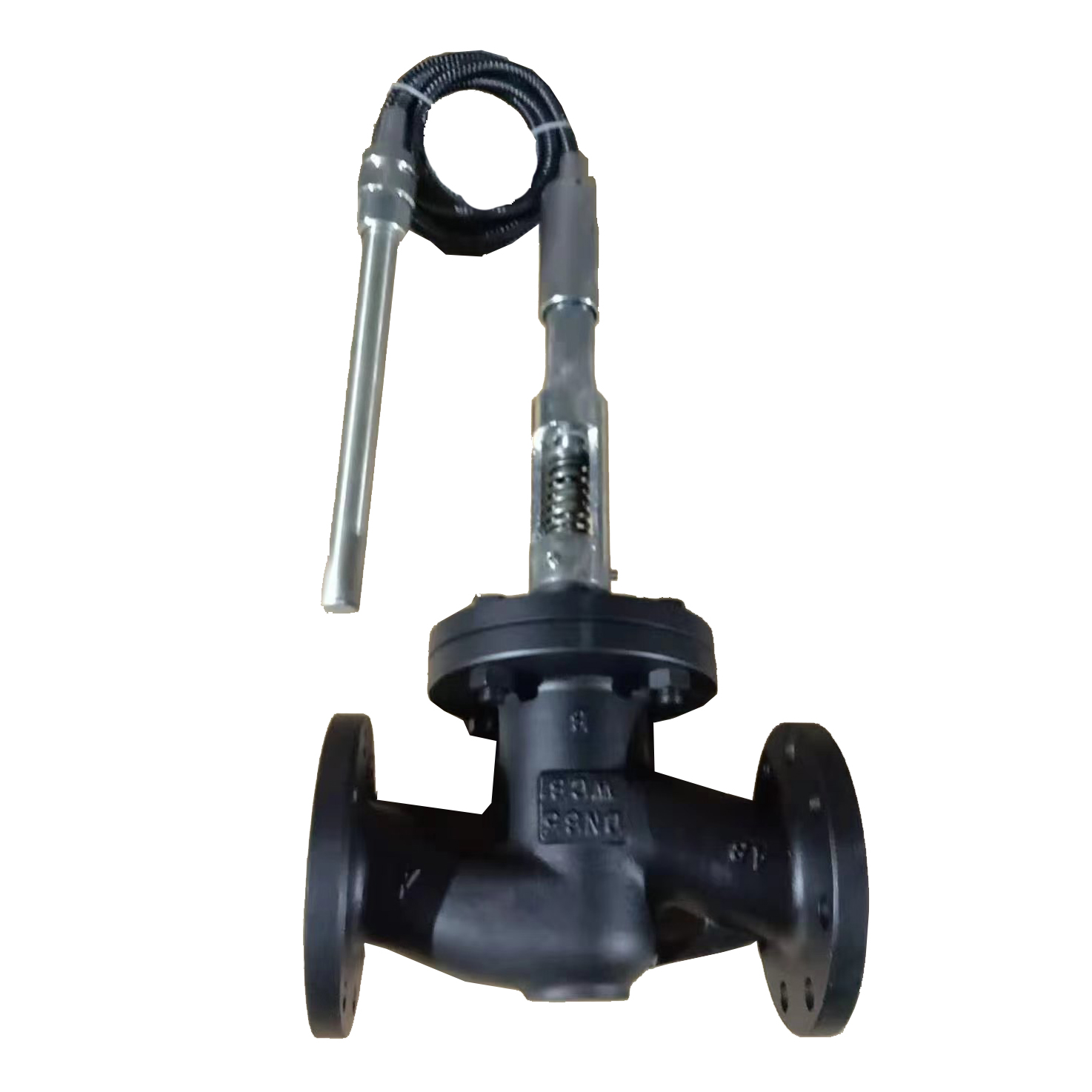
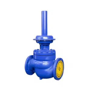
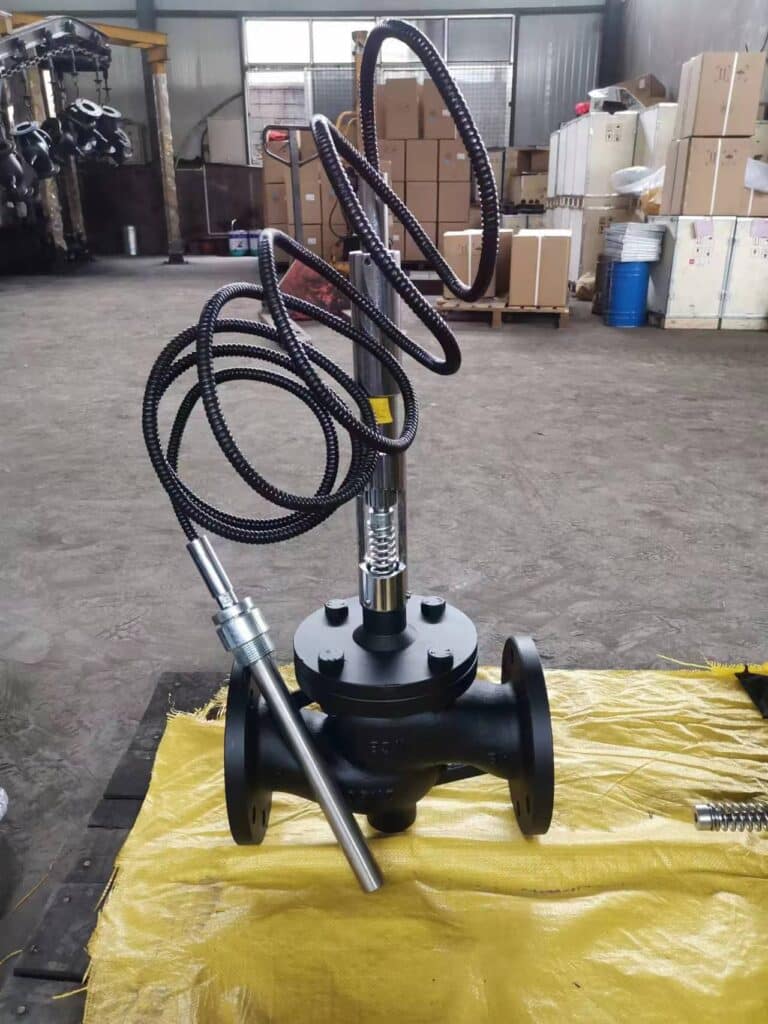
SOTR Series Self-operated temperature regulators use the principle of thermal expansion of liquid and incompressible liquid to achieve automatic adjustment without an auxiliary actuator. The expansion of the liquid in the temperature sensor is uniform. The self-operated temperature control valve controls the temperature of the medium by expanding or contracting the volume of the temperature-sensitive liquid in the sensor, thus controlling the valve opening. When the temperature of the controlled medium is higher than the set value, the temperature-sensitive liquid expands. Push the spool down to close the self-operated temperature control valve, and reduce the flow of thermal media. When the controlled medium temperature is lower than the set value, the temperature-sensitive liquid contraction. The reset spring pushes the spool to open, increasing the flow of the thermal medium. The self-operated temperature control valve is mainly used in heating and air conditioning domestic hot water, petrochemical, electric power, electromechanical textile, rubber, food, and other industries.
Features
1. Small size, lightweight, and easy to install.
2. Accurate and reliable long life.
3. Easy to adjust the setting
4. No need for auxiliary power
Working Principle
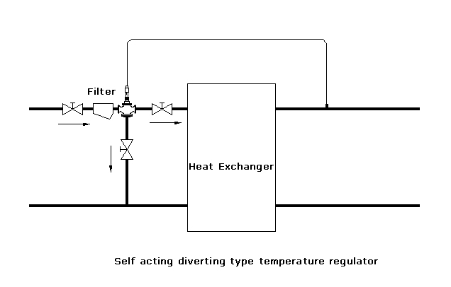
SOTR self-operated temperature control valve can be divided into heating temperature control valve, cooling temperature control valve, three-way mixing type temperature control valve, and three-way dividing type temperature control valve. Different purposes of the self-operated temperature control valve working principle are similar, are the use of temperature-sensitive liquid expansion by heat, cold contraction, and the incompressible liquid principle of adjustment.
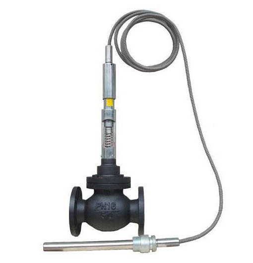
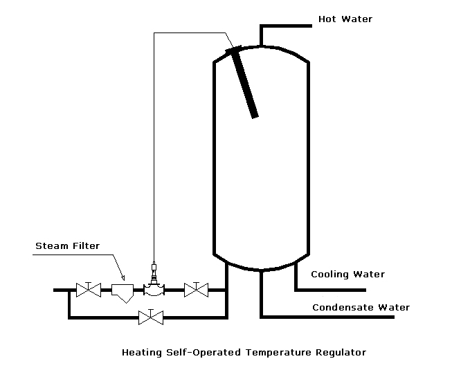
We use the heating temperature control valve as an example: the temperature sensor into the controlled medium, when the controlled medium temperature rises, the temperature-sensitive liquid expansion, the force to overcome the spring resistance, push the plug downward, and the valve tends to close, thereby reducing the flow of thermal media; Conversely when the controlled medium temperature is lower than the set value, the temperature-sensitive liquid contraction, spring reset to push the plug open, increase the flow of thermal media so that the controlled media temperature tends to rise. Cycle repeatedly, so that the temperature of the controlled medium is always maintained within the allowable range of the set temperature value.
Performance
| Size DN | 20 | 25 | 32 | 40 | 50 | 65 | 80 | 100 | 125 | 150 | 200 | 250 |
| Kv Value (m3/h) | 3.4 | 5.5 | 11 | 15 | 19 | 31 | 52 | 78 | 122 | 190 | 300 | 350 |
| Nominal Pressure | PN1.6, 2.5MPa | |||||||||||
| Flange Standard | GB/T9113、 JB/T79、HG20594 or others | |||||||||||
| Body Material | Cast Iron, Cast Steel, Stainless Steel | |||||||||||
| Trim Material | Stainless Steel | |||||||||||
| Sensor Material | Brass /Nickel Brass | |||||||||||
| Set Temperature Deviation | ±2℃ | |||||||||||
| Temperature Range | For Hot Water: 30~100℃. For Heating and Air Conditioning: 40~90℃; For Deaerator and other Business Processes: 80~110℃. For other special Purposes: 120~180℃ |
|||||||||||
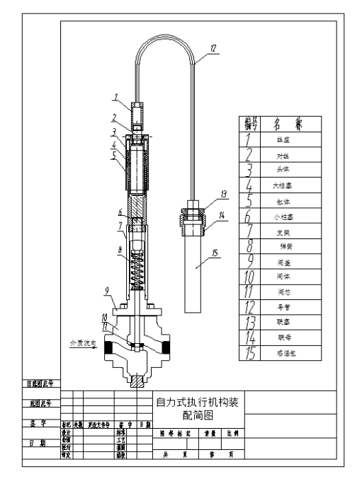
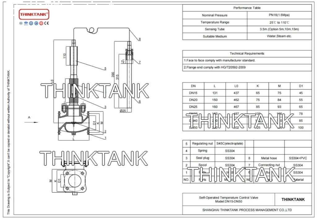
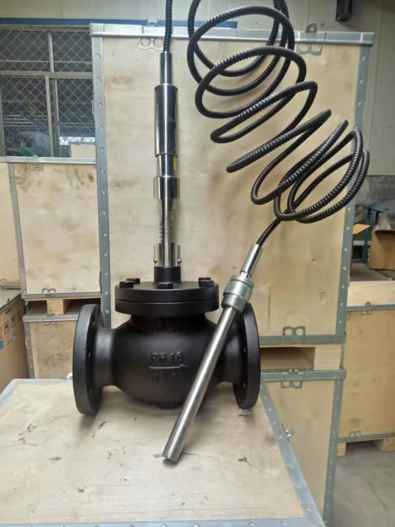
Self-Operated Temperature Regulator Drawing
How to Install and Use Self-Operated Temperature Regulators
1. In order to avoid damage to the product in transportation, the control part of the temperature control valve and the valve body part are packed separately, and the factory number of the two must be the same when installed.
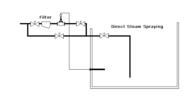
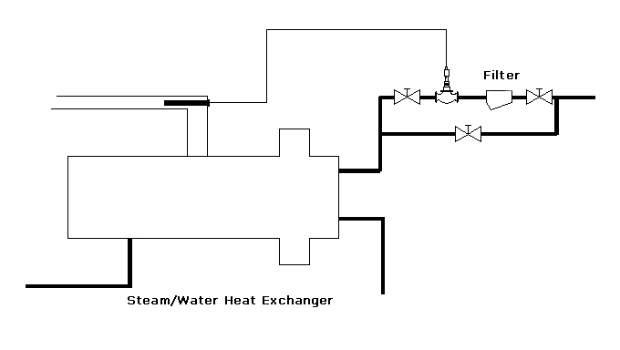
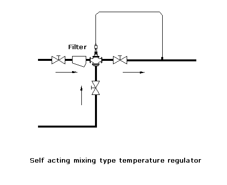
2. The valve should be cleaned before installation of the pipeline, there should be no debris. The valve body installation actuator must be perpendicular to the ground, the valve body inlet direction, and the direction of flow of the thermal medium. This temperature control valve should be installed before and after the shut-off valve, and the control valve should be installed before the filter to avoid impurities damaging the sealing surface. In order to facilitate the use of the user and the maintenance of the temperature regulator, a bypass pipeline should be set and a shut-off valve should be installed, please refer to the schematic diagram.
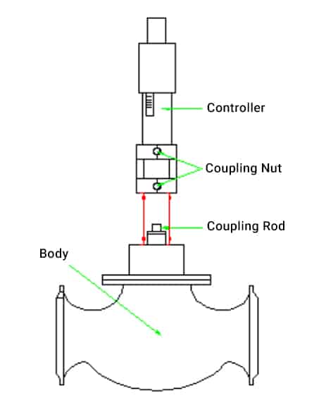
3. Loosen the fixing nut and remove the protection sleeve before installing the controller.
4. Install the controller vertically on the ground or horizontally.
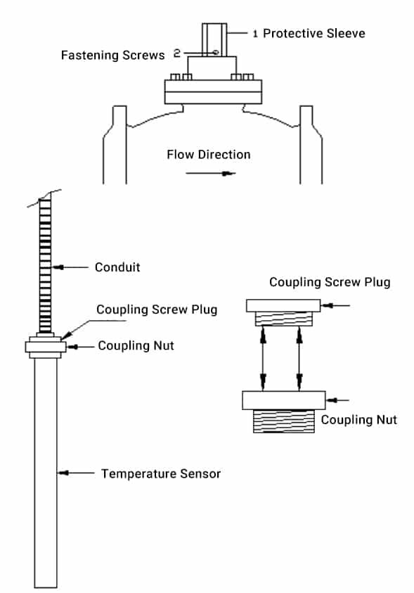
5. Place the controller on the valve body and fasten the set screw with a (4mm) 1 protective sleeve, and 2 fastening screws for fixing screws hexagonal plate hand.
6. Before installing the temperature sensor, expand the conduit along the spiral direction, and forbid hard pulling to avoid breaking the conduit. When the conduit needs to be bent, the minimum bending radius of 60mm installation, first remove the sensor coupling nut and installed it in the heat exchanger or outlet pipe, the lower side of the convex side of the upper end of the sensor wrapped asbestos rope into the sensor coupling nut, tighten the sensor coupling screw plug. During the tightening process, the sensor should not be rotated to avoid damage to the conduit. The temperature sensor should be completely submerged in the heated medium, do not install the sensor in the sleeve. A thermometer or other temperature display device should be installed near the sensor to observe temperature changes.
7. As a professional control valve factory, THINKTANK generally has been finished set according to user requirements for temperature, the user only needs to fine-tune when using. Fine adjustment or change of the set temperature method is as follows: insert the adjusting wrench into the adjusting hole of the temperature setting knob, and turn the adjusting wrench counterclockwise when adjusting from low to high temperature; when adjusting from high to low temperature, wait until the sensor temperature cools to the adjusted temperature, and turn the adjusting wrench clockwise.
8. Attention.
(1) The temperature control valve can not be used as a shut-off valve, when the system stops heating, the thermal media shut-off valve should be closed.
(2) when using, should carefully check the conduit, if the conduit fracture liquid leakage, or odor overflow, should stop using.
(3) When the temperature of the heated medium is low, refer to Article 7, and adjust to the high temperature, if not effective, open the bypass, if the temperature is still low, it is the heat source or system problem.
(4) When the heated medium temperature is high, refer to Article 7, and adjust to a low temperature, if invalid, check the bypass for air leakage.
(5) The regulating valve is a precision instrument, private disassembly is strictly prohibited, if there is a problem, please contact the agent or our company.
Installation Schematic Diagram
Note: A filter must be installed upstream of the valve and the actuator must be mounted vertically to the ground (as shown in the figure). It is not allowed to be used as a shut-off valve.
(1) A filter must be installed in front of the valve.
(2) Over-temperature and over-pressure are strictly prohibited.
(3) Use as a shut-off valve is strictly prohibited.
(4) Must be installed vertically.
Dimensions
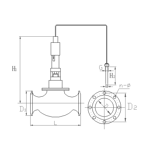
| Size | H1
(mm) |
D1
(mm) |
D
(mm) |
D2
(mm) |
L
(mm) |
d
(mm) |
G
(mm) |
H2
(mm) |
n-Φ
(mm) |
Weight (kg) |
| DN32 | 555 | 135 | 32 | 100 | 180 | 25 | 1-1/4 | 180 | 4-Φ18 | 23 |
| DN40 | 570 | 145 | 40 | 110 | 200 | 25 | 1-1/4 | 180 | 4-Φ18 | 25 |
| DN50 | 610 | 160 | 50 | 125 | 230 | 25 | 1-1/4 | 280 | 4-Φ18 | 28 |
| DN65 | 635 | 180 | 65 | 145 | 290 | 25 | 1-1/4 | 280 | 4-Φ18 | 33 |
| DN80 | 680 | 195 | 80 | 160 | 310 | 25 | 1-1/4 | 280 | 8-Φ18 | 45 |
| DN100 | 720 | 215 | 100 | 180 | 350 | 25 | 1-1/4 | 280 | 8-Φ18 | 57 |
| DN125 | 760 | 245 | 125 | 210 | 395 | 25 | 1-1/4 | 380 | 8-Φ18 | 73 |
| DN150 | 800 | 280 | 150 | 240 | 470 | 25 | 1-1/4 | 380 | 8-Φ23 | 100 |
| DN200 | 950 | 335 | 200 | 300 | 550 | 25 | 1-1/4 | 480 | 12-Φ22 | 200 |
| DN250 | 985 | 405 | 250 | 355 | 640 | 25 | 1-1/4 | 480 | 12-Φ22 | 250 |
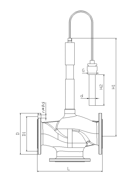
| Size | ΦD | ΦD | ΦD1 | ΦD1 | n-Φd | n-Φd | L | H1 | G | d | H2 |
| mm | PN16 | PN25 | PN16 | PN25 | PN16 | PN25 | mm | mm | mm | mm | mm |
| DN15 | Φ95 | Φ95 | Φ65 | Φ65 | 4 x Φ14 | 4 x Φ14 | 130 | 466 | 11/4 | 25 | 280 |
| DN20 | Φ105 | Φ105 | Φ75 | Φ75 | 4 x Φ14 | 4 x Φ14 | 140 | 470 | 11/4 | 25 | 280 |
| DN25 | Φ115 | Φ115 | Φ85 | Φ85 | 4 x Φ14 | 4 x Φ14 | 165 | 470 | 11/4 | 25 | 280 |
| DN32 | Φ140 | Φ140 | Φ100 | Φ100 | 4 x Φ18 | 4 x Φ18 | 180 | 474 | 11/4 | 25 | 280 |
| DN40 | Φ150 | Φ150 | Φ110 | Φ110 | 4 x Φ18 | 4 x Φ18 | 200 | 469 | 11/4 | 25 | 280 |
| DN50 | Φ165 | Φ165 | Φ125 | Φ125 | 4 x Φ18 | 4 x Φ18 | 230 | 499 | 11/4 | 25 | 280 |
| DN65 | Φ185 | Φ185 | Φ145 | Φ145 | 4 x Φ18 | 8 x Φ18 | 290 | 515 | 11/4 | 25 | 280 |
| DN80 | Φ200 | Φ200 | Φ160 | Φ160 | 8 x Φ18 | 8 x Φ18 | 310 | 518 | 11/4 | 25 | 280 |
| DN100 | Φ220 | Φ235 | Φ180 | Φ190 | 8 x Φ18 | 8 x Φ22 | 350 | 538 | 11/4 | 25 | 280 |
| DN125 | Φ250 | Φ270 | Φ210 | Φ220 | 8 x Φ18 | 8 x Φ26 | 400 | 565 | 11/4 | 25 | 380 |
| DN150 | Φ285 | Φ300 | Φ240 | Φ250 | 8 x Φ22 | 8 x Φ26 | 480 | 581 | 11/4 | 25 | 380 |
