


Description
- Drain valve used for main steam piping and reheater steam
- Medium: Saturated water, e.g. Main steam drain valve, Auxiliary steam drain valve
- Forged steel body: F91, F92, 12Cr1MoV, 20#
- Configuration: straight through
- Connections: welded, or flanges
- Cavitation free design, shut off tightly for many years
- Compact valve body, easy installation
- Throttling stages: 2, unbalanced trim
- Leakage Class: ANSI V
- Size: DN20-DN80
- Pressure: 42Mpa

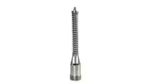
State 1: A cylindrical throttle plug is arranged at the lower end of the sealing surface of the valve plug. When the valve plug is fully closed and there is no leakage, the throttle plug has almost no effect. When the valve port is not tightly sealed and there is leakage, the throttle plug will block the flow to prevent the leakage flow from further increasing and prevent the valve port from being further washed.
State 2: When the valve plug is opened, the throttle plug stops the flow until the throttle plug leaves the valve seat, the medium flow is very small, and there is no scouring of the valve port.
State 3: When the throttle plug is completely separated from the seat port, the flow of the medium increases. Because the sealing surface of the valve seat is on the outermost side of the flow channel, so flow rate here is much slower than that of the flow-through, and the erosion of the valve seat is also small.

| 32 | Reducer | 20# | 12Cr1MoV | F91 | F92 |
| 27 | Packing Block | OCr18Ni9 | OCr18Ni9 | OCr18Ni9 | OCr17Ni12Mo2 |
| 26 | Pin | 1Cr18Ni9Ti | 1Cr18Ni9Ti | 1Cr18Ni9Ti | 1Cr18Ni9Ti |
| 25 | Packing | Graphite | Graphite | Graphite | Graphite |
| 23 | Nuts | 35# | 35CrMoA | 35CrMoA | 25Cr2MoV |
| 22 | Plate Bolts | 35CrMoA | 25Cr2MoV | 25Cr2MoV | 25Cr2Mo1V |
| 14 | Positioning Splint | 45# | 45# | 45# | 45# |
| 12 | Packing Plate | 45# | 45# | 45# | 45# |
| 11 | Packing Gland | 0Cr18Ni9 | 0Cr18Ni9 | 0Cr18Ni9 | 0Cr18Ni9 |
| 10 | Nuts | 20# | 20# | 15CrMo | 12Cr1MoV |
| 9 | Top Flange | 20# | 20# | 20# | 15CrMo |
| 6 | Stem | High chromium heat resistant stainless steel (Seat Hardfacing STL) |
High chromium heat resistant stainless steel (Seat Hardfacing STL) |
High chromium heat resistant stainless steel (Seat Hardfacing STL) |
High chromium heat resistant stainless steel (Seat Hardfacing STL) |
| 1 | Body | 20# (Hardfacing Steilise) |
12Cr1MoV (Hardfacing Steilise) |
F91 (Hardfacing Steilise) |
F92 (Hardfacing Steilise) |
| Item | Parts Name | 20# | 12Cr1MoV | F91 | F92 |

| DN(mm) | Dimensions (mm) | Kv (m3/h) |
Weight (Kg) | |||||
| L | H | H1 | A | B | Stroke T | |||
| 20 | 340 | 390 | 72 | 200 | 110 | 25 | 12 | 35 |
| 25 | 340 | 390 | 72 | 200 | 110 | 25 | 12 | 35 |
| 32 | 340 | 390 | 72 | 200 | 110 | 25 | 12 | 35 |
| 40 | 340 | 390 | 72 | 200 | 110 | 25 | 12 | 35 |
| 50 | 380 | 390 | 72 | 200 | 110 | 25 | 16 | 38 |
| 65 | 380 | 390 | 72 | 200 | 110 | 25 | 16 | 38 |
| 80 | 400 | 390 | 72 | 200 | 110 | 30 | 25 | 42 |

| DN(mm) | Dimensions (mm) | Kv (m3/h) |
Weight (Kg)
Without Actuator |
|||||||||||
| L | H | H1 | A | A1 | A2 | A3 | A4 | A5 | B | B1 | Stroke T | |||
| 20 | 340 | 355 | 72 | 590 | 371 | 320 | 581 | 370 | 365 | 110 | 168 | 25 | 12 | 33 |
| 25 | 340 | 355 | 72 | 590 | 371 | 320 | 581 | 370 | 365 | 110 | 168 | 25 | 12 | 33 |
| 32 | 340 | 355 | 72 | 590 | 371 | 320 | 581 | 370 | 365 | 110 | 168 | 25 | 12 | 33 |
| 40 | 340 | 355 | 72 | 590 | 371 | 320 | 581 | 370 | 365 | 110 | 168 | 25 | 12 | 33 |
| 50 | 380 | 355 | 72 | 590 | 371 | 320 | 581 | 370 | 365 | 110 | 168 | 25 | 16 | 35 |
| 65 | 380 | 355 | 72 | 590 | 371 | 320 | 581 | 370 | 365 | 110 | 168 | 25 | 16 | 38 |
| 80 | 400 | 355 | 72 | 590 | 371 | 320 | 581 | 370 | 365 | 110 | 168 | 30 | 25 | 42 |

PN≤16MPa
| DN(mm) | Dimensions (mm) | Kv (m3/h) |
Weight (Kg) Without Actuator |
||||||
| L | H | H1 | A | A1 | B | Stroke T | |||
| 20 | 340 | 580 | 72 | 250 | 220×220 | 110 | 25 | 12 | 58 |
| 25 | 340 | 580 | 72 | 250 | 220×220 | 110 | 25 | 12 | 58 |
| 32 | 340 | 580 | 72 | 250 | 220×220 | 110 | 25 | 12 | 58 |
| 40 | 340 | 580 | 72 | 250 | 220×220 | 110 | 25 | 12 | 58 |
| 50 | 380 | 580 | 72 | 250 | 220×220 | 110 | 25 | 12 | 60 |
| 65 | 380 | 580 | 72 | 250 | 220×220 | 110 | 25 | 16 | 62 |
| 80 | 400 | 780 | 72 | 350 | 390 | 110 | 30 | 25 | 105 |
PN≥25MPa
| DN(mm) | Dimensions (mm) | Kv (m3/h) |
Weight (Kg) Without Actuator |
||||||
| L | H | H1 | A | A1 | B | Stroke T | |||
| 20 | 340 | 630 | 72 | 350 | 340 | 110 | 25 | 12 | 80 |
| 25 | 340 | 630 | 72 | 350 | 340 | 110 | 25 | 12 | 80 |
| 32 | 340 | 630 | 72 | 350 | 340 | 110 | 25 | 12 | 80 |
| 40 | 340 | 630 | 72 | 350 | 340 | 110 | 25 | 12 | 80 |
| 50 | 380 | 630 | 72 | 350 | 340 | 110 | 25 | 12 | 82 |
| 65 | 380 | 630 | 72 | 350 | 340 | 110 | 25 | 16 | 85 |
| 80 | 400 | 780 | 72 | 350 | 390 | 110 | 30 | 25 | 105 |