Selection Methods and Skills of Electric Actuators
As the most important control element in the industrial process-control valves, it is driving commonly used in electric and pneumatic types. The electric control valve simply says just a control valve body assembly with an electric actuator. There are many types and functions of electric actuators. In the process of design and selection, usually, only valve parameters are emphasized, but the relevant requirements of electric actuators are ignored or not clear. So if not pay attention to actuator requirements, debugging, use processes will also bring unnecessary trouble.
I. Briefly introduce several electric actuators that can be matched with the control valve.
1. Rotary type electric actuator (rotation angle <360 degrees);
The rotation of the output shaft of the electric actuator is less than one circle, that is, less than 360 degrees, usually 90 degrees to achieve the valve opening and closing process control.
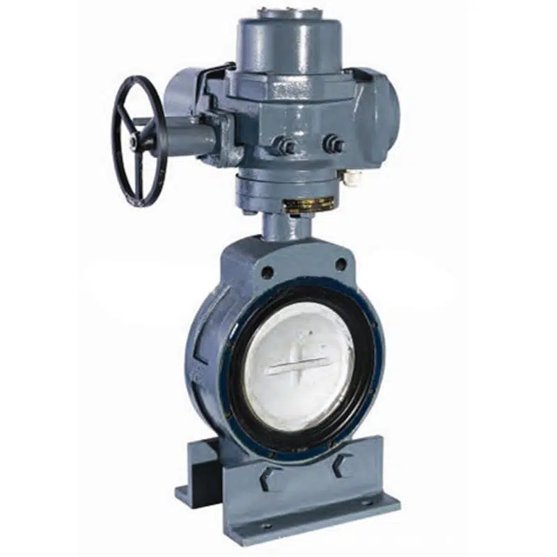
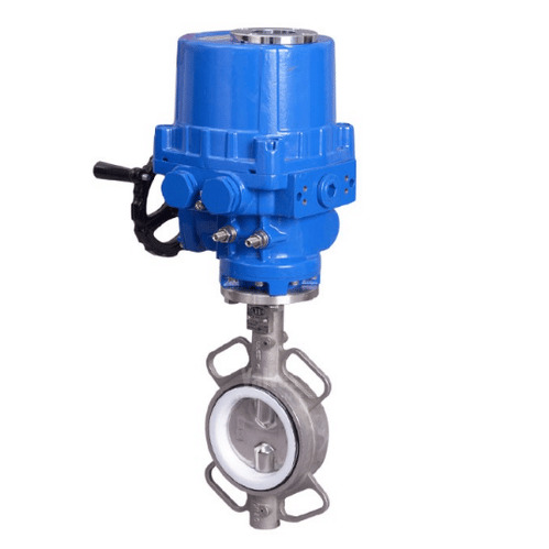
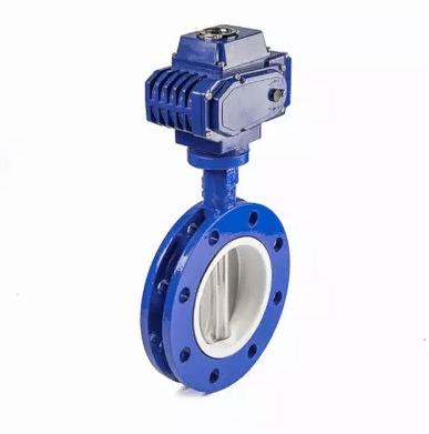
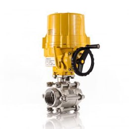
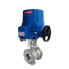
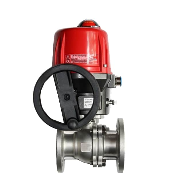
This type of electric actuator is divided into two types: direct connection type and base crank type according to the different installation methods.
a) Direct connection type: refers to the form in which the output shaft of the electric actuator is directly connected to the valve stem.
b) Base crank type: refers to the form in which the output shaft is connected to the valve stem through a crank. This type of electric actuator is suitable for butterfly valves, ball valves, plug valves, etc.
2. Multi-turn electric actuators (angle of rotation>360 degrees);
This type of electric actuator is suitable for gate valves, globe valves, etc.
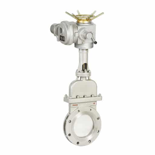
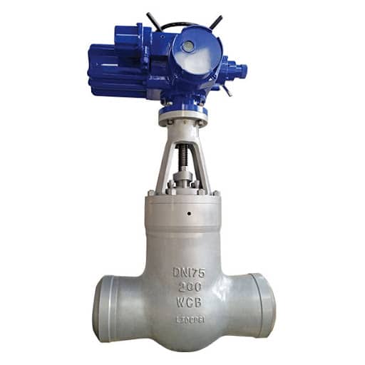
3. Linear type electric actuator (linear motion);
This type of electric actuator is suitable for single-seat control valves, double-seat control valves, etc.
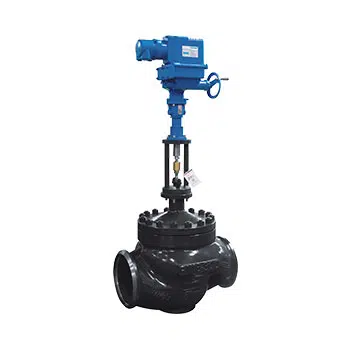
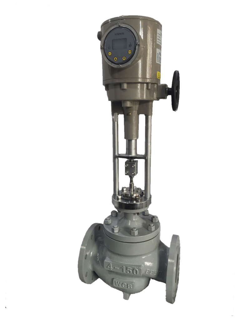
II. Select electric actuators according to the production process control requirements of valve electric actuators
The control modes of electric actuators are generally divided into two categories: On/off type (open-loop control) and regulating/modulating type (closed-loop control).
On/off type (open loop control)
On/off type electric actuators generally realize the full opening or closing control of the valve. The valve is in the fully open or fully closed position. This type of valve does not require precise control of the medium flow rate. For on/off type electric actuators can be divided into split structure and integrated structure due to different structural. This must be explained when selecting the model, otherwise mismatches such as conflicts with the control system during on-site installation will often occur.
a) Split structure (usually called ordinary type):
The control unit is separated from the electric actuator. The electric actuator cannot control the valve alone. It must be controlled by an external control unit. The disadvantage of this structure is that it is inconvenient for the overall installation of the system, increases the cost of the level transmitter, wiring, and installation, and is prone to failure. When a failure occurs, it is not easy to diagnose and repair, and the cost performance is not ideal.
b) Integrated structure (usually called integral type):
The control unit and the electric actuator are packaged as one, and can be operated on the spot without external control unit, and can be operated remotely only by outputting relevant control information. The advantage of this structure is that it facilitates the overall installation of the system, reduces wiring and installation costs, and is easy to diagnose and troubleshoot.
Regulating type (closed loop control)
Regulating electric actuators not only have a switch-type integrated structure but also precisely adjust the medium flow, it can also accurately control the valve. The following is a brief description of the parameters that need to be noted when selecting the adjustable electric actuator.
a) Control signal type (current, voltage)
The control signal of the regulating electric actuator generally includes current signal (4~20mA, 0~10mA) or voltage signal (0~5V, 1~5V), which should be clarified when selecting the signal type and parameters.
b) Working type(opening type, closing type)
The working mode of the regulating electric actuator is generally opening type (taking 4-20mA control signal as an example, opening type means that 4mA signal corresponds to valve closing, 20mA Corresponds to valve opening), and the other is closing type (means that 4mA signal corresponds to valve opening, and 20mA corresponds to valve closing).
c) Loss of signal protection
Loss of signal protection means that when the control signal is lost due to cable faults, the electric actuator will open and close the control valve to the set protection value. The common protection values have three situations, fully open, fully closed, or keep the last position. The intelligent electric actuator can be flexibly modified through on-site settings, and any position (0~100%) can be set as the protection value.
III. Choose the electric valve actuator according to the valve operating torque
The torque required for the normal opening and closing of the valve is determined by factors such as valve diameter, working pressure, etc. However, the processing accuracy and assembly process of different valve manufacturers are different, so the torque required for the same specification valve is also different. When selecting the type of actuator, if the torque of the actuator is too small, the valve cannot be opened and closed normally. Therefore, the electric actuator must select a reasonable torque range. The output torque of the electric actuator should be 1.2 to 1.5 times the maximum torque of the valve operation.
IV. Electrical parameters of electric actuators
Due to the differences in electrical parameters of different actuator manufacturers, it is generally necessary to determine their electrical parameters during design and selection, mainly including motor power, rated current, and secondary control loop voltage.
The most important parameter of electric actuators is the output force.
For linear electric actuators, the unit is N or Kg, 10N = 1Kg, which is called thrust. For rotary type electric actuators, The unit is Nm or Kg.m, 10Nm=1Kgm.
When selecting the output force, it should be determined according to the maximum driving force of the control valves. Generally, the actuator is required to retain 30% of the margin to be safe. Because the calculation of the driving force of the valve is very complicated, the following gives some empirical data of common valves:
Electric Actuator Torque for Gate Valves (DN25~DN1800, Pressure Rating 1~320Kg/cm2, 0.1~32MPa,Toque Unit: Kg.m)

Electric Actuator Torque for Globe Valves (DN15~DN350, Pressure Rating 6~320Kg/cm2, 0.6~32MPa, Toque Unit: Kg.m)

Electric Actuator Torque for Ball Valves (DN50~DN1000, Pressure Rating 6~100Kg/cm2, 0.6~10MPa, Toque Unit: Kg.m)

Electric Actuator Torque for Butterfly Valves (DN50~DN2000, Pressure Rating 2.5~25Kg/cm2, 0.25~2.5MPa, Toque Unit: Kg.m)


