In the world of advanced energy systems, molten salt valves are a critical component for controlling high-temperature fluids that are important for storing and transferring energy. Understanding how they’re designed, how they work, and where they’re used can be a huge help to engineers and procurement people in the fluid control and energy industries.

Molten salt valves are special valves designed to handle high temperatures and corrosive molten salts. They’re commonly used in concentrated solar power (CSP) plants and other industrial applications that involve heat transfer fluids. These valves have to be designed to prevent salt solidification, provide thermal insulation, and use materials that can handle high temperatures and corrosion.
In this article, we will introduce the details of molten salt valve technology and it features and benefits in the energy industry.
Why Choose Molten Salt Technology: Revolutionizing Clean Energy and Thermal Energy Storage
Concentrated Solar Power (CSP) plants operate by concentrating solar energy to heat a thermal fluid, which then drives a steam turbine to generate electricity. The thermal energy storage system’s efficiency hinges on the choice of heat transfer fluid. While thermal oil and steam can serve as heat transfer fluids, molten salt offers distinct advantages.
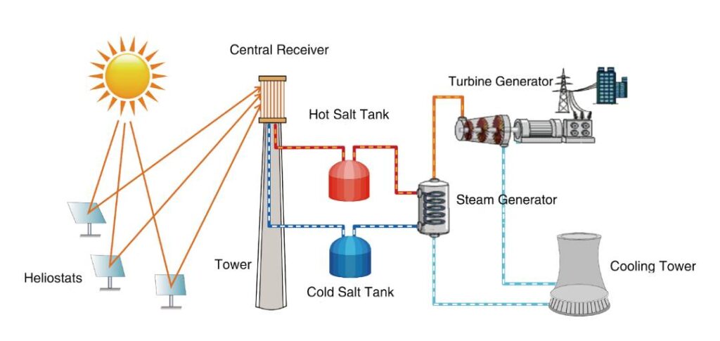
Advantages of Molten Salt in CSP Systems
Higher Operating Temperatures: Molten salt systems can operate at temperatures 140-170°C higher than thermal oil systems. This increased temperature range allows for more efficient heat transfer and storage.
Improved Power Plant Efficiency: Higher temperature steam parameters enabled by molten salt can boost power plant efficiency by approximately 4%. This translates to a 15% increase in annual power generation, providing significant economic benefits.
Enhanced Energy Storage: Molten salt’s superior thermal properties make it an excellent medium for energy storage. It allows CSP plants to store excess thermal energy during the day and release it during periods of low sunlight, ensuring a continuous power supply.
Cost-Effective Operation: Although the initial setup for molten salt technology may be higher, the long-term benefits, including higher efficiency and increased power output, result in greater overall cost-effectiveness.
Proven Reliability: Practical applications have shown that low-melting-point molten salts are increasingly becoming the preferred choice for many CSP companies. Their reliability and efficiency make them suitable for large-scale solar power projects.
Practical Applications
Heat Transfer and Storage: Molten salt’s ability to store heat at high temperatures allows CSP plants to extend their power generation capabilities beyond daylight hours.
Increased Efficiency: By operating at higher temperatures, CSP plants using molten salt can achieve greater efficiency in converting thermal energy to electrical energy.
Economic Benefits: The enhanced efficiency and higher annual power output result in considerable economic benefits, making molten salt technology a viable option for large-scale clean energy production.
What is Molten Salt?
Molten salt is the liquid state of inorganic salts. At high temperatures, these salts melt into ionic liquids that have properties like high thermal stability, low vapor pressure, and excellent heat capacity. The most common molten salt mixture used in CSP plants is a eutectic blend of 60% sodium nitrate and 40% potassium nitrate. This mixture stays liquid between 265°C and 565°C.
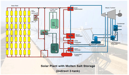
Principle of Molten Salt Heating
The idea behind molten salt heating is to heat the salt at night using low-cost electricity, store the heat in high-temperature tanks, and then use the stored heat during the day for heating. This system is very efficient at converting low-cost nighttime electricity into usable heat energy for daytime heating applications.
Molten salts are often used in concentrated solar power (CSP) plants to store thermal energy with very minimal energy loss for electricity generation. They are also used as heat transfer fluids to generate electricity through turbines.
Types of Molten Salt Valves in Solar Thermal Power Generation
Using molten salt as a thermal energy storage and transfer medium in solar thermal power generation presents unique challenges due to its high freezing point and strong corrosive nature. Traditional valve technologies struggle to adapt to these characteristics. The commonly used binary salt mixture (60% NaNO3 + 40% KNO3) in solar thermal power systems has a melting point of 220°C and remains in a liquid state above 260°C, with strong oxidizing properties. The operating temperature typically ranges from 390°C to 575°C, with a design temperature around 600°C. The high temperature and strong oxidizing environment cause conventional valve sealing materials to oxidize, lose weight, and relax, resulting in serious leakage. Therefore, switch and control valves are essential in the process pipelines of heat absorption towers and cold/hot molten salt storage tanks to manage the heat transfer and storage processes in solar thermal power plants.
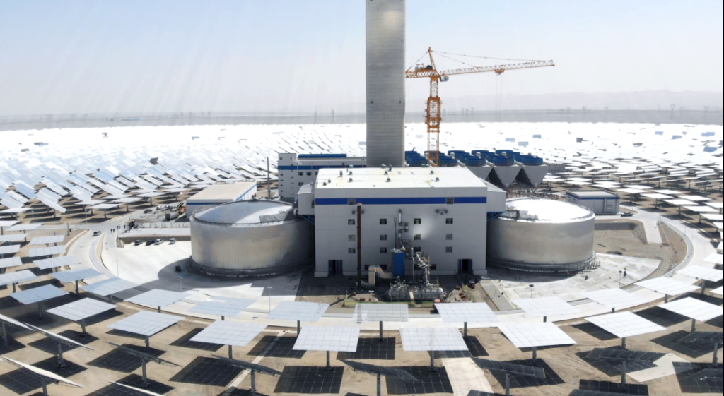
The commonly used valves include molten salt gate valve, molten salt globe valve, molten salt check valve, molten salt butterfly valve, and molten salt control valve. Valves used in molten salt applications must meet the following requirements:
High Temperature Resistance: Designed to withstand temperatures up to 595°C. Molten salt begins to solidify below 260°C, making the valve stem inoperable.
High Thermal Conductivity: Ensuring that molten salt remains above its freezing point.
Excellent Corrosion Resistance: To withstand the strong oxidizing environment of molten salt.
Let’s look at each type of molten salt valve and how they work.
1. Molten Salt Gate Valve
MSG Series molten salt gate valves are suitable for molten salt medium pipelines in solar thermal power generation systems, with nominal pressures of 150LB~1500LB (PN16~PN250), working temperatures of 29℃~700℃, and these valves are used to cut off or connect media during pipeline. This series of products is developed by our THINKTANK combining advanced technologies with our own high-temperature valve manufacturing experience.
MSG Series Features
1. Scientific Material Selection
For temperatures up to 400°C, valve bodies can be made from WCB or A105 material (corresponding to SA106B pipe material).
For temperatures above 400°C, valve bodies are made from CF8C or F347 materials (corresponding to SA376 TP347H pipe material).
2. Valve Seat and Disc
The valve seats use Stellite hard alloy or other surface-hardened materials. Different hardness levels are used, with harder materials used for the valve seats.
3. Surface Hardening
The surfaces of the valve stem and internal components are surface hardened to improve durability and resistance to operational wear.
4. High-Temperature Packing:
The packing materials used are high-temperature and oxidation-resistant metals, which are compatible with molten salt.
5. Design Features
Our molten salt gate valves have a bottom cavity and disc cutting structure, which can prevent fluid accumulation, facilitate easy operation, and ensure tight sealing.
Material List for Molten Salt Gate Valve
| Model | Body/Bonnet Material | Valve Seat | Stem Material | Packing | Operating Temp (°C) |
| MSG/C | A216 Gr. WCB/A105 | Hard Alloy Steel | Stainless steel Nitriding steel | High temperature resistant and anti-oxidation materials | ≤400 |
| MSG/S | CF8C/F347 | Hard Alloy Steel | F347 | High temperature resistant and anti-oxidation materials | 400 < Temp ≤ 700 |
Performance Specification
| Model | Nominal Pressure (MPa) | Shell Test Pressure(MPa) | Seat Test Pressure (MPa) |
| MSG/C/16 | 1.6 | 2.4 | 1.76 |
| MSG/C/25 | 2.5 | 3.8 | 2.75 |
| MSG/C/40 | 4.0 | 6.0 | 4.40 |
| MSG/C/64 | 6.4 | 9.6 | 7.00 |
| MSG/C/100 | 10.0 | 15.0 | 11.00 |
| MSG/C/160 | 16.0 | 24.0 | 17.60 |
| MSG/C/250 | 25.0 | 37.5 | 27.50 |
| MSG/C/150 | 150LB | 3.1 | 2.20 |
| MSG/C/300 | 300LB | 7.8 | 5.60 |
| MSG/C/600 | 600LB | 15.3 | 11.20 |
| MSG/C/900 | 900LB | 23.1 | 16.90 |
| MSG/C/1500 | 1500LB | 37.5 | 27.50 |
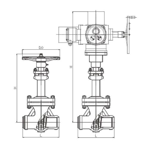
Molten Salt Gate Valve Dimensions PN16-PN100
| Nominal Diameter (DN) | PN16-25 | PN40 | PN64 | PN100 | ||||||||||||
| Size(mm) | L (mm) | H Manual (mm) | Do (mm) | H Electric/Motorized (mm) | L (mm) | H Manual (mm) | Do (mm) | H Electric/Motorized (mm) | L (mm) | H Manual (mm) | Do (mm) | H Electric/Motorized (mm) | L (mm) | H Manual (mm) | Do (mm) | H Electric/Motorized (mm) |
| DN10 | 79 | 258 | 100 | 608 | 79 | 258 | 100 | 658 | 79 | 258 | 100 | 658 | 79 | 258 | 100 | 658 |
| DN15 | 79 | 258 | 100 | 608 | 79 | 258 | 100 | 658 | 79 | 258 | 100 | 658 | 79 | 258 | 100 | 658 |
| DN20 | 92 | 269 | 100 | 619 | 92 | 269 | 100 | 669 | 92 | 269 | 100 | 669 | 92 | 269 | 100 | 669 |
| DN25 | 111 | 297 | 125 | 619 | 111 | 297 | 125 | 697 | 111 | 297 | 125 | 697 | 111 | 297 | 125 | 697 |
| DN32 | 120 | 336 | 160 | 686 | 120 | 336 | 160 | 736 | 120 | 336 | 160 | 736 | 120 | 336 | 160 | 736 |
| DN40 | 120 | 346 | 160 | 696 | 120 | 346 | 160 | 746 | 120 | 346 | 160 | 746 | 120 | 346 | 160 | 746 |
| DN50 | 140 | 383 | 180 | 733 | 140 | 383 | 180 | 793 | 140 | 383 | 180 | 793 | 140 | 383 | 180 | 793 |
| DN65 | 265 | 493 | 240 | 813 | 280 | 511 | 300 | 831 | 280 | 570 | 300 | 890 | 280 | 570 | 300 | 890 |
| DN80 | 280 | 555 | 280 | 855 | 310 | 535 | 320 | 855 | 310 | 618 | 320 | 938 | 310 | 618 | 300 | 938 |
| DN100 | 300 | 620 | 320 | 940 | 350 | 648 | 350 | 968 | 350 | 695 | 350 | 1015 | 350 | 750 | 350 | 1015 |
| DN125 | 325 | 734 | 320 | 1054 | 400 | 680 | 400 | 1054 | 400 | 772 | 400 | 1062 | 400 | 801 | 400 | 1070 |
| DN150 | 350 | 760 | 350 | 1088 | 450 | 760 | 450 | 1088 | 450 | 813 | 450 | 1133 | 450 | 809 | 450 | 1260 |
| DN175 | 375 | 840 | 400 | 1159 | 500 | 870 | 500 | 1250 | 500 | 826 | 500 | 1276 | 500 | 826 | 500 | 1276 |
| DN200 | 400 | 941 | 450 | 1260 | 550 | 960 | 500 | 1550 | 550 | 1032 | 600 | 1472 | 550 | 1030 | 600 | 1472 |
| DN250 | 450 | 1090 | 450 | 1530 | 650 | 1110 | 550 | 1675 | 650 | 1199 | 700 | 1639 | 650 | 1180 | 600 | 1652 |
| DN300 | 500 | 1211 | 550 | 1650 | 750 | 1235 | 600 | 1816 | 750 | 1302 | – | 1752 | 750 | 1265 | 800 | 1762 |
| DN350 | 550 | 1365 | 600 | 1805 | 850 | 1376 | 700 | 2242 | 850 | 1462 | – | 1912 | 850 | 1462 | 800 | 1912 |
| DN400 | 600 | 1477 | 650 | 1927 | 950 | – | – | 2615 | 950 | – | – | 2988 | 950 | 1620 | – | 2082 |
| DN450 | 650 | 1665 | 700 | 2115 | 1050 | – | – | 2645 | 1050 | – | – | 3303 | 1050 | – | – | 2184 |
| DN500 | 700 | 1822 | 800 | 2272 | 1150 | – | – | 2675 | 1150 | – | – | 3470 | 1150 | – | – | 2488 |
| DN600 | 800 | 2096 | – | 2546 | 1350 | – | – | – | 1350 | – | – | 3834 | 1350 | – | – | 2915 |
| DN700 | 900 | – | – | 3196 | 1450 | – | – | – | 1450 | – | – | 3320 | – | – | – | – |
| DN800 | 1000 | – | – | 3400 | 1650 | – | – | – | 1650 | – | – | 3694 | – | – | – | – |
| DN900 | 1100 | – | – | – | – | – | – | – | – | – | – | – | – | – | – | – |
| DN1000 | 1200 | – | – | – | – | – | – | – | – | – | – | – | – | – | – | – |
Molten Salt Gate Valve Dimensions PN160-PN250
| Nominal Diameter (DN) | PN160 | PN250 | ||||||
| Size(mm) | L (mm) | H Manual (mm) | Do (mm) | H Electric/Motorized (mm) | L (mm) | H Manual (mm) | Do (mm) | H Electric/Motorized (mm) |
| DN10 | 92 | 269 | 100 | 619 | 92 | 269 | 100 | 619 |
| DN15 | 111 | 297 | 125 | 647 | 111 | 297 | 125 | 647 |
| DN20 | 111 | 297 | 125 | 647 | 111 | 297 | 125 | 647 |
| DN25 | 120 | 336 | 160 | 686 | 120 | 336 | 160 | 686 |
| DN32 | 120 | 346 | 160 | 686 | 120 | 346 | 160 | 686 |
| DN40 | 140 | 383 | 180 | 733 | 140 | 383 | 180 | 733 |
| DN50 | 178 | 430 | 200 | 780 | 178 | 430 | 200 | 780 |
| DN65 | 340 | 575 | 300 | 895 | 419 | 700 | 300 | 750 |
| DN80 | 390 | 612 | 350 | 940 | 470 | 760 | 300 | 810 |
| DN100 | 450 | 723 | 400 | 1040 | 546 | 852 | 400 | 900 |
| DN125 | 525 | 792 | 400 | 1232 | 673 | 1000 | 400 | 1120 |
| DN150 | 600 | 940 | 550 | 1380 | 705 | 1130 | 400 | 1240 |
| DN200 | 750 | 1140 | 700 | 1590 | 832 | 1280 | 650 | 1320 |
| DN250 | 850 | 1267 | 800 | 1867 | 991 | 1450 | 700 | 1510 |
| DN300 | 965 | 1315 | 800 | 1915 | 1130 | 1680 | 900 | 1740 |
| DN350 | 1029 | 2050 | 900 | 2100 | 1257 | 2080 | 900 | 2130 |
| DN400 | 1130 | – | – | 2250 | 1384 | – | – | 2280 |
| DN450 | 1219 | – | – | 2365 | 1537 | – | – | 2395 |
| DN500 | 1321 | – | – | 2715 | 1664 | – | – | 2745 |
| DN600 | 1549 | – | – | 2790 | 1943 | – | – | 2820 |
Molten Salt Gate Valve Dimensions 150-600LB
| Nominal Diameter (DN) | 150LB | 300LB | 600LB | |||||||||
| Size(mm) | L (mm) | H Manual (mm) | Do (mm) | H Electric/Motorized (mm) | L (mm) | H Manual (mm) | Do (mm) | H Electric/Motorized (mm) | L (mm) | H Manual (mm) | Do (mm) | H Electric/Motorized (mm) |
| DN10 | 79 | 258 | 100 | 658 | 79 | 258 | 100 | 658 | 79 | 258 | 100 | 658 |
| DN15 | 79 | 258 | 100 | 658 | 79 | 258 | 100 | 658 | 79 | 258 | 100 | 658 |
| DN20 | 92 | 269 | 100 | 669 | 92 | 269 | 100 | 669 | 92 | 269 | 100 | 669 |
| DN25 | 111 | 297 | 125 | 697 | 111 | 297 | 125 | 697 | 111 | 297 | 125 | 697 |
| DN32 | 120 | 336 | 160 | 736 | 120 | 336 | 160 | 736 | 120 | 336 | 160 | 736 |
| DN40 | 120 | 346 | 160 | 746 | 120 | 346 | 160 | 746 | 120 | 346 | 160 | 746 |
| DN50 | 140 | 383 | 180 | 733 | 140 | 383 | 180 | 733 | 140 | 383 | 180 | 733 |
| DN65 | 265 | 465 | 240 | 813 | 241 | 480 | 250 | 830 | 330 | 519 | 280 | 869 |
| DN80 | 280 | 555 | 280 | 875 | 283 | 528 | 250 | 878 | 356 | 564 | 280 | 1014 |
| DN100 | 300 | 620 | 300 | 940 | 305 | 600 | 280 | 950 | 432 | 624 | 350 | 1074 |
| DN125 | 325 | 734 | 320 | 1054 | 381 | 703 | 350 | 1053 | 508 | 701 | 400 | 1151 |
| DN150 | 350 | 768 | 350 | 1088 | 403 | 732 | 350 | 1082 | 559 | 771 | 450 | 1221 |
| DN200 | 400 | 941 | 400 | 1260 | 419 | 915 | 400 | 1265 | 660 | 978 | 550 | 1428 |
| DN250 | 450 | 1090 | 450 | 1530 | 457 | 1050 | 450 | 1400 | 787 | 1097 | 600 | 1547 |
| DN300 | 500 | 1211 | 450 | 1650 | 502 | 1194 | 500 | 1544 | 838 | 1235 | 700 | 1685 |
| DN350 | 550 | 1365 | 550 | 1805 | 762 | 1310 | 600 | 1660 | 889 | 1320 | 750 | 1770 |
| DN400 | 600 | 1477 | 600 | 1927 | 838 | 1460 | 700 | 1810 | 991 | – | – | 1945 |
| DN450 | 650 | 1665 | 650 | 2115 | 914 | – | – | 2150 | 1092 | – | – | 2080 |
| DN500 | 700 | 1822 | 700 | 2272 | 991 | – | – | 2442 | 1194 | – | – | 2360 |
| DN600 | 800 | 2096 | 800 | 2546 | 1143 | – | – | 2896 | 1397 | – | – | 2732 |
| DN700 | 900 | – | – | 3196 | 1346 | – | – | 3230 | 1549 | – | – | 3512 |
| DN800 | 1000 | – | – | 3400 | 1524 | – | – | 3450 | 1778 | – | – | 3961 |
| DN900 | 1100 | – | – | 3659 | 1727 | – | – | 3910 | 2082 | – | – | 4410 |
| DN1000 | 1200 | – | – | 4023 | – | – | – | 4130 | 2286 | – | – | 4820 |
Molten Salt Gate Valve Dimensions 900-1500LB
| Nominal Diameter (DN) | 900LB | 1500LB | ||||||
| Size(mm) | L (mm) | H Manual (mm) | Do (mm) | H Electric/Motorized (mm) | L (mm) | H Manual (mm) | Do (mm) | H Electric/Motorized (mm) |
| DN10 | 92 | 269 | 100 | 619 | 92 | 269 | 100 | 619 |
| DN15 | 111 | 297 | 125 | 647 | 111 | 297 | 125 | 647 |
| DN20 | 111 | 297 | 125 | 647 | 111 | 297 | 125 | 647 |
| DN25 | 120 | 336 | 160 | 686 | 120 | 336 | 160 | 686 |
| DN32 | 120 | 346 | 160 | 686 | 120 | 346 | 160 | 686 |
| DN40 | 140 | 383 | 180 | 733 | 140 | 383 | 180 | 733 |
| DN50 | 178 | 430 | 200 | 780 | 178 | 430 | 200 | 780 |
| DN65 | 419 | 670 | 280 | 720 | 419 | 700 | 280 | 750 |
| DN80 | 381 | 730 | 300 | 780 | 470 | 760 | 300 | 810 |
| DN100 | 457 | 822 | 350 | 870 | 546 | 852 | 350 | 900 |
| DN125 | 559 | 970 | 400 | 1090 | 673 | 1000 | 400 | 1120 |
| DN150 | 610 | 1100 | 500 | 1210 | 705 | 1130 | 500 | 1240 |
| DN200 | 737 | 1250 | 650 | 1290 | 832 | 1280 | 650 | 1320 |
| DN250 | 838 | 1420 | 700 | 1480 | 991 | 1450 | 700 | 1510 |
| DN300 | 965 | 1650 | 900 | 1710 | 1130 | 1680 | 900 | 1740 |
| DN350 | 1029 | 2050 | 900 | 2100 | 1257 | 2080 | 900 | 2130 |
| DN400 | 1130 | – | – | 2250 | 1384 | – | – | 2280 |
| DN450 | 1219 | – | – | 2365 | 1537 | – | – | 2395 |
| DN500 | 1321 | – | – | 2715 | 1664 | – | – | 2745 |
| DN600 | 1549 | – | – | 2790 | 1943 | – | – | 2820 |
2. Straight-Through Molten Salt Globe Valve
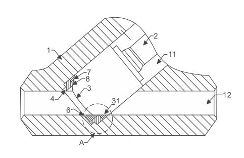
The MSGT series straight-strough molten salt globe valves are designed for nominal pressures ranging from 150LB to 1500LB(PN16 to PN250) and operating temperatures from 29°C to 700°C. These valves are used to cut off the medium in molten salt pipelines in solar thermal power generation systems. THINKTANK’s straight-through globe valves have the following structural features.
No Liquid Accumulation and Low Flow Resistance
Design: The installation design ensures no liquid accumulation and minimal flow resistance, equivalent to the resistance of the pipeline itself.
Scientific Material Selection
Temperature ≤ 400°C: The valve body can be made from WCB or A105 materials, which correspond to pipeline material SA106B.
Temperature > 400°C: The valve body can be made from CF8C or F347 materials, which correspond to pipeline material SA376 TP347H.
Durable Valve Seat
Materials: The valve seats use Stellite hard alloy or other surface-hardening materials.
Hardness: Different hardness levels are used for the valve seat and disc, with the harder material used for the valve seat to enhance durability.
Hardened Surface
Valve Stem and Internals: The surfaces of the valve stem and internal parts undergo surface hardening treatment to improve wear resistance and longevity.
High-Temperature Packing
Materials: The valve packing uses high-temperature, oxidation-resistant metal materials compatible with molten salt, ensuring a reliable seal.
Key Technical Features
Full Bore Straight-Through Design:
Flow Efficiency: The full bore straight-through design paired with a valve core annular groove scraper and tapered sealing structure ensures minimal flow resistance and prevents liquid accumulation at any installation position.
Optimal Material Choices:
For ≤ 400°C Applications: A216WCB (Cast Steel) and A105 (Forged Steel) are suitable for temperatures up to 400°C, matching with SA106B pipeline material.
For > 400°C Applications: CF8C (a high-temperature stainless steel) and F347 (austenitic chromium steel) are chosen for temperatures exceeding 400°C, matching with SA376 TP347H pipeline material.
Enhanced Durability:
Valve Seats and Discs: Utilizing Stellite or other hard alloys, with a preference for using harder materials for valve seats, ensures longevity and reduced wear.
Surface Hardening: This treatment on the valve stem and internal components enhances their durability and resistance to high-temperature corrosion.
Effective Sealing:
High-Temperature Packing: Metal packing materials that resist high temperatures and oxidation, compatible with molten salt, are used to maintain an effective seal under extreme conditions.
3. Molten Salt Y Type Globe Valve
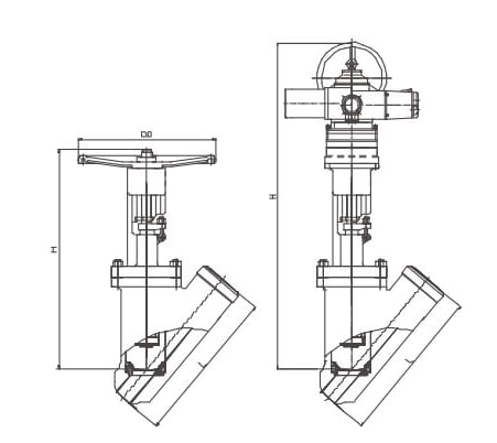
MSYG Series Molten salt Y-type stop valve can be installed in parallel with pipelines. Compared with the straight though molten salt globe valve, it has a larger flow resistance and may have a small amount of liquid accumulation. At present, this valve is widely used in molten salt working conditions.
4. Molten Salt Check Valve
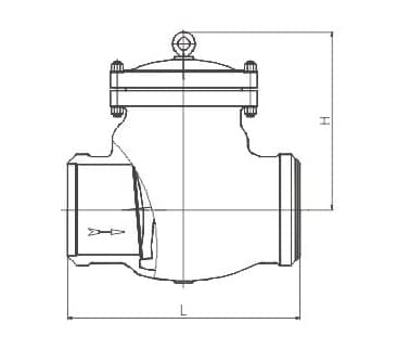
The MSC series molten salt check valve is designed for use in molten salt medium pipelines within concentrated solar power systems. It is suitable for nominal pressures ranging from 150Lb to 1500Lb (PN16 to PN250) and operating temperatures between 29°C and 700°C. The valve is used as a safety device to prevent the medium from flowing backward.
5. Molten Salt Butterfly Valve
Molten salt butterfly valves provide reliable performance, tight sealing, and minimal maintenance for Concentrated Solar Power (CSP) plant operators using molten salt. These valves are critical in industrial processes or thermal energy storage for power generation, capable of withstanding temperatures from 260°C (500°F) to 600°C (1,112°F).
Key Features and Benefits
Temperature Resistance: These valves can operate efficiently within the extreme temperature range required for CSP applications, ensuring the molten salt remains in a liquid state and preventing solidification.
Sealing and Leak Prevention: The standard live-loaded Thermiculite and composite packing design and structure effectively eliminate the possibility of leaks, even under high-temperature and high-pressure conditions. The triple offset design ensures that the disc contacts the seat only at the final point of closure, minimizing wear and extending the valve’s lifespan.
Durability and Maintenance: The robust construction of triple offset butterfly valves ensures long-term durability and minimal maintenance requirements. This is essential for reducing operational costs and downtime in CSP plants.
Corrosion Resistance: The materials used in the construction of these valves offer excellent resistance to the corrosive nature of molten salt, ensuring reliable performance over the valve’s service life.
Tight Sealing: The triple offset design provides a metal-to-metal seal that is both bubble-tight and reliable, essential for maintaining the integrity of the CSP system and preventing molten salt leaks.

Application in CSP Systems:
Heat Absorption Towers: Triple offset butterfly valves are used to control the flow of molten salt through the heat absorption towers, ensuring efficient heat transfer and storage.
Cold and Hot Molten Salt Storage Tanks: These valves manage the flow between the storage tanks and the rest of the CSP system, maintaining the required temperatures and preventing solidification.
Heat Exchangers and Pumps: Ensuring precise flow control and reliable operation, these valves are essential components in the heat exchanger and pump systems of CSP plants.
6. Molten Salt Control Valve
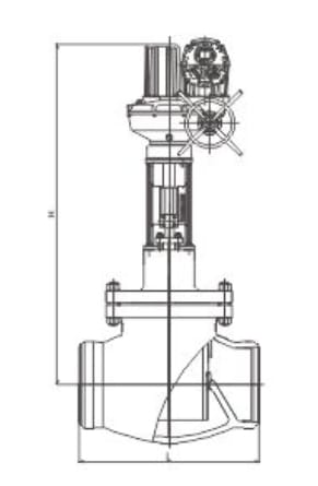
The MSCV series molten salt control valve is used in molten salt medium pipelines within concentrated solar power systems. It is suitable for nominal pressures ranging from 150LB to 1500LB (PN16 to PN250) and operating temperatures between 29°C and 700°C. This valve is used to regulate the flow rate of the controlled medium, ensuring that the process parameters remain at the specified values.
| Nominal Diameter (DN) | 150LB | 300LB | 600LB | 900LB | 1500LB | |||||
| Size(mm) | L | H | L | H | L | H | L | H | L | H |
| DN10 | 170 | 739 | 170 | 739 | 170 | 739 | 170 | 739 | 170 | 739 |
| DN15 | 170 | 739 | 170 | 739 | 170 | 739 | 170 | 739 | 170 | 739 |
| DN20 | 170 | 739 | 170 | 739 | 170 | 739 | 170 | 739 | 170 | 739 |
| DN25 | 170 | 739 | 170 | 739 | 170 | 739 | 170 | 739 | 170 | 739 |
| DN32 | 200 | 787 | 200 | 787 | 200 | 787 | 200 | 787 | 200 | 787 |
| DN40 | 200 | 787 | 200 | 787 | 200 | 787 | 200 | 787 | 200 | 787 |
| DN50 | 250 | 806 | 250 | 806 | 250 | 806 | 250 | 806 | 250 | 806 |
| DN65 | 216 | 804 | 292 | 859 | 336 | 859 | 360 | 835 | 360 | 865 |
| DN80 | 241 | 822 | 368 | 898 | 406 | 898 | 419 | 945 | 419 | 975 |
| DN100 | 292 | 878 | 356 | 944 | 432 | 944 | 457 | 1125 | 546 | 1155 |
| DN125 | 356 | 900 | 400 | 1004 | 508 | 1004 | 559 | 1210 | 673 | 1240 |
| DN150 | 406 | 921 | 444 | 1115 | 634 | 1115 | 670 | 1318 | 705 | 1398 |
| DN200 | 495 | 1025 | 544 | 1242 | 660 | 1242 | 737 | 1419 | 832 | 1479 |
| DN250 | 622 | 1273 | 622 | 1273 | 622 | 1273 | 622 | 1537 | 991 | 1567 |
| DN300 | 698 | 1391 | 711 | 1572 | 838 | 1572 | 965 | 1556 | 1130 | 1586 |
| DN350 | – | – | – | – | – | – | 1029 | 1690 | 1257 | 1720 |
| DN400 | – | – | – | – | – | – | 1092 | 1824 | 1406 | 1854 |
Features
1. Guided Piston Disc
The disc is guided at both the top and bottom, forming a piston-type disc that is fully guided within the valve body cavity. This design eliminates problems such as sticking, surface scratches, and disc vibration caused by various forces.
2. Upper Chamber Communication
The upper chamber is always connected to the inlet, preventing liquid accumulation in the middle chamber, which could lead to insufficient valve stroke. The lower chamber adjusts the flow, providing strong flow capacity.
3. Material Selection
For design temperatures ≤400°C, the valve body can be made of WCB or A105 materials (corresponding to SA106B pipe material). For design temperatures >400°C, the valve body can be made of CF8C or F347 materials (corresponding to SA376 TP347H pipe material).
4. Hard Alloy Seat
The valve seat is made of Stellite hard alloy or other surface-hardened materials, with different hardness for the seat and disc, using the harder material for the seat.
5. Surface Hardening
The valve stem and internal parts are surface hardened.
6. High-Temperature Packing
The valve packing is made of high-temperature oxidation-resistant metal materials that are compatible with molten salt.
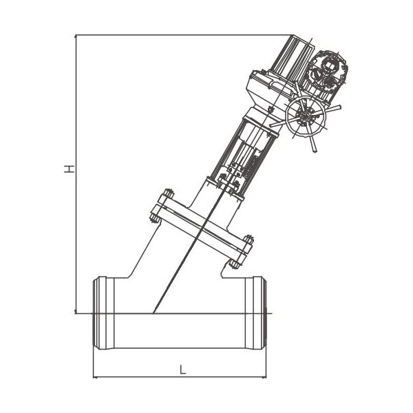
Molten Salt Control Valve Dimensions 150-1500LB
| Nominal Diameter (DN) | 150LB | 300LB | 600LB | 900LB | 1500LB | |||||
| Size(mm) | L | H | L | H | L | H | L | H | L | H |
| DN10 | 140 | 743 | 140 | 743 | 140 | 743 | 140 | 743 | 140 | 743 |
| DN15 | 140 | 743 | 140 | 743 | 140 | 743 | 140 | 743 | 140 | 743 |
| DN20 | 140 | 743 | 140 | 743 | 140 | 743 | 140 | 743 | 140 | 743 |
| DN25 | 140 | 743 | 140 | 743 | 140 | 743 | 140 | 743 | 140 | 743 |
| DN32 | 180 | 797 | 180 | 797 | 180 | 797 | 180 | 797 | 180 | 797 |
| DN40 | 180 | 797 | 180 | 797 | 180 | 797 | 180 | 797 | 180 | 797 |
| DN50 | 250 | 807 | 250 | 807 | 250 | 807 | 250 | 807 | 250 | 807 |
| DN65 | 266 | 804 | 342 | 859 | 360 | 859 | 360 | 835 | 360 | 865 |
| DN80 | 291 | 822 | 368 | 898 | 406 | 898 | 419 | 945 | 419 | 975 |
| DN100 | 342 | 878 | 406 | 944 | 482 | 944 | 457 | 1125 | 546 | 1155 |
| DN125 | 431 | 900 | 475 | 1004 | 583 | 1004 | 559 | 1210 | 673 | 1240 |
| DN150 | 481 | 921 | 519 | 1115 | 634 | 1115 | 610 | 1318 | 705 | 1398 |
| DN200 | 570 | 1025 | 634 | 1242 | 725 | 1242 | 737 | 1419 | 832 | 1479 |
| DN250 | 722 | 1273 | 722 | 1273 | 722 | 1273 | 838 | 1537 | 991 | 1567 |
| DN300 | 798 | 1391 | 811 | 1572 | 938 | 1572 | 965 | 1586 | 1130 | 1586 |
| DN350 | – | – | – | – | – | – | 1029 | 1690 | 1257 | 1720 |
| DN400 | – | – | – | – | – | – | 1092 | 1824 | 1406 | 1854 |
Performance of Molten Salt Valves
High-temperature molten salt valves are critical components that significantly impact the stability and reliability of the entire concentrated solar power (CSP) system. Below are the main performance indicators of high-temperature molten salt valves.
Pressure Resistance: These valves have to withstand high working pressures, typically around 10-20 MPa.
Heat Resistance: The valves have to work well in high-temperature environments, usually between 600-700°C.
Flow Control: These valves must have precise flow control to ensure the stability and reliability of the system.
Sealing Performance: The valves must seal well to prevent leakage of the medium.
Corrosion Resistance: High-temperature molten salt valves must have good corrosion resistance to withstand the corrosive nature of molten salt.
Applications of High-Temperature Molten Salt Valves in New Energy Solar Thermal Power Generation
High-temperature molten salt valves have a wide range of applications in new energy solar thermal power generation. Here are a few applications.
Solar Thermal Power Generation: In solar thermal power systems, high-temperature molten salt valves are typically used in solar heat collection systems to control the flow and temperature of the medium.
Nuclear Power Generation: In nuclear power generation, these valves are commonly used in cooling systems to control the flow and temperature of the cooling medium.
Biomass Power Generation: In biomass power generation, high-temperature molten salt valves are often used in combustion chambers and waste heat recovery systems to control the flow and temperature of the medium.
Operating Temperature
You can achieve different working temperatures by using different salt mixtures.
Cold Salt: Kept at 752°F (400°C), stored in salt storage tanks, and heated to keep the salt above its solidification temperature.
Hot Salt: Kept at 1112°F (600°C), stored in an outlet tank, and ready for power generation.
You can form molten salt from two types of mixtures: binary and ternary eutectic mixtures of different salts.
Binary Mixture of Sodium Nitrate/Potassium Nitrate: This mixture is typically used within a temperature range of 509° to 1049°F (265° to 565°C) to make sure you have a sufficient safety margin above the freezing point. However, this salt starts to degrade above 1049°F (565°C) and will slowly decompose into nitrogen and nitrogen oxides beyond this temperature.
Ternary Mixture of Lithium Nitrate/Sodium Nitrate/Potassium Nitrate: This alternative has a eutectic melting point of 130°C (266°F). Compared to the binary mixture, its drawback is that you can only use it up to a maximum temperature of about 932°F (500°C). Above 500°C (932°F), lithium nitrate starts to break down. Also, this mix is more expensive than the sodium or potassium salts.
Recommendations for Using Molten Salt:
The fluid temperature should be at least 20° to 30°C (36° to 54°F) above the melting point to minimize the risk of freezing due to potential cold spots.
Keep the maximum operating temperature of the salt at least 20°C (36°F) below the degradation temperature.
Design Specifications for Molten Salt Valves
Using molten salt is challenging due to its melting and freezing points. However, with proper system design, molten salt can give you excellent heat transfer performance and minimal degradation over the life of the system.
Here are the basic process and technical challenges for designing molten salt valves.
High Operating Temperature: The pipelines for molten salt operate at high temperatures, typically close to 600°C (1115°F).
Corrosive Fluid: Depending on the type of salt used (chlorides, fluorides, sodium nitrate NaNO3, potassium nitrate KNO3), the fluid can be highly corrosive.
High Flow Rates: The valves must handle high flow rates well.
High Reliability and Longevity: The system requires valves that are highly reliable and have a long operational life without frequent shutdowns.
Perfect Sealing: The valves must provide excellent sealing both in-line and to the atmosphere to prevent any leakage.
To address these challenges, you need to consider the following when designing molten salt valves:
Material Selection: Use materials that can withstand high temperatures and resist corrosion. Common materials include high-grade stainless steel or specialized alloys.
Valve Design: Make sure the valve design can handle high flow rates and can operate efficiently at high temperatures.
Sealing Mechanisms: Use advanced sealing technologies that can maintain integrity at extreme temperatures and prevent leaks.
Maintenance and Inspection: Design the system for easy maintenance and regular inspection to ensure long-term reliability and performance.
Thermal Management: Implement thermal insulation and heating systems to keep the molten salt above its freezing point so it doesn’t solidify in the valves and pipelines.
Why Choose THINKTANK’s Molten Salt Valves
As one of the professional manufacturers of molten salt valves, THINKTANK understands the challenges these valves face under servere conditions. The valve performance must not only adapt to high temperature and high corrosion media but also require dual protection from electric heating tracing (EHT) and insulation materials. This ensures that the valve maintains sufficient temperature during operation to keep the molten salt in a liquid state.

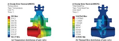
First, we need to create a temperature distribution map for the various parts of the valve to determine the heat tracing requirements. These needs vary depending on the specific application. For example, for valves used in cold salt applications, the normal operating temperature is 400°C. So we typically install EHT in the valve body and top neck these two main areas.
We need to heat the middle of the valve body to keep the temperature above the melting point of the molten salt. We also need to monitor the temperatures of the valve neck and bottom closure. If necessary, we provide auxiliary heating to prevent the salt from freezing in these areas. It is essential to install thermal sensors in critical areas to monitor the temperature.
Especially for the valve neck, which usually extends to the stuffing box, if the temperature drops in this area, the salt inside the stuffing box can freeze. This makes it difficult to operate the valve and sometimes causes the valve to seize.
Thermal Finite Element Analysis (FEA) is a critical step in our design process. It helps us understand thermal stresses at high temperatures and the temperature distribution in the packing and bottom guide areas. These analysis results allow us to strategically place the packing to ensure its temperature remains above the salt’s freezing point. Transient thermal analysis lets us simulate thermal shock, studying the stress generated in the valve body and bolt areas during rapid cooling.
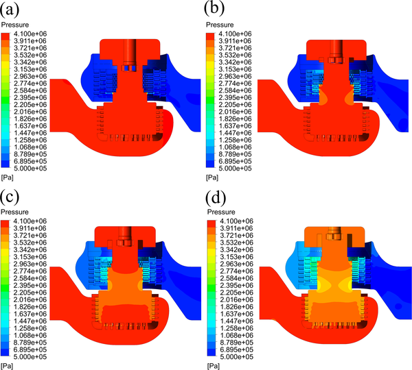
We also learn from Flowserve, a leading brand in the molten salt valve industry, by testing each valve design in molten salt test loops. We test and select the appropriate packing and gaskets to ensure that the valve performance in actual use is not compromised.
Here are some related professional molten salt valve procedures.
1. Verify the thermal loss of the valve design and draw the temperature distribution map of the entire valve.
2. Use appropriate software for thermal simulation and compare the results with actual test data to extend the design to other valve sizes.
3. Determine the sizing design procedures of the heat tracing system.
4. Test sealing elements to ensure correct selection.
5. Assess the wear and corrosion resistance of components.
6. Review the feasibility of online replacement of packing and gaskets for easy maintenance.
Based on above experience of valves design and manufacturing molten salt applications, we can show our molten salt valve has the following advantages.
Auxiliary Heating Design: The valve structure is designed to accommodate auxiliary heating installations, which allows the application of electric trace heating and insulation measures on-site for pipeline equipment.
Superior Corrosion Resistance: Valves are made from austenitic steel or even Inconel alloy, which offer superior corrosion resistance.
Triple Sealing Stem: The valve stem features a back-seal function with special sealing rings, an enhanced high-pressure and corrosion-resistant bellows seal, and triple sealing to ensure reliability under extreme conditions.
Self-Cleaning Valve Plug and Seat: The valve plug and seat are designed to be self-cleaning, ensuring no residue remains in the flow path.
Fully Enclosed Stem and Packing Gland Bolts: The stem and packing gland bolts are fully enclosed to prevent contamination from atmospheric dust and sand, ensuring smooth operation.
Metal Sealing Rings: The use of metal sealing rings made from the same material as the valve body replaces conventional gaskets, eliminating leakage at the valve body and bonnet joint.
High-Temperature Molten Salt Sealing Gaskets: These gaskets can withstand temperatures up to 1000°C, are oxidation-resistant, and can endure corrosion from high-temperature molten salt and other strong oxidizers.
Summary
In summary, molten salt valves are critical components in high-temperature applications, especially in clean energy technologies like CSP plants. We design, manufacturing, test and maintain them to make sure they work reliably and efficiently. Should you have any question of molten salt valves, please do not hesitate to contact us.
