
Step-by-step procedures, expert troubleshooting and setup guides for all major valve positioner brands and models.
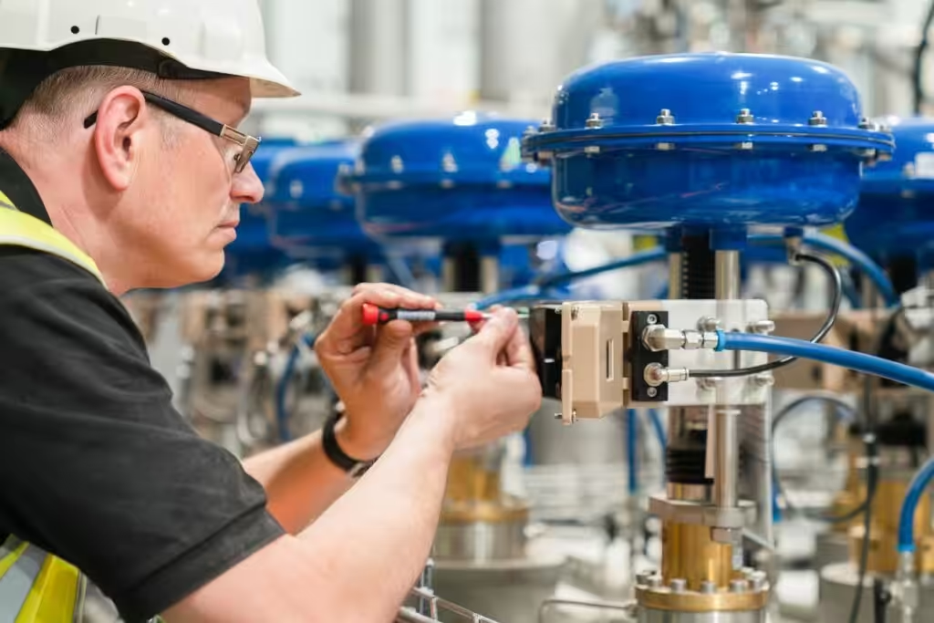
Select the symptom that most closely matches the field condition.
The positioner receives a signal, but the actuator or valve remains stationary.
The valve stops before reaching the fully open or fully closed position.
The positioner cannot detect the actuator travel or complete its setup cycle.
The valve continuously oscillates around the target position.
The displayed position does not match the actual valve travel.
The valve moves correctly but responds more slowly than required.
The valve moves correctly but responds more slowly than required.
The valve fails to move to the specified FC, FO or fail-in-place condition.
This guide applies to pneumatic, electro-pneumatic and digital valve positioners installed on linear or rotary control valves. It covers both single-acting and double-acting pneumatic actuators and provides a general commissioning framework that can be applied across different positioner manufacturers.
Positioners that use a pneumatic control signal, commonly 3–15 psi or 0.2–1.0 bar.
Positioners that convert a 4–20 mA electrical input signal into a pneumatic output.
Microprocessor-based positioners with automatic initialization, diagnostics, communication and configurable control parameters.
Used on globe valves, angle valves and other linear-stroke control valves.
Used on ball valves, butterfly valves, eccentric rotary valves and other quarter-turn valves.
Before starting commissioning, verify the following valve, actuator, positioner and operating data. Correct input data helps prevent travel mismatch, incorrect fail action and repeated calibration failures.
| Required Information | Example | Required Information | Example |
|---|---|---|---|
| Valve Tag Number | FV-101 | Positioner Manufacturer | Fisher |
| Valve Type | Globe Control Valve | Positioner Model | DVC6200 |
| Valve Size and Rating | DN80 PN40 | Input Signal | 4–20 mA |
| Flow Direction | Flow-to-Open | Supply Pressure | 2.5 bar |
| Actuator Type | Pneumatic Diaphragm | Output Configuration | Single-Acting |
| Actuator Action | Air-to-Open | Feedback Type | Lever / Linkage |
| Required Fail Position | Fail Close | Hazardous Area Classification | Zone 1 |
| Rated Valve Travel | 25 mm | Process Differential Pressure | 12 bar |
| Actuator Bench Range | 0.4–1.2 bar | Required Stroking Time | 5 seconds |
* Important: The positioner cannot be commissioned correctly without confirming the actuator action, valve travel and required fail position. Do not rely only on the positioner display or previous settings.
Before applying air pressure or starting calibration, verify that the positioner configuration matches the valve, actuator and project control requirements.
| Actuator arrangement | Increasing air pressure | Loss of air | Typical fail position |
|---|---|---|---|
| Air-to-open, spring-to-close | Opens the valve | Closes the valve | Fail close |
| Air-to-close, spring-to-open | Closes the valve | Opens the valve | Fail open |
| Double-acting actuator | Depends on output-port configuration | Depends on pneumatic accessories | Fail close, fail open or fail in place |
Important: “Air-to-open” and “fail-close” describe different conditions. Air action describes how the actuator responds to increasing pressure, while fail position describes the required valve position after loss of air, signal or power.
Confirm the data against:
The valve action, actuator action, required fail position, rated travel, positioner signal and output configuration are confirmed and consistent with the project requirements.
Do not continue if the fail-action requirement or actuator configuration cannot be confirmed.
Inspect the complete mechanical connection between the positioner, actuator and valve before applying automatic calibration.
Poor mounting geometry may allow calibration to finish while still producing inaccurate travel indication, non-linearity or unstable control.
Verify that:
Verify that:
Where site procedures permit, move the valve slowly through part of its travel and check for:
The positioner is securely mounted, the feedback mechanism moves smoothly through the full required range, and the physical valve position corresponds to the positioner feedback direction.
The positioner requires clean, dry and stable instrument air with sufficient pressure and flow capacity.
A pressure gauge showing an acceptable static pressure does not necessarily confirm that sufficient air flow is available while the actuator is moving.
Check:
The available air pressure must be sufficient to overcome:
Engineering note: A valve may complete a no-load stroke test but fail to reach full travel under operating pressure if actuator thrust or supply pressure is insufficient.
Confirm that:
For a single-acting actuator:
For a double-acting actuator:
Inspect:
Use an approved leak-detection method suitable for the site.
The positioner receives clean and stable instrument air, all tubing is correctly connected, and no significant leakage or flow restriction is present.
Confirm the actual signal at the positioner terminals rather than relying only on the DCS or control-system display.
For a standard 4–20 mA input:
| Input current | Typical command |
|---|---|
| 4 mA | 0% |
| 8 mA | 25% |
| 12 mA | 50% |
| 16 mA | 75% |
| 20 mA | 100% |
This relationship may be reversed when reverse action is required.
Confirm:
Where a separate 4–20 mA feedback signal is used, verify:
The positioner receives the correct and stable electrical signal, wiring polarity is correct, communication is available where required, and position feedback is properly scaled.
Do not immediately start automatic initialization after wiring and air connections are completed.
First apply a small and controlled signal change to verify the actual valve movement direction.
Where the positioner permits manual output control:
The following indications must be consistent:
Do not proceed with automatic calibration if:
A controlled signal increase produces the required actuator and valve movement, and the displayed position changes in the correct direction.
Calibration establishes the relationship between the input signal, pneumatic output and actual valve travel.
Only start calibration after the mechanical, pneumatic and electrical checks have been completed.
Smart positioners may automatically determine:
Confirm that:
Observe:
Stop the procedure if the valve repeatedly strikes a mechanical stop or cannot complete its movement.
Important: Do not repeatedly restart automatic initialization without identifying why the previous attempt failed.
Manual calibration may be required for:
Typical manual adjustments include:
Zero adjustment establishes the valve position corresponding to the minimum input signal.
Span adjustment establishes the amount of valve travel produced between the minimum and maximum input signals.
After changing zero, recheck span. After changing span, recheck zero. Several adjustment cycles may be required on mechanical or analog positioners.
Calibration should only be accepted when:
Successful calibration does not prove that the actuator is correctly sized or that the valve can close against the actual process differential pressure.
After calibration, test the complete valve assembly across its operating range.
Do not verify only the 0% and 100% positions.
0% → 25% → 50% → 75% → 100%
100% → 75% → 50% → 25% → 0%
| Input signal | Command | Actual travel | Feedback | Output pressure | Response time | Result |
|---|---|---|---|---|---|---|
| 4 mA | 0% | |||||
| 8 mA | 25% | |||||
| 12 mA | 50% | |||||
| 16 mA | 75% | |||||
| 20 mA | 100% |
Repeat the test in the decreasing direction to identify hysteresis and deadband.
Do not rely exclusively on the positioner display.
Verify:
A positioner may display 100% even when the valve has not reached its true mechanical endpoint.
Where stroking-time requirements apply, measure:
Do not increase stroking speed without evaluating the effect on:
The valve reaches and maintains each commanded position, travels smoothly in both directions, and meets the required stroke, feedback and response-time criteria.
The final step is to confirm that the valve moves to the specified safe position under each relevant failure condition.
The required test depends on the control and shutdown arrangement.
Simulate loss of the 4–20 mA command or apply the configured low-signal failure condition.
Verify:
Where the positioner, solenoid valve or accessories require electrical power, isolate the power supply according to the approved procedure.
Verify the final valve condition.
Isolate or reduce the air supply in a controlled manner.
Verify:
Where a solenoid valve is part of the shutdown circuit:
For double-acting systems designed to fail in place, verify that:
After the failure test, compare:
Before returning the valve to service:
The valve moves to the specified fail position under each applicable failure condition, all local and remote indications agree, and the valve is safely restored to its required operating state.
Valve-positioning problems do not always originate from the positioner itself. Air supply, electrical signals, mechanical linkage, actuator sizing, packing friction, valve internals and process differential pressure can produce similar symptoms.
Use the following symptom-based checks to identify the most likely fault area before replacing or recalibrating the positioner.
Safety Notice: Valve movement may occur unexpectedly during troubleshooting. Confirm that the valve can be safely stroked and follow the applicable process-isolation, lockout/tagout and hazardous-area procedures.
| Test result | Most likely fault area |
|---|---|
| No input current at the positioner | Wiring, DCS output or loop power |
| Input current is correct, but no positioner output pressure | Positioner, I/P module or pneumatic relay |
| Output pressure changes, but actuator does not move | Actuator leakage, mechanical lock or insufficient force |
| Actuator moves, but valve stem does not move | Stem connector, coupling or mechanical linkage |
| Valve moves without process pressure but not under operating conditions | Insufficient actuator force or excessive process load |
Do not replace the positioner solely because the valve does not move. Confirm whether the positioner is generating pneumatic output first.
| Observation | Likely explanation |
|---|---|
| Positioner reads 100%, but physical travel is incomplete | Feedback or calibration error |
| Valve reaches endpoint without process load only | Insufficient actuator force or excessive process force |
| Valve stops at exactly the same position each time | Mechanical restriction, trim damage or configured travel limit |
| Output pressure reaches supply pressure, but valve still does not move | Actuator force is insufficient or valve is mechanically stuck |
| Valve reaches one endpoint only | Incorrect zero/span, linkage geometry or actuator pressure imbalance |
If the valve reaches full travel during workshop testing but fails under operating pressure, the root cause is unlikely to be calibration alone.
Do not repeatedly restart initialization without identifying the cause of the failed travel detection. Repeated impacts against mechanical stops can damage the valve, actuator or linkage.
| Test result | Most likely source |
|---|---|
| Stable in local/manual mode but unstable in automatic mode | Process loop or PID tuning |
| Unstable in both manual and automatic modes | Positioner tuning, friction or mechanical issue |
| Oscillation begins after booster installation | Booster bypass or pneumatic capacity mismatch |
| Position remains still and then suddenly jumps | Stick-slip or excessive packing friction |
| Instability occurs mainly near the closed position | Oversized valve, seat interaction or cutoff setting |
Positioner hunting and process-loop oscillation are not the same fault. Always determine whether the instability remains when the valve is controlled locally.
Never assume that the displayed percentage represents actual valve travel. Verify the physical position during commissioning.
| Observation | Likely cause |
|---|---|
| Both directions are slow | Supply restriction, low pressure or actuator volume |
| Only one direction is slow | Output restriction, asymmetric friction or accessory fault |
| Output pressure changes immediately, but movement is delayed | Actuator or valve friction |
| Supply pressure collapses during movement | Inadequate regulator, tubing or air capacity |
| Initial movement is delayed and then sudden | Stick-slip friction |
Increasing valve speed without evaluating the process can create overshoot, pressure surge, water hammer or unstable control.
Some pneumatic and electro-pneumatic positioners have a continuous bleed by design. Confirm the manufacturer’s normal steady-state air-consumption specification before declaring a fault.
Continuous exhaust may be a consequence of the positioner trying to correct a valve that cannot reach the commanded position. Check valve travel before replacing the positioner.
Do not change software direction settings simply to make the display appear correct. Confirm the physical valve and actuator action first.
Test each relevant failure separately:
For each test, observe:
Fail close, fail open and fail in place must be verified by physical testing. Positioner configuration alone does not prove the final fail position.
Repeated auto-tuning cannot eliminate a mechanical sticking problem.
Check the following at 0%, 25%, 50%, 75% and 100%:
| Symptom | First check | Most likely fault areas |
|---|---|---|
| Valve does not move | Input signal and output pressure | Signal, air supply, positioner, actuator or valve |
| Cannot reach full travel | Actual travel and output pressure | Calibration, linkage, actuator force or valve restriction |
| Initialization fails | Feedback movement and endpoint access | Linkage, configuration, air supply or friction |
| Valve hunts | Stability in manual mode | Positioner tuning, friction or PID loop |
| Feedback is incorrect | Physical position versus feedback | Linkage, sensor or DCS scaling |
| Response is slow | Pressure during movement | Tubing, regulator, actuator volume or friction |
| Continuous air exhaust | Leakage location and command deviation | Normal bleed, relay, actuator or tubing leakage |
| Wrong travel direction | Physical movement after a small signal change | Configuration, output ports or feedback direction |
| Incorrect fail action | Individual loss-of-signal, power and air tests | Actuator, solenoid, trip circuit or configuration |
| Jerky movement | Output pressure before movement | Packing, stem, trim or linkage friction |
| Position drifts | Output-pressure decay | Pneumatic leakage or insufficient holding force |
| Indications disagree | Compare all indications at known positions | Scaling, wiring, cams or mechanical indication |
The same field symptom may originate from more than one part of the control valve assembly. Use this table as an initial fault-location guide, then complete the detailed diagnostic checks before replacing any component.
| Symptom | Positioner | Actuator | Valve |
|---|---|---|---|
| Valve Does Not Move | ✓ | ✓ | ✓ |
| Valve Cannot Reach Full Travel | ✓ | ✓ | ✓ |
| Auto-Calibration or Initialization Fails | ✓ | ✓ | ✓ |
| Valve Position Is Unstable or Hunting | ✓ | ✓ | ✓ |
| Valve Response Is Too Slow | ✓ | ✓ | ✓ |
| Continuous Air Exhaust or High Air Consumption | ✓ | ✓ | — |
| Position Feedback Is Incorrect | ✓ | ✓ | — |
| Valve Moves in the Wrong Direction | ✓ | ✓ | — |
| Fail Action Is Not Correct | ✓ | ✓ | ✓ |
| Valve Movement Is Jerky, Sticks or Jumps | ✓ | ✓ | ✓ |
| Valve Position Drifts After Reaching the Setpoint | ✓ | ✓ | ✓ |
| Local and Remote Position Indications Do Not Agree | ✓ | ✓ | — |
* Do not replace the positioner before confirming the actual input signal, output pressure, actuator movement and physical valve travel. Many apparent positioner faults are caused by air-supply restrictions, actuator leakage, mechanical linkage or valve friction.
Access practical commissioning, calibration and configuration procedures for commonly used valve positioners. Each guide is organized by the actual field tasks engineers need to complete, including travel calibration, actuator setup, fail-action verification, feedback configuration and diagnostic adjustments.
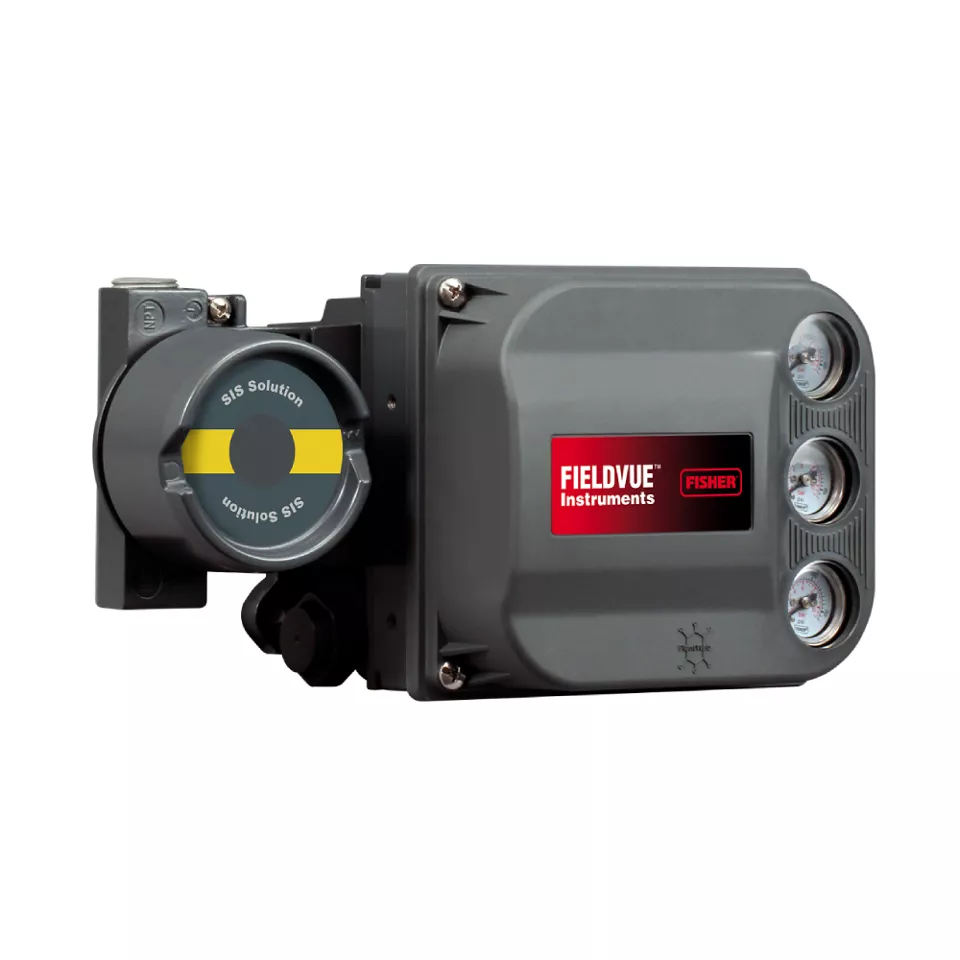
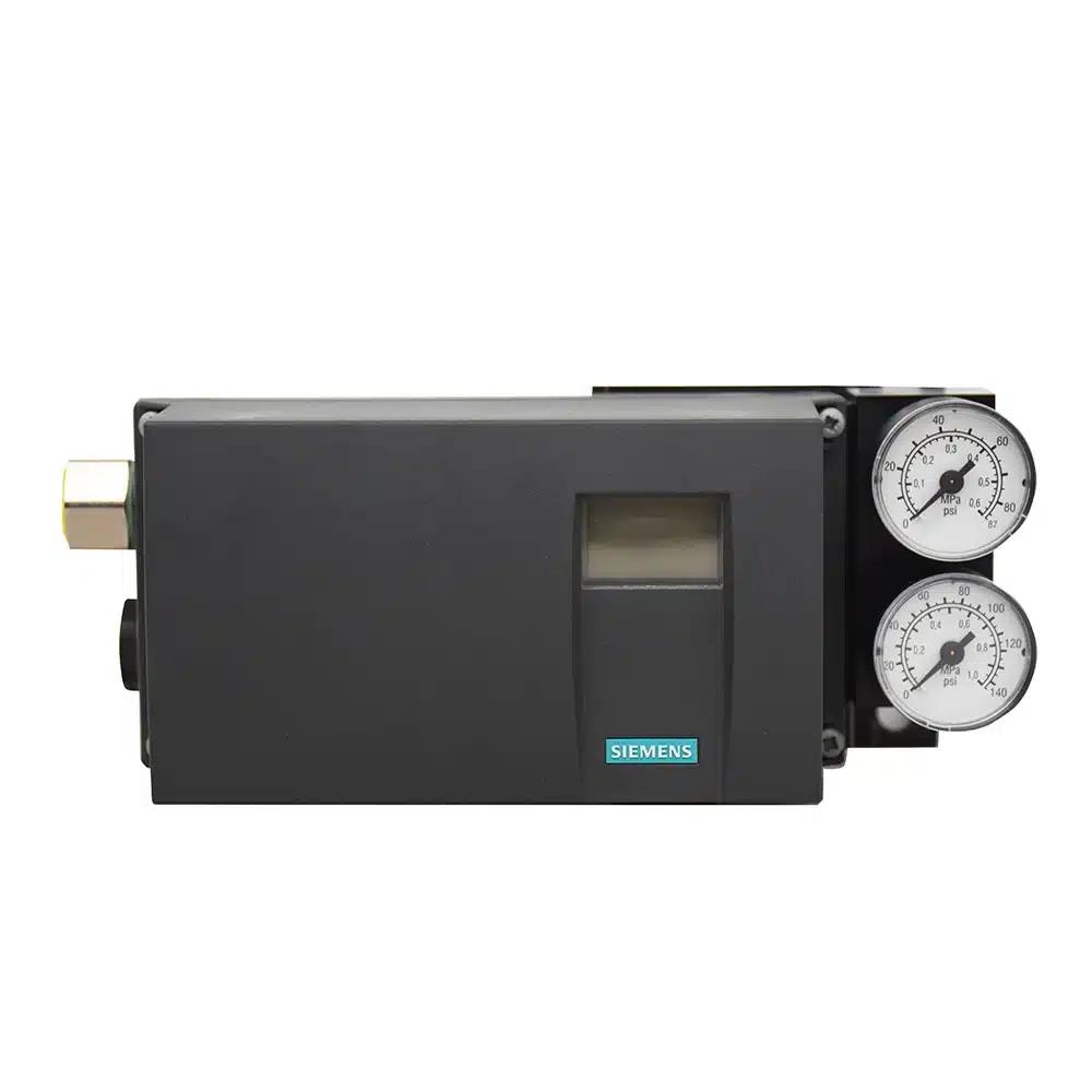

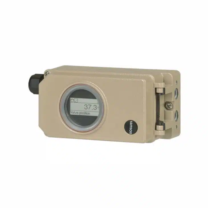
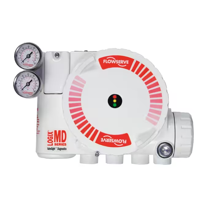
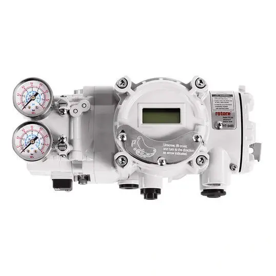
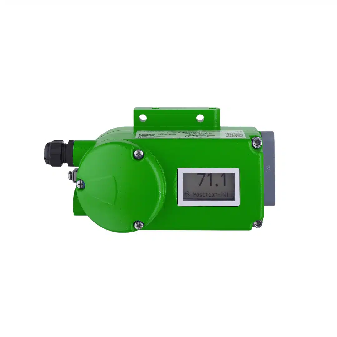
The brand and model names shown on this page are trademarks of their respective owners. These independent field guides are prepared by THINKTANK for general commissioning and troubleshooting reference and are not substitutes for the latest official manufacturer manuals.
WhatsApp us
Avoid your inquiry is delay response, please enter your WhatsApp/Wechat/Skype along with the message, so we can contact you at the very first time.
We will reply you within 24 hours. If for urgent case, please add WhatsApp: +86 185 1656 9221, or WeChat: +86 199 2125 0077. or call +86 189 5813 8289 directly.

We will reply you within 24 hours. If for urgent case, please add WhatsApp: +86 199 2125 0077, or WeChat: +86 199 2125 0077. Or call +86 189 5813 8289 directly.

Just leave your name, email, and simple message or requirements, We will contact you within 1 hour.
WhatsApp: +86 199 2125 0077
Skype ID: sowell85
Wechat ID: +86 199 2125 0077