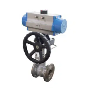
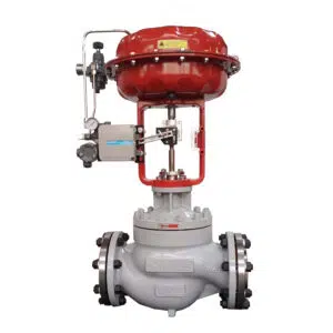
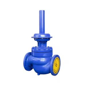
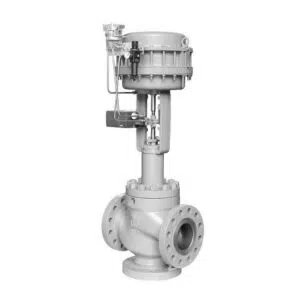
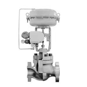
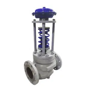
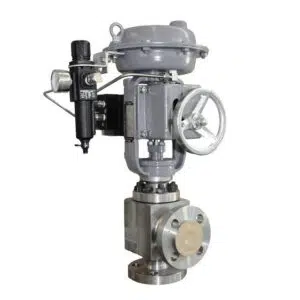
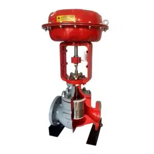
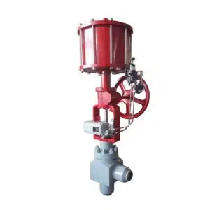
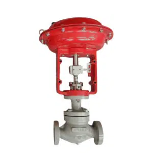
The control valve is the final control process in an automatic system. There are pneumatic, electric, hydraulic, and smart digital types of control valves. Utilized in process lines to control the flow of medium, and control valve process according to required settings. It has far-reaching meaning on safe and balanced production. There is an introduction of control valve installation, operation, and maintenance according to the actual production condition.
The principle and significance of installing control valve:
a. Safety
1. Valve leakage prevention: Valve leakage is not allowed in the process of production. During the operating time, it will cause valve leakage if packing and flange gasket part has even small gap or hole. If the operating conditions of liquid medium are very harsh (high temperature, high pressure, corrosive medium), the damage will be more and more serious, and the leakage will be more and more severe. Therefore, the selection of packing, sealing method, pressure reduction, using well-sealing valves are all factors considered by the installation personnel, and are also the basic conditions to prevent valve leakage.
2. Install vent or discharge valves. Any pipeline design and installation will accumulate high-pressure liquid when it is cut off. If the potential energy of the accumulated fluid is very dangerous, vent or discharge valves should be installed on each side of the control valve. Two vent or discharge valves should be installed on the valve with a large amount of high-pressure materials. A large amount of high-pressure fluid accumulated between the shut-off valves may accumulate considerable force, and serious personal accidents may occur if the operation of releasing the pressure of control valve is careless. After the system is cut off, the pressure can be maintained for a period of time. Keep valve opened will be a safe step to reduce pressure and release harmful fluid. And also choosing a rate limit vent valve can protect the operating stuff. If the fluid containing suspended particles, the vent will be blocked easily, therefore, at the top of pipeline should install bigger size vent valve for safely release.
3. Safe pipeline: Sand, scale, metal chips and other substances in the pipeline will damage the surface of the control valve and make it not close tightly. Therefore, before installing control valve all the pipeline and fittings should be purged and extremely purified. If the releasing fluid is harmful gas, the vent pipeline should connect to a safe place. Even it is non-flammable gas should release with vent to avoid blowing out the gas with rust or other substance and injury to the operator. If the discharged fluid is a dangerous liquid, connect the vent pipe to a safe container. During operation, the valve may be very hot, and precautions must be taken to prevent scalding the operator. When installing the pipe fittings connected by screws, it is necessary to prevent the sealant from falling into the installation pipeline. Generally, PTFE sealing belt should be used instead of sealant; The steam pipe near the upstream or downstream of the control valve shall be insulated. In the pipeline system with serious pressure fluctuation, pipeline buffer is required.
b. Utilize performance
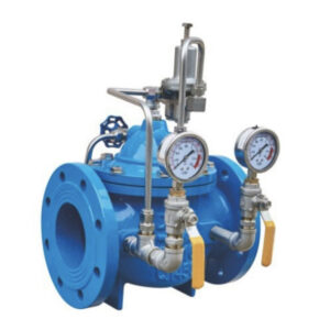
When installing control valve, its performance should not be affected by the dynamic as far as possible. The valve inlet is a straight pipe section, which can stabilize the pressure of the fluid entering the valve. The valve can ensure a stable flow at each opening. Generally, the experience length of the straight pipe section should be 10-20 times of the pipe diameter, and the straight pipe section of the outlet piping should also have enough length. Generally, it is 3-5 times of the pipe diameter. Of course, the longer the pipe section is, the better the performance is. The pressure gauge should be installed at the front and the back of the valve to show whether the pressure is stable. Under actual situation of checking the flow state and system fault, it is conducive to judging the operation characteristics and fault state of the valve, and is conducive to the operators to accurately observe the actual situation and adjust the operation parameters.
c. Good installation position, easy access, improve work efficiency, save maintenance costs
When installing the control valve, it is necessary to consider the on-site maintenance or routine disassembly and maintenance of the control valve. The maintenance cost depends on the convenience of approaching the valve. If it is necessary to disassemble the top bonnet with stem and plug, there should be enough space above the valve. If it is necessary to disassemble the bottom flange and stem, plug bonnets, there should be enough space. If the valve accessories such as handwheel, valve positioner and retaining valve need to be disassembled, the side of the valve should be enough space, and the bolts on the valve body flange should be disassembled with enough space. If the pipeline is vertical and the control valve must be installed horizontally, it is necessary to support the actuator on the pipeline with hook or brace, or support the control valve with v-bolt pipe clamp and support plate, eliminate the effect of thermal expansion.
d. Manual operation reduces incorrect operation
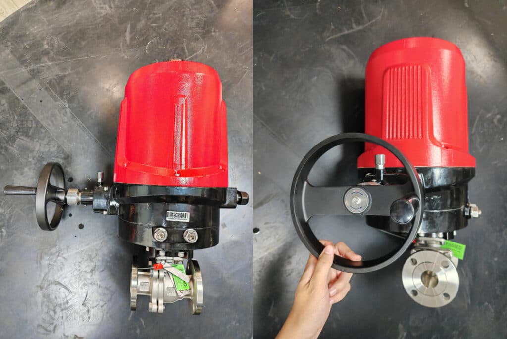
The installation position of the valve should be easy to operate. The operator should be able to see the display data of the indicator, the glass level gauge of the tank, and adjust the liquid level manually. He can see the pressure gauge or stem displacement scale of the pipeline. He can use the parameter indicator to make parameter changes. Installing the pipeline valve for manual operation should not affect the flow characteristics of the control valve. The control valve may or may not have a handwheel mechanism, so the bypass valve should be selected according to the situation.
e. Environment is the guarantee of production balance
The actuator of shall not be exposed to high temperature environment. When the temperature is higher than 38 ℃, the diaphragm, seal and positioner parts will be obviously affected by high temperature. In places with vibration, the vibration of the pipeline may cause the displacement of the pipeline. Therefore, the gas pipe, hydraulic pipe and electrical end should have enough flexibility, all the connecting lines should avoid water and liquid erosion, and the end of the pipe should be equipped with a connector to discharge the liquid. The simpler the disassembly and assembly, the better.
The valve positioner, valve position transmitter and limit switch shall be directly installed on the actuator, the quick discharge valve shall be installed on the vent lines of the actuator. The more transmission parts there are, the more likely they are to vibrate. When using electric control valve should pay more attention.
Common faults of control valve and their elimination
I. Main failure components of actuator
1.) Pneumatic and hydraulic actuator)Diaphragm: Under the normal condition of the air supply system, if the actuator can not act, it is the cause of diaphragm rupture and damage. When there are sharp corners, burr, and other defects on the metal contact surface, the diaphragm will be punctured. Another reason is that the diaphragm will be damaged due to material aging and long-time using.
2.) Piston, pneumatic and hydraulic actuator produces driving force. Due to damage there will be no driving force and will be insufficient due to wear.
3. ) The air pipe is the channel of input pressure actuator, if the connection is not firm or air leakage will make the input pressure actuator unable to work properly.
4.) Stem: bending, deformation, falling off, the connection between the push rod and the stem is not firm will cause insufficient travel or valve closed.
5.) Spring: spring fracture, spring elasticity loss will make the valve can not work properly.
2. Electric actuator
- ) Motor: check the motor can rotate or not, whether it is easy to overheat, whether there is enough torque and coupling force.
- ) Servo amplifier: check whether there is output or it can be adjusted.
- ) Reduction mechanism: check transmission parts — shaft, gear, and worm gear are damaged or overwearing.
- ) Moment of force controller: check for failure.
II. Main fault components of valve
1.Body: always check the corrosion and wear condition of the valve wall. Especially the valve used under corrosive medium and high pressure difference process conditions.
2. Plug: it is a movable closure element, which is easily damaged under high pressure difference and no-load condition due to the erosion, corrosion and particle collision of medium. Therefore, it is necessary to check the damage, abrasion andcorrosion frequently, repair and replace it in time.
3. Seat: the joint surface of valve seat is the key to ensure the valve to close. Due to the penetration of medium, the internal thread surface of fixed valve seat is often corroded and loosened. Special inspection shall be conducted during maintenance.
4. Stem: check the connection between valve stem, valve plug, and the stem is loose or not, and whether there is excessive deformation, crack, and corrosion.
5. Packing: check the tetrafluoroethylene or other packing is aged, deteriorated due to lack of oil, and whether the packing is compacted.
6. Gasket and O-ring, these vulnerable components are often cracked and aged.
